Advertisement
Quick Links
Tunable White two 0-10V Channel 96 watt LED Driver - Installation Instructions
Models PS010TW-96-24
Please read all instructions prior to installation and keep for future reference!
This LED Driver is to be installed in accordance with Article 450 of the National Electrical Code. The LED Driver must be
installed in a well ventilated area and free from explosive gases and vapors. Proper operation requires the free flow of air. As
this LED Driver is hardwired, it should only be installed by a qualified electrician. Suitable For Damp Location.
Input
120 - 277V AC, 1.1A, 50/60Hz
Output
24V DC, 4.0A
Max. wattage
96 W
1
Before installing, check the label and ensure the LED
Driver has the proper input voltage, output voltage, and
wattage for the job. Check the wire markings to ensure
they match the wiring diagram below. Refer to table
above for the maximum loads!
2" min.
1.1 LED Driver can be mounted vertically or horizontally. With a
minimum of 2" clearance around LED Driver to provide proper
air circulation.
3
3.1 Connect the 120-277V AC
power into the housing from
the electrical panel.
Followed by connecting the
24V DC low voltage
conduit, one for the LED &
other for the controller
wires. Refer to the diagram
below to make all the
proper wiring connections.
*LUMINII RESERVES THE RIGHTS TO CHANGE SPECIFICATION & INSTRUCTION WITHOUT NOTICE
2" min.
2" min.
Wiring diagram connecting
to LLDW36 LineLED
cool+
0-10V controller
yellow
control input 2
(color temp)
control input 1
(intensity)
Wiring diagram connecting
to LLDW52 LineLED
cool+
Vin2+
0-10V controller
yellow
red
gray-
control input 2
(color temp)
purple+
control input 1
gray-
(intensity)
purple+
2.6"
5.2"
2
2.1
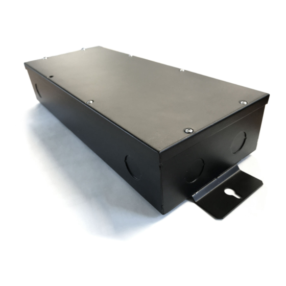
housing
2.1 Remove the eight Phillips screws from the top of the driver
housing and pull the cover off to expose the driver wires.
PS010TW-96-24 power supply
LED Driver 96W max
-
+
warm-
warm+
Vin2+
Vin2-
cool-
Vin1-
Vin1+
yellow
blue
black
red
red
black
blue
SLD-DIM-TW2
gray-
Tunable white LED PWM dimming module
purple+
Dimming range: 0-100%
0/1-10V control1, 0/1V=0% light output
10V=100% light output
gray-
0/1-10V control2, 0/1V= 100% warm
purple+
10V=100% cool
PWM Output to LED Modules (8-48V PWM, 1K Hz)
PS010TW-96-24 power supply
LED Driver 96W max
-
+
warm-
warm+
Vin2-
cool-
Vin1-
Vin1+
blue
yellow
black
blue
black
red
SLD-DIM-TW2
Tunable white LED PWM dimming module
Dimming range: 0-100%
0/1-10V control1, 0/1V=0% light output
10V=100% light output
0/1-10V control2, 0/1V= 100% warm
10V=100% cool
PWM Output to LED Modules (8-48V PWM, 1K Hz)
T 224.333.6033
PLENUM FOR
www.opticarts.com
SUCH USE IN
ACCORDANCE
WITH UL2043
Page 1 of 2
13.4"
14.4"
Phillips screw
cover
120 - 277V AC
L
N
GRD
LLDW36 Dynamic white
WW
-
+
-
CW
reference LineLED wire lead
24VDC
labels to determine polorarity
120 - 277V AC
L
N
GRD
LLDW52 Dynamic white
+ +
24VDC
REV0.0 11142019
Advertisement

Related Manuals for luminii Optic Arts PS010TW-96-24


Summary of Contents for luminii Optic Arts PS010TW-96-24
- Page 1 0/1-10V control1, 0/1V=0% light output 10V=100% light output control input 1 gray- 0/1-10V control2, 0/1V= 100% warm (intensity) purple+ 10V=100% cool PWM Output to LED Modules (8-48V PWM, 1K Hz) REV0.0 11142019 *LUMINII RESERVES THE RIGHTS TO CHANGE SPECIFICATION & INSTRUCTION WITHOUT NOTICE...
- Page 2 Page 2 of 2 screw 4.1 Insert the wire nut connections in the driver housing and close housing cover and secure using the 8 screws. cover driver housing REV0.0 11142019 *LUMINII RESERVES THE RIGHTS TO CHANGE SPECIFICATION & INSTRUCTION WITHOUT NOTICE...
Need help?
Do you have a question about the Optic Arts PS010TW-96-24 and is the answer not in the manual?
Questions and answers