Table of Contents
Advertisement
Quick Links
Advertisement
Table of Contents

Related Manuals for Servomex NanoTrace DF-745SG


Summary of Contents for Servomex NanoTrace DF-745SG
- Page 1 NanoTrace Moisture Analyzer DF-745SG OPERATOR MANUAL...
- Page 2 No part of this publication may be reproduced, stored in a retrieval system or transmitted in any form, or by any means including electronic, mechanical, photocopying, recording or otherwise without prior written permission of Servomex Corporation. NanoTrace Moisture Analyzer is a trademark of Servomex Corporation. VCR is a registered trademark of the Cajon Company.
- Page 3 Your NanoTrace Moisture Analyzer has been designed, manufactured and is supported under ISO-9001 controls, thus helping to insure the highest possible standards of quality. Every analyzer that Servomex manufactures is tested and operated on a variety of gas concentrations to insure that it functions properly when you receive it.
- Page 5 Follow the procedure below to unpack your NanoTrace Moisture Analyzer 1. Examine the condition of the packaging and its contents. If any damage is apparent, immediately notify the carrier and Servomex. Do not proceed with the installation. 2. Check the contents against the packing slip to make sure the shipment is complete.
- Page 6 Thank you for selecting the NanoTrace Moisture Analyzer. Servomex designs, manufactures, exhaustively tests, and supports every analyzer under the tightest quality controls. You should expect every Servomex analyzer to arrive in perfect working order and, with good maintenance, provide years of trouble-free service.
-
Page 7: Table Of Contents
1 Table of Contents Table of Contents ..............1 Table of Figures......................3 Cautions ................... 7 Symbols and Explanations ..................7 Important Warnings....................7 Specifications ................9 Moisture .........................9 General........................9 Installation, Start Up and Shut Down ........13 Analyzer Installation.....................13 4.1.1 Pneumatic Pressure Line Connection - Optional........13 4.1.2 Sample Gas Connections................14 4.1.3... - Page 8 7.4.10 Graph Setup ..................53 7.4.11 GSF Scaler Editor ................54 7.4.12 Diagnostics Menu ................55 7.4.13 Power Up Default – Optional..............60 7.4.14 Date/Time ....................61 7.4.15 Communications ..................62 7.4.16 Download System Data ................63 7.4.17 System Info ..................64 Sample Gas Preparation and Delivery ......... 67 Introduction ......................67 Flow Rate Effects on Sensor Performance .............67 Sample Gas Scale Factor..................67...
-
Page 9: Table Of Figures
1.1 Table of Figures Figure 1: Overall View ......................11 Figure 2: Major Internal Components..................13 Figure 3: Rear Gas Connections ....................14 Figure 4: Rear Gas Connections and Controls with Optional Gas Panel ........15 Figure 5: AC Power Connections....................16 Figure 6: AC Power Connections with Optional Gas Panel ............ - Page 10 Figure 51: Graph Setup Menu ....................53 Figure 52: Graph Setup Screen ....................54 Figure 53: Graph Setup Menu ....................54 Figure 54: GSF Warning ......................54 Figure 55: Gas Scaler Editor..................... 55 Figure 56: Diagnostics Menu....................55 Figure 57: Active Zero On/Off Menu..................56 Figure 58: Test Relays Menu ....................
- Page 11 Table of Tables Table 1: Pin-out of Serial Comm Connector J5 ................. 26 Table 2: Serial Communications Connections................26 Table 3: Pin-Out of Moisture Signal Output Connector J4 ............27 Table 4: Pin-Out of Relay Connectors J8 and J9 ............... 27 Table 5: Alarm Codes.......................
-
Page 13: Cautions
The analyzer must be operated in a manner specified in this manual. Servomex cannot be responsible for direct or consequential damages that result from installing or operating the analyzer in a manner not described in this manual. - Page 14 CAUTION Do not setup or operate this analyzer without a complete understanding of the instructions in this manual. Do not connect this Analyzer to a power source until all signal and plumbing connections are made. CAUTION This analyzer must be operated in a manner consistent with its intended use and as specified in this manual.
-
Page 15: Specifications
3 Specifications 3.1 Moisture Lowest Detection Level (LDL): 100 ppb @ Constant Conditions Resolution: Analytical (Smallest Detectable Change): 10 ppb Display: 0.1 ppb Accuracy: Greater of: 0-20 ppm range: ±5% of reading or ±25 ppb @ Constant Conditions 21-100 ppm range: ±10% of reading or ±100 ppb @ Constant Conditions Speed of Response: Typically less than 3 minutes to reach 90 percent of an upward step change Upset Recovery Time: Typically less than 5 minutes from a high ppb upset to... - Page 16 Sample Temperature: 10° C to 80°C (50° F to 176° F) EMI Sensitivity: Tested to standards EN61000-3-3 and EN61326-1 Audible/Visual Alarm Status Indicators: Four Moisture levels, Temperature, Moisture cell Diagnostic, Zero Verification or Calibration in Process, Moisture Analyzer off-line, Analog output freeze during calibration. Alarm Relays: Four non-latching, independently assignable to moisture alarms or to moisture calibration-in-process indicator.
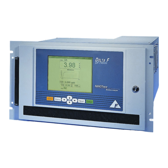
- Page 17 Figure 1: Overall View Specifications DF-745SG...
-
Page 19: Installation, Start Up And Shut Down
4 Installation, Start Up and Shut Down Installation of the analyzer requires the following steps be followed: Connecting the pneumatic pressure service to the pneumatic inlet fitting Connecting the sample gas line to the analyzer inlet fitting Making the power connection to the analyzer POWER SWITCH USB PORT H O SENSOR... -
Page 20: Sample Gas Connections
4.1.2 Sample Gas Connections 4.1.2.1 Sample Gas Inlet Connection Sample gas is connected to the analyzer via a ¼ inch male swivel VCR fitting labeled Process Inlet at the rear of the instrument as shown in Figure 3. Sample pressure of 30 – 150 psig is required and is regulated internally. Pre-purge the line by connecting to the analyzer (with a new VCR filter gasket) only finger tight and flowing gas for 15 minutes. -
Page 21: Electrical Connections
4.1.2.2 Sample Gas Outlet Connection The sample gas outlet connection is a ¼ inch compression fitting labeled Moisture Sensor Outlet as shown in Figure 3. If a connection must be made to the exhaust, it must provide minimal backpressure. NOTE: If the Hydrogen Service Safety System is included, the sample outlet line must be made of steel. - Page 22 installed, this option impacts the electrical wiring, gas plumbing and operation of the analyzer. See page 83 for additional installation and operation information. NOTE, if equipped with the Hydrogen Safety Service System, when shipped from the factory the analyzer will be configured through the GSF screen to measure hydrogen.
-
Page 23: Analyzer Start Up
Open the door and turn on the power using the main power switch inside the analyzer. See Figure 2. The analyzer will undergo a series of Diagnostic Procedures while the various startup screens are displayed. Next, the Servomex Corporation logo is briefly displayed and then the data display appears with the “Warming Up”... -
Page 24: Gas Pressure And Flow Settings
The connections at the rear of the gas delivery system include a ¼” VCR swivel connection for the process inlet, a ¼” compression outlet for the moisture cell, an optional pneumatic gas connection (1/8” compression), and an optional ¼” compression outlet for the bypass loop. Also on the rear of the gas delivery system, if equipped, are a sample gas regulator to adjust the internal sample pressure and a bypass flow meter. -
Page 25: Download System Data
cell is isolated, establish process flow via the Main menu. See page e. Use the regulator to adjust the flow through the cell to 1 slpm (2 scfh) as shown on the flowmeter behind the front door. NOTE: This flow rate may be reduced to minimize gas consumption but the flow rate will directly impact the overall system speed of response. - Page 26 NOTE: See the section on Power up Default on page 60 for setting user selectable preferences at the time of power up. Loss of power will result in automatic valve closure and the following restoration of power will result in the “Scan Disk” function occurring before system start-up. FLOW METER MOISTURE SENSOR OUTLET (FRONT)
- Page 27 FLOW METER MOISTURE SENSOR OUTLET (FRONT) REAR PANEL .010 ORIFICE REGULATOR ADJUSTMENT PROCESS INLET FLOWSWITCH BYPASS FLOWMETER (REAR) BYPASS FLOW ADJUST BYPASS OUTLET Figure 9: Block Diagram of Gas Flow Path with Optional Isolation Valves Installation, Start Up and Shut Down DF-745SG...
-
Page 29: Options
5 Options The following options to the DF-745SGSG are available at the time of order. 5.1 Key Lock An optional key lock can be installed in the door of the analyzer to prevent access to the power switch and other internal components. The lock is supplied with two keys. - Page 30 DF-745SG Options...
-
Page 31: Connecting To External Devices
6 Connecting to External Devices The analyzer can be interfaced to a variety of external devices via the ports on the rear panel. Alarm contacts, voltage, and current outputs, and serial communications are supported. All outputs, analog or digital, are fully isolated from earth ground. -
Page 32: Analog Signal Outputs - J4
See the chapter on Communications on page 62 for additional information on setting unit ID’s and baud rates. A program to facilitate serial communications is available from Servomex. Pin # Signal Description J5-8 Ground J5-7 4 wired 485 paired with TX+... -
Page 33: Relay Ports - J8, J9
J4 Pin # Moisture Signal Description J4-8 Ground J4-7 J4-6 A Out + Analog Voltage Output (+) J4-5 A Out - Analog Voltage Output (-) J4-4 Unused J4-3 Unused J4-2 4-20 mA + 4-20 mA Output (+) J4-1 4-20 mA - 4-20 mA Output (-) Table 3: Pin-Out of Moisture Signal Output Connector J4 6.4 Relay Ports –... - Page 34 The relays are wired for Fail Safe operation such that a Normally Open (No alarm) contact connects to common when an alarm occurs or when power to the instrument is lost. The relay wiring can be tested with the Relay test routine found on page 55. DF-745SG Connecting to External Devices...
-
Page 35: User Interface
7 User Interface 7.1 Data Display Screen The front panel display consists of the Graphical User Interface (GUI), as displayed on the view screen in Figure 11 below. Figure 11: Data Display Screen The various elements of the main data display screen are as follows: ... -
Page 36: Menu Structure
Menu Next Enter Figure 12: Keypad Once in the menu, the arrow keys ( ) highlight the various menu features. When the desired selection is highlighted, the right arrow will access the submenu if available (denoted by a right arrow next to the menu text). The ‘Next’ key and the ‘Enter’... -
Page 37: 745Sg Gsf
The Main Menu is accessed by pressing the Menu key on the front panel. Use the arrow keys ( ) to navigate up and down through the list. Select the highlighted item with the Enter key on the front panel. If a menu item is grayed out as shown in Figure 14, then the option is not installed, and as a result the item is not available. - Page 38 Defining a gas mixture for moisture analysis can be accomplished in two ways. The user can select gases from a table of thirteen supported gases, and then specify the % volume for each gas, or the user can select a pre-defined mixture called a template.
- Page 39 GSF log file as described on page 47. *There are 13 standard gases in the Supported Gases table. Up to 10 additional user-specified gases can be added to the table. Please contact Servomex Support for further information. 7.4.1.2 Template Display – Creating/Applying/Editing/Deleting a User...
- Page 40 Access to the template display screen is gained through the Support Gases display. To switch between the ‘Supported Gases’ display, Figure 16 and the ‘Template’ display, Figure 17, use the Up arrow key to move to the top of the supported gases list, at which point the arrow on the screen will turn red.
- Page 41 3. Accept the entry as a new template name. If the template name already exists, it overwrites without confirmation. If the template name has fewer than 3 characters, no new template is generated. 4. Limitation: The soft keyboard will only be displayed for the first time after activating the "GSF Editor".
-
Page 42: Isolate Analyzer - Optional
top of the supported gases list, at which point the arrow on the screen will turn red. Hit the Up arrow key one more time and the screens will toggle between Supported Gases and Template. Note that the red arrow key is displayed only when the top item is selected in the "Supported Gases"... -
Page 43: Restore Sample Gas Flow - Optional
Figure 20: Isolate Warning While the moisture cell is isolated from gas flow, a warning will appear at the bottom of the main display indicating “Isolated”. 7.4.3 Restore Sample Gas Flow – Optional Figure 21: Restore Sample Gas Flow This command allows the user to return the analyzer gas flow to normal after isolation. - Page 44 Figure 22: Calibrate Menu 7.4.4.1 Check/Adjust Zero Figure 23: Check/Adjust Zero Menu The Check/Adjust Zero screen displays many pieces of information including a live reading of moisture in ppb (or ppm) and the state of the zero gas control valves. Also depicted are Zero Reference and Zero Offset values.
- Page 45 A relay is available on the Analog Output Setup Screen (see page 53) to signal that a zero calibration is taking place, and the analog output signal can also be frozen or allowed to update during the calibration process. Figure 24: Check/Adjust Zero Screen 7.4.4.1.1 User Zero Offset Figure 25: User Zero Offset The User Zero Offset function enables the user to add a given moisture ppb value...
- Page 46 hit the Enter key which will move the highlighted area to the Apply button and hit Enter to set the value. Use the Next key to go back and change the value or move to the Done button, followed by hitting the Enter key to leave the screen. Using the ESC key at any time will exit the screen making no changes and return to the main display.
-
Page 47: Data History Routine
A relay is available on the Analog Output Setup Screen (see page 53) to signal that a zero calibration is taking place, and the analog output signal can also be frozen or allowed to update during the calibration process. 7.4.5 Data History Routine Figure 27: Data History Menu The Data History Screen (Figure 28) enables the user to see the data history displayed in strip chart form on the front display. -
Page 48: Data Downloader Routine
The data history may be downloaded to a USB memory stick, by using the Next key to move to the Download box and hitting ENTER. A screen will appear, requesting that a memory stick can be placed in the external USB socket. The socket is located behind the front door on the left side of the chassis. - Page 49 The Moisture Data Downloader screen, Figure 32, enables the user to label data with unique location names as well as to view and download specified data. The Next key is used to toggle through the various options on the screen and the arrow keys ( ...
- Page 50 The view location function is used to view data previously stored in the system sorted by location. On the Moisture Data Downloader screen Figure 32, use the Next key to move to the list of existing names and then use the arrow keys ( ...
-
Page 51: View Logs Menu
the action. If accepted, the name will be removed from the list of available locations. Figure 35: Delete Selection 7.4.7 View Logs Menu View Logs allows the user to easily access past events that may be connected with past operational changes (e.g., zero) or instrument upsets. Use the arrow keys ( ... - Page 52 The Moisture Zero Log reports on adjustments made to the moisture cell zero setting. The date and time of the zero calibration is noted. The zero is listed as either Manual or Automatic. Notes are also given as to if the zero was aborted, failed due to timeout, or in the event of an Automatic Zero, if it were scheduled.
- Page 53 141 = sample gas pressure outside of pressure matrix range. 191 = fan condition voltage out of range – “Fan Failure” Contact Servomex for assistance in interpreting the various codes if one should appear on the screen. Figure 40: System Error Code Screen 7.4.7.3 GSF Log...
-
Page 54: Analyzer Setup
Figure 42: GSF Log 7.4.8 Analyzer Setup Figure 43: Analyzer Setup Menu The analyzer setup menu allows the user access to the Alarm Setups, Analog Output setup and Graph setup. Use the arrow keys ( to scroll up and down through the list. Pressing ESC will return to the main display. -
Page 55: Table 5: Alarm Codes
Figure 44: Alarm Setup Menu Alarm Number Function Moisture Level 1 Moisture Level 2 Moisture Level 3 Moisture Level 4 Pressure Temperature System Table 5: Alarm Codes The temperature alarm indicates an out of specification ambient temperature condition in the analyzer cabinet. The pressure range alarm is related to the pressure in the gas path. - Page 56 repaired. A warning describing this condition will appear over the main display and the user will be unable to restore gas flow until the fan is repaired. See Fan Failure on page 59. 7.4.8.2 Moisture Alarm Setup The Setpoint value refers to the limit above or below which the alarm is triggered. The Trip command sets the above/below parameter.
- Page 57 The system is constantly monitoring the ambient temperature in the analyzer cabinet. If enabled on the Temperature Alarm Setup screen, an alarm can be assigned to trip if the ambient temperature exceeds preset limits. The user may assign the temperature alarm to one of four relays. Use the Next key to move from between fields and use the arrow keys ( ...
-
Page 58: Analog Output Setup
Use the Next key to move from between fields and use the arrow keys ( to change the highlighted selections and to enter numerical values. When done, use the Next key to move to the Accept button and hit the Enter key to return to the main display. -
Page 59: Graph Setup
range is required, rather than two, then the value of FS B should be set to equal the FS A value. Figure 50: Analog Output Setup Screen A window as narrow as 10% of the analyzer’s decades can be set for the full-scale analog output. -
Page 60: Gsf Scaler Editor
Figure 52: Graph Setup Screen 7.4.11 GSF Scaler Editor Figure 53: Graph Setup Menu The Gas Scaler Editor screen, as shown in Figure 55 enables the User to adjust the moisture reading by a factor of 0.3 to 3.0 for each gas included in the matrix. Use the Next key to move from between fields and use the arrow keys ( ... -
Page 61: Diagnostics Menu
Figure 55: Gas Scaler Editor 7.4.12 Diagnostics Menu The Diagnostics menu gives the user access to control the Active Zero function, to test the Relays and Analog Outputs, and to check the Signal Monitor. Use the arrow keys ( to scroll up and down through the list. Pressing ESC will return to the main display. - Page 62 O readings (display and output) to compensate for the long term downward trending in the readings during cleanup. The Active Zero Offset provides an automatic addition of offset that occurs in miniscule steps, and within set guidelines, corresponding to predictable behavior during cleanup. Figure 57: Active Zero On/Off Menu When Active Zero Offset is enabled through the Diagnostics Menu, the User Zero Offset feature is disabled and vice versa.
- Page 63 7.4.12.2 Test Relays Figure 58: Test Relays Menu The Test Relays screen, as shown in Figure 59, is used to assure that the relay outputs are functioning properly. When the Test Relays screen is selected, the NEXT key is used to move to the number field where the arrow keys ( ) are used to choose the appropriate relay number.
- Page 64 7.4.12.3 Test Analog Voltage Output Figure 60: Test Analog Outputs Menu The Test Output screen, as shown in Figure 61, is used to calibrate the analog recorder output. When the Test Output screen is selected, the NEXT key is used to move to the percentage field where the arrow keys ( ) are used to choose the appropriate setting.
- Page 65 7.4.12.4 Signal Monitor Figure 62: Signal Monitor Menu The Signal Monitor depicts 18 system parameters in numerical order. Each parameter is unique for each system. In the event of a system error, these parameters can be used as a diagnostic tool. See page 46 for additional information on system errors.
-
Page 66: Power Up Default - Optional
Figure 64: Fan Failure Alarm 7.4.13 Power Up Default – Optional Figure 65: Power Up Default Menu This menu item is only available on analyzers equipped with the isolation valve option. Figure 66: Power Up Default Screen DF-745SG User Interface... -
Page 67: Date/Time
The Power Up Default SubRoutine allows the user to determine the various default states during analyzer power up. The power up states are useful because they determine whether, for instance, the sensor is protected from ambient air contamination or whether it is configured the best way for rapid station to station transfer and measurement. -
Page 68: Communications
Figure 68: Date/Time Setup Screen 7.4.15 Communications Figure 69: Communications Menu Figure 70: Communications Setup Screen The Communications screen is used to set parameters related to serial PC communications. Accessed from the System menu, the Next key is used to moved DF-745SG User Interface... -
Page 69: Download System Data
USB memory stick, and the files can either be mailed or e-mailed to Servomex for evaluation. Install a memory stick into the external USB socket located behind the front door and on the left side of the analyzer. -
Page 70: System Info
All files are then automatically compressed and loaded as one file on the memory stick, which then can be used to forward the information to Servomex for evaluation. 7.4.17... - Page 71 Figure 76: System Info Screen 7.4.17.1 Firmware Upgrade While the Firmware Upgrade box is highlighted, hitting the Next key will bring up the Firmware Upgrade dialog box as in Figure 77 below. Figure 77: Software Upgrade Screen Place the USB memory stick in the external USB socket located behind the front door, When ready hit the Yes, Proceed key and follow the instructions.
-
Page 73: Sample Gas Preparation And Delivery
8 Sample Gas Preparation and Delivery 8.1 Introduction It is important to note key differences in each parameter to ensure a properly functioning system. Parameters such as flow, pressure, and background gas will have major effects on total system performance. 8.2 Flow Rate Effects on Sensor Performance Assuming a leak-free system, flow rate changes will have minimal effects on the performance of the moisture cell until the flow is so slow that the gas in the... -
Page 75: Service
In addition the failure will be logged in the System Error Log (see page 46). In the event of a system alarm contact Servomex with information as displayed in the log as well as on the Signal Monitor screen as shown on page 59. -
Page 76: Replaceable Parts List
5. Ensure that all internal components are adequately secured and put the analyzer in its original container. If the analyzer is being returned to the factory, call the nearest Servomex Business office to obtain a Return Material Authorization number. Clearly mark the Return Material Authorization number on the outside of the shipping container and on the packing list. -
Page 77: Theory Of Operation
10 Theory of Operation 10.1The Moisture Measurement 10.1.1 Moisture and the IR Spectrum Figure 78: Schematic of Moisture Cell The Nanotrace Moisture analyzer uses infrared (IR) absorption as its detection method. IR absorption is but a subset of the overall field of “spectroscopy,” which measures the interaction of light and matter. -
Page 78: Absorption Spectroscopy
10.1.2 Absorption Spectroscopy The relationship that defines absorption spectroscopy is known as Beer’s Law. Beer’s Law equates, in rigorous terms, the concentration of any absorbing molecule based on absorbed light intensity at a particular wavelength, given knowledge of the molecule’s absorption strength and the “path length” of the sample medium. -
Page 79: Safety
11 Safety 11.1General Warnings DANGER Potentially hazardous AC voltages are present within this instrument. Leave all servicing to qualified personnel. Disconnect the AC power source when installing or removing: external connections, the sensor, the electronics, or when charging or draining electrolyte. CAUTION Do not setup or operate the Analyzer without a complete understanding of the instructions in this manual. -
Page 81: Warranty
12 Warranty Servomex Corporation warrants each instrument manufactured by them to be free from defects in material and workmanship at the F.O.B. point specified in the order, its liability under this warranty being limited to repairing or replacing, at the Seller's option, items which are returned to it prepaid within one year from delivery to the carrier and found, to the Seller's satisfaction, to have been so defective. -
Page 83: Index
13 Index Serial Communications, 25 External Devices,Connecting to, 25 4-20mA Outputs, 27 Fan Failure, 59 Fan Failure Alarm, 59 Add Location, 44 Firmware Upgrade, 65 Alarm Setup, 49 Alarm Setup, Moisture, 50 Analog Output Setup, 52 Analog Signal Outputs, 26 Gas Flow and Pressure Regulation, 18 Analog Voltage Output, 23 Gas Scale Factor, GSF, 67... - Page 84 Shipping Return Material Authorization number, 70 Operating Voltage, 23 Set Location, 43 Options, 23 Signal Monitor, 59 Specifications, 9 System Error Codes, 46 System Info, 64 Power Up Default, 62 Pressure Alarm Setup, 51 Test Analog Voltage Output, 58 Test Relays, 57 Relay Ports, 27 Theory of Moisture Measurement, 71 Relays, Test, 57...
-
Page 85: Appendix A - User Menu Screens
14 Appendix A – User Menu Screens Page 31 Page 36 Page 37 Page 38 Page 41 Page 42 Page 45 Page 46 Appendix A – User Menu Screens DF-745SG... - Page 86 Page 47 Page 49 Page 52 Page 53 Page 55 Page 56 DF-745SG Appendix A – User Menu Screens...
- Page 87 Page 57 Page 58 Page 59 Page 60 Page 61 Page 62 Page 63 Page 64 Appendix A – User Menu Screens DF-745SG...
- Page 88 DF-745SG Appendix A – User Menu Screens...
-
Page 89: Appendix B - Hydrogen Service Safety System
15 Appendix B – Hydrogen Service Safety System The Hydrogen Service Safety System is designed to safeguard the DF-745SG from explosion hazards when operating on hydrogen sample gas under normal pressure and flow conditions as described in this manual. The instrument chassis and the remote pump, if equipped, are both protected by maintaining a safe condition within their respective enclosures. -
Page 90: Operation
mounted on the rear of the analyzer as well as to the 1/8 inch compression purge inlet fitting on the vacuum pump enclosure. 15.3Operation Before power is applied to the analyzer, the moisture cell is in an isolated state as the internal inlet and outlet valves are closed. In addition, the external sample interlock valve is closed and the case purge valve is open allowing customer supplied and regulated Nitrogen gas to purge the analyzer cabinet. - Page 91 CAUTION The Hydrogen Service Safety System is designed to be safe as provided by the factory when operating as described in the Operating Instruction Manual. DO NOT make additional penetrations in the enclosure. If there is a need to do so, please contact the factory.
- Page 92 Figure 79: Hydrogen Service Safety System DF-745SG Appendix B – Hydrogen Service Safety System...
- Page 94 Tel: +86 (0)21 6489 7570 Mumbai, India Tel: +91 22 39342700 www.hummingbirdsensing.com www.servomex.com Servomex has a policy of constant product improvement and reserves the right to change specifications without notice. © Servomex Group Limited. 2011. A Spectris company. All rights reserved.
Need help?
Do you have a question about the NanoTrace DF-745SG and is the answer not in the manual?
Questions and answers