Juniper SRX550 Hardware Manual
High memory services gateway
Hide thumbs
Also See for SRX550:
- Hardware manual (246 pages) ,
- Quick start manual (14 pages) ,
- Manual (10 pages)
Table of Contents
Advertisement
Quick Links
Advertisement
Table of Contents
Troubleshooting

Subscribe to Our Youtube Channel
Related Manuals for Juniper SRX550


Summary of Contents for Juniper SRX550
- Page 1 SRX550 High Memory Services Gateway Hardware Guide Published 2019-12-30...
- Page 2 END USER LICENSE AGREEMENT The Juniper Networks product that is the subject of this technical documentation consists of (or is intended for use with) Juniper Networks software. Use of such software is subject to the terms and conditions of the End User License Agreement (“EULA”) posted at https://support.juniper.net/support/eula/.
-
Page 3: Table Of Contents
SRX550 High Memory Services Gateway Power over Ethernet | 27 Accessing the SRX550 High Memory Services Gateway | 28 SRX550 High Memory Services Gateway Boot Devices and Dual-Root Partitioning Scheme | 29 Benefits of the SRX550 High Memory Services Gateway | 30... - Page 4 Interface Cabling and Wiring Specifications for the SRX550 High Memory Services Gateway | 68 RJ-45 Connector Pinouts for the SRX550 High Memory Services Gateway Ethernet Port | 69 RJ-45 Connector Pinouts for the SRX550 High Memory Services Gateway Console Port | 70...
- Page 5 Connecting to the SRX550 High Memory Services Gateway from the CLI with the USB Console Port | 95 Connecting the CLI at the User End for the SRX550 High Memory Services Gateway | 97 Configuring the Modem at the SRX550 High Memory Services Gateway End | 98...
- Page 6 Replacing a DC Power Supply on the SRX550 High Memory Services Gateway | 129 Removing a DC Power Supply Cable from the SRX550 High Memory Services Gateway | 130 Removing a DC Power Supply from the SRX550 High Memory Services Gateway | 130...
- Page 7 Services Gateway | 148 Troubleshooting the Power System on the SRX550 High Memory Services Gateway | 150 Using the RESET CONFIG Button on the SRX550 High Memory Services Gateway | 153 Changing the RESET CONFIG Button Behavior | 154 Contacting Customer Support and Returning the Chassis or Components...
- Page 8 viii Safety and Compliance Information Definitions of Safety Warning Levels | 167 General Safety Guidelines and Warnings | 170 Restricted Access Warning | 172 Qualified Personnel Warning | 175 Prevention of Electrostatic Discharge Damage | 175 Fire Safety Requirements | 177 Fire Suppression | 177 Fire Suppression Equipment | 177 Laser and LED Safety Guidelines and Warnings | 178...
- Page 9 DC Power Electrical Safety Guidelines and Warnings | 193 SRX550 High Memory Services Gateway Agency Approvals | 204 SRX550 High Memory Services Gateway Acoustic Noise Compliance Statements | 205 SRX550 High Memory Services Gateway Compliance Statements for EMC Requirements | 206...
-
Page 10: About The Documentation
Use this guide to install hardware and perform initial software configuration, routine maintenance, and troubleshooting for the SRX550 High Memory Services Gateway. After completing the installation and basic configuration procedures covered in this guide, refer to the Junos OS documentation for information about further software configuration. -
Page 11: Merging A Full Example
If the example configuration contains the top level of the hierarchy (or multiple hierarchies), the example is a full example. In this case, use the load merge command. If the example configuration does not start at the top level of the hierarchy, the example is a snippet. In this case, use the load merge relative command. -
Page 12: Merging A Snippet
xiii Merging a Snippet To merge a snippet, follow these steps: 1. From the HTML or PDF version of the manual, copy a configuration snippet into a text file, save the file with a name, and copy the file to a directory on your routing platform. For example, copy the following snippet to a file and name the file ex-script-snippet.conf. - Page 13 Table 1: Notice Icons Icon Meaning Description Informational note Indicates important features or instructions. Caution Indicates a situation that might result in loss of data or hardware damage. Warning Alerts you to the risk of personal injury or death. Laser warning Alerts you to the risk of personal injury from a laser.
- Page 14 Table 2: Text and Syntax Conventions (continued) Convention Description Examples Italic text like this Represents variables (options for Configure the machine’s domain which you substitute a value) in name: commands or configuration [edit] statements. root@# set system domain-name domain-name Text like this Represents names of configuration To configure a stub area, include statements, commands, files, and...
-
Page 15: Documentation Feedback
URL or page number, and software version (if applicable). Requesting Technical Support Technical product support is available through the Juniper Networks Technical Assistance Center (JTAC). If you are a customer with an active Juniper Care or Partner Support Services support contract, or are... -
Page 16: Self-Help Online Tools And Resources
JTAC hours of operation—The JTAC centers have resources available 24 hours a day, 7 days a week, 365 days a year. Self-Help Online Tools and Resources For quick and easy problem resolution, Juniper Networks has designed an online self-service portal called the Customer Support Center (CSC) that provides you with the following features: Find CSC offerings: https://www.juniper.net/customers/support/... - Page 17 C HAPTER Overview SRX550 High Memory (SRX550 HM) Services Gateway Overview | 21 SRX550 HM Chassis | 30 SRX550 HM Cooling System | 39 SRX550 HM Power System | 40 SRX550 HM Interface Modules | 46...
-
Page 19: Overview
The SRX550 High Memory Services Gateway has a modular 2U chassis that fits a 19-inch rack with a depth of approximately 18.1 inches. The SRX550 High Memory Services Gateway comes with 4 GB of DRAM memory and 8 GB of flash memory. -
Page 20: Srx550 High Memory Services Gateway Hardware Features
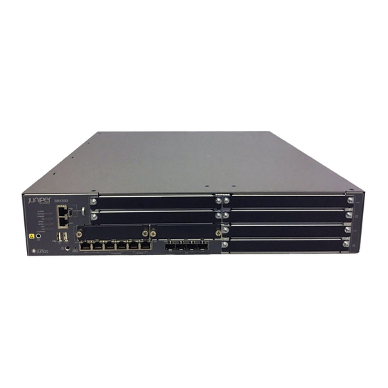
Figure 1: SRX550 High Memory Services Gateway SRX550 High Memory Services Gateway Hardware Features The SRX550 High Memory Services Gateway provides the following features: Symmetric Multiprocessing-based data forwarding. Hardware-based control and data plane separation. Six on-board 10/100/1000Base-T Gigabit Ethernet ports. - Page 21 Table 3: Software Features and Licenses Feature Category Feature Routing OSPF Routing Information Protocol version 1 (RIPv1) and version 2 (RIPv2) Static routes Intermediate System-to-Intermediate System (IS-IS) Connectionless Network Service (CLNS): End System-to-Intermediate System (ES-IS) protocol IS-IS extensions BGP extensions Static routes NOTE: CLNS is available only in packet-based mode.
- Page 22 Table 3: Software Features and Licenses (continued) Feature Category Feature Encapsulation Ethernet: Media access control (MAC) encapsulation 802.1p tagging Point-to-Point Protocol over Ethernet (PPPoE) Circuit cross-connect (CCC) Translational cross-connect (TCC) Synchronous Point-to-Point Protocol (PPP) Frame Relay High-Level Data Link Control (HDLC) 802.1Q filtering and forwarding Multilink Frame Relay (MLFR) Multilink PPP...
- Page 23 Table 3: Software Features and Licenses (continued) Feature Category Feature Security IPsec VPN for site-to-site or remote access encrypted tunneling Antivirus filtering, including full antivirus file-based scanning or Express-AV packet-based scanning Antispam and anti-phishing filtering Web filtering Content filtering based on file types and types of files within HTTP and HTTPS Unified threat management (UTM) Network attack detection Denial of service (DoS) and distributed denial of service (DDoS) protection...
- Page 24 Table 3: Software Features and Licenses (continued) Feature Category Feature System Junos XML protocol XML application programming interface (API) management The J-Web browser interface—For services gateway configuration and management Junos OS command-line interface (CLI)—For services gateway configuration and management through the console through Telnet, or SSH Simple Network Management Protocol version 1 (SNMPv1), SNMPv2, and SNMPv3 Network and Security Manager (NSM) J-Flow flow monitoring and accounting...
-
Page 25: Srx550 High Memory Services Gateway Power Over Ethernet
Voice over IP (VoIP) and IP phones and wireless access points. The PoE ports for the SRX550 High Memory Services Gateway reside on the individual XPIMs. The SRX550 High Memory Services Gateway supports the 16-Port Gigabit Ethernet XPIM with PoE. -
Page 26: Accessing The Srx550 High Memory Services Gateway
Class: Power allocation for interfaces is decided based on the class of powered device connected SEE ALSO SRX550 High Memory Services Gateway Gigabit-Backplane Physical Interface Modules | 46 SRX550 High Memory Services Gateway Power Supply | 40 Accessing the SRX550 High Memory Services Gateway The services gateway runs Junos OS. -
Page 27: Srx550 High Memory Services Gateway Boot Devices And Dual-Root Partitioning Scheme
SRX550 High Memory Services Gateway Boot Devices and Dual-Root Partitioning Scheme By default, the SRX550 High Memory Services Gateway boots from the following storage media (in order of priority): 1. Internal CompactFlash card (default; always present) 2. USB storage key (alternate) -
Page 28: Benefits Of The Srx550 High Memory Services Gateway
SRX550 High Memory Services Gateway Back Panel | 38 SRX550 High Memory Services Gateway Chassis The SRX550 High Memory Services Gateway chassis is a rigid sheet metal structure that houses all the other hardware components. Table 5 on page 31... -
Page 29: Srx550 High Memory Services Gateway Front Panel
Table 5: Physical Specifications for the SRX550 High Memory Services Gateway Physical Specification Value Chassis height 3.5 in. (8.8 cm) Chassis width 17.5 in. (44.4 cm) Chassis depth 18.2 in. (46.2 cm) Chassis weight (includes one power supply without any GPIMs or 21.96 lb. - Page 30 Table 6 on page 32 provides information about the front panel components of the services gateway with reference to Figure 2 on page Table 6: SRX550 High Memory Services Gateway Front Panel Components Number Component Location Description Front panel LEDs Left side of the Indicate the current status of the services gateway.
- Page 31 Table 6: SRX550 High Memory Services Gateway Front Panel Components (continued) Number Component Location Description Mounting brackets Sides of chassis Rack-mounting brackets attached when the services gateway is mounted on a rack. The mounting brackets are used to attach the services gateway to a rack or cabinet.
- Page 32 ESD grounding strap to prevent your panel body from sending static charges to the services gateway, which will damage the device. Figure 3 on page 35 shows how the slots on the front panel of the SRX550 High Memory Services Gateway are numbered.
-
Page 33: Srx550 High Memory Services Gateway Front Panel Leds
Figure 3: SRX550 High Memory Services Gateway Slot Numbers SRX550 High Memory Services Gateway Front Panel LEDs Figure 4 on page 35 shows the locations of the SRX550 High Memory Services Gateway front panel LEDs. Table 7 on page 36 describes the LEDs. - Page 34 Table 7: SRX550 High Memory Services Gateway Front Panel LEDs Label LED State Color Description ALARM On Steadily Amber Indicates a major alarm, such as low Services Processing Unit (SPU) memory (less than 10% remaining), session full, maximum number of VPN tunnels reached, high availability (HA) status changed, or redundant group member not found.
- Page 35 Table 7: SRX550 High Memory Services Gateway Front Panel LEDs (continued) Label LED State Color Description Steadily on Green All configured high availability links are available. High availability links are not working as expected and a cluster member might be missing or unreachable.
-
Page 36: Srx550 High Memory Services Gateway Back Panel
SRX550 High Memory Services Gateway. Figure 5: SRX550 High Memory Services Gateway Back Panel Table 8 on page 38 describes the components on the back panel of the SRX550 High Memory Services Gateway with reference to Figure 5 on page... -
Page 37: Srx550 Hm Cooling System
SRX550 HM Installation Overview | 75 SRX550 HM Cooling System The SRX550 High Memory Services Gateway cooling system consists of four fixed fans. The fans provide cooling to the components installed in the services gateway. To function properly, the entire cooling system requires an unobstructed airflow and proper clearance around the site. -
Page 38: Srx550 Hm Power System
SRX550 High Memory Services Gateway DC Power Supply Electrical Specifications | 45 SRX550 High Memory Services Gateway Power Supply The SRX550 High Memory Services Gateway uses either one AC or one DC power supply unit (PSU). The services gateway is equipped with one AC power supply (see... - Page 39 Figure 6: AC Power Supply Figure 7: DC Power Supply The power supplies provide different output wattage to the services gateway components according to the voltage requirements of the components. The power supply components are listed in Table 9 on page...
- Page 40 Table 9: Component Power Output/Consumption Power Supply Output/Consumption 645 W AC power supply This power supply can provide: 390 W at 12 V 255 W PoE on a single power supply, or with redundancy using the two power supplies 510 W PoE using the two power supply option operating as nonredundant NOTE: Using the two power supply option operating as nonredundant...
-
Page 41: Srx550 High Memory Services Gateway Supported Ac Power Cords
Feed B RTN connection for Feed B -48VDC connection for Feed B SRX550 High Memory Services Gateway Supported AC Power Cords WARNING: The AC power cord for the services gateway is intended for use with the services gateway only and not for any other use. -
Page 42: Srx550 High Memory Services Gateway Ac Power Supply Electrical Specifications
SRX550 High Memory Services Gateway AC Power Supply Electrical Specifications The AC power supply electrical specifications for the SRX550 High Memory Services Gateway are listed Table 12 on page Table 12: AC Power Supply Electrical Specifications for the SRX550 High Memory Services Gateway... -
Page 43: Srx550 High Memory Services Gateway Dc Power Cable Specifications
8 AWG, minimum 60°C wire, or as permitted by the local code SRX550 High Memory Services Gateway DC Power Supply Electrical Specifications Table 14 on page 46 lists the DC power supply electrical specifications for the SRX550 High Memory Services Gateway. -
Page 44: Srx550 Hm Interface Modules
Table 14: DC Power Supply Electrical Specifications for the SRX550 High Memory Services Gateway Power Requirement Specification DC input voltage Operating range: –40 to –72 VDC DC system current rating 16 A at –48 VDC RELATED DOCUMENTATION Clearance Requirements for Airflow and Hardware Maintenance of the SRX550 High Memory Services... - Page 45 20-gigabit GPIM slot 6, which refers to the top four slots 5 through 8. Figure 9 on page 47 shows how the slots on the front panel of the SRX550 Services Gateway are numbered. Figure 9: SRX550 Services Gateway Slot Numbers...
-
Page 46: Srx550 High Memory Services Gateway Mini-Physical Interface Modules
Remove the GPIM adapter before you install double-high, double-wide XPIM. SRX550 High Memory Services Gateway Mini-Physical Interface Modules The SRX550 High Memory Services Gateway has two slots (slots 1 and 2) for installing Mini-Physical Interface Modules (Mini-PIMs). A Mini-PIM is a network interface card that is installed in the services gateway to provide physical connections to a LAN or WAN. - Page 47 LTE Mini-Physical Interface Module (SRX-MP-LTE-AE and SRX-MP-LTE-AA) Wi-Fi Mini-Physical Interface Module (SRX-MP-WLAN-US, SRX-MP-WLAN-IL, and SRX-MP-WLAN-WW) For more information on the Mini-PIMs, see the SRX300 Series and SRX550 High Memory Gateway Interface Modules Reference. RELATED DOCUMENTATION SRX550 High Memory Services Gateway Front Panel | 31...
-
Page 48: Site Planning, Preparation, And Specifications
C HAPTER Site Planning, Preparation, and Specifications Site Preparation Checklist for the SRX550 HM Services Gateway | 53 SRX550 HM Site Guidelines and Requirements | 55 SRX550 HM Cable Specifications and Pinouts | 68 SRX550 HM Network Cable and Transceiver Planning | 71... -
Page 50: Site Preparation Checklist For The Srx550 Hm Services Gateway
Table 15 on page 53 summarizes the tasks you need to perform when preparing a site for installing the SRX550 High Memory Services Gateway. Table 15: Site Preparation Checklist for SRX550 High Memory Services Gateway Installation Performed Item or Task... - Page 51 Table 15: Site Preparation Checklist for SRX550 High Memory Services Gateway Installation (continued) Performed Item or Task Additional Information Date Notes Plan rack location, “SRX550 High Memory Services Gateway including required space Spacing of Mounting Bracket and Flange clearances. Holes” on page 67 Secure the rack to the “SRX550 High Memory Services Gateway...
-
Page 52: Srx550 Hm Site Guidelines And Requirements
General Site Installation Guidelines for the SRX550 High Memory Services Gateway The following precautions help you plan an acceptable operating environment for your SRX550 High Memory Services Gateway and avoid environmentally caused equipment failures: For the cooling system to function properly, the airflow around the chassis must be unrestricted. Allow sufficient clearance between the front and back of the chassis and adjacent equipment. -
Page 53: Srx550 High Memory Services Gateway Environmental Specifications
SRX550 High Memory Services Gateway Environmental Specifications Table 16 on page 56 provides the required environmental conditions for normal SRX550 High Memory Services Gateway operations. In addition, the site must be as dust-free as possible because dust can clog air intake vents, reducing the efficiency of the cooling system. -
Page 54: Srx550 High Memory Services Gateway Electrical Wiring Guidelines
SRX550 High Memory Services Gateway at your site. CAUTION: It is particularly important to provide a properly grounded and shielded environment and to use electrical surge-suppression devices. Table 17: Site Electrical Wiring Guidelines for the SRX550 High Memory Services Gateway Site Wiring Factor Guideline Signaling limitations To ensure that signaling functions optimally: Install wires correctly. -
Page 55: Srx550 High Memory Services Gateway Grounding Specifications
Table 17: Site Electrical Wiring Guidelines for the SRX550 High Memory Services Gateway (continued) Site Wiring Factor Guideline Electromagnetic Provide a properly grounded and shielded environment and use electrical compatibility (EMC) surge-suppression devices. Strong sources of electromagnetic interference (EMI) can cause the following damage: Destroy the signal drivers and receivers in the device. -
Page 56: Srx550 High Memory Services Gateway Physical Specifications
SEE ALSO Connecting the SRX550 HM Grounding Cable | 83 Connecting the SRX550 High Memory Services Gateway to a DC Power Source | 90 Powering On the SRX550 High Memory Services Gateway | 93 Powering Off the SRX550 High Memory Services Gateway | 93... -
Page 57: Clearance Requirements For Airflow And Hardware Maintenance Of The Srx550 High Memory Services Gateway
Clearance Requirements for Airflow and Hardware Maintenance of the SRX550 High Memory Services Gateway When planning the installation site for the SRX550 High Memory Services Gateway, you need to allow sufficient clearance around the rack. When planning the installation site for the services gateway, consider the following: For the cooling system to function properly, the airflow around the chassis must be unrestricted. -
Page 58: Rack Requirements For The Srx550 High Memory Services Gateway
Rack-Mounting Requirements and Warnings | 61 SRX550 High Memory Services Gateway Rack Size and Strength Requirements | 66 SRX550 High Memory Services Gateway Spacing of Mounting Bracket and Flange Holes | 67 Rack-Mounting Requirements and Warnings Ensure that the equipment rack into which the services gateway is installed is evenly and securely supported... - Page 60 De onderstaande richtlijnen worden verstrekt om uw veiligheid te verzekeren: De Juniper Networks services gateway moet in een stellage worden geïnstalleerd die aan een bouwsel is verankerd. Dit toestel dient onderaan in het rek gemonteerd te worden als het toestel het enige in het rek is.
- Page 61 Les directives ci-dessous sont destinées à assurer la protection du personnel: Le rack sur lequel est monté le Juniper Networks services gateway doit être fixé à la structure du bâtiment. Si cette unité constitue la seule unité montée en casier, elle doit être placée dans le bas.
- Page 62 Il Juniper Networks services gateway deve essere installato in un telaio, il quale deve essere fissato alla struttura dell'edificio. Questa unità deve venire montata sul fondo del supporto, se si tratta dell'unica unità da montare nel supporto. Quando questa unità viene montata in un supporto parzialmente pieno, caricare il supporto dal basso all'alto, con il componente più...
-
Page 63: Srx550 High Memory Services Gateway Rack Size And Strength Requirements
SRX550 High Memory Services Gateway Rack Size and Strength Requirements When installing the SRX550 High Memory Services Gateway in a rack, you must ensure that the rack complies with a 2U (19 in. or 45.6 cm) rack as defined in Cabinets, Racks, Panels, and Associated Equipment (document number EIA-310-D) published by the Electronic Industries Alliance (http://www.ecaus.org/eia/site/index.html). -
Page 64: Srx550 High Memory Services Gateway Spacing Of Mounting Bracket And Flange Holes
SRX550 High Memory Services Gateway Cabinet Size and Clearance Requirements You can install the SRX550 High Memory Services Gateway in a 19 in. (48.3 cm) cabinet as defined in Cabinets, Racks, Panels, and Associated Equipment (document number EIA-310-D) published by the Electronic Industries Alliance (http://www.ecaus.org/eia/site/index.html). -
Page 65: Srx550 High Memory Services Gateway Cabinet Airflow Requirements
SRX550 High Memory Services Gateway Cabinet Airflow Requirements When you mount the SRX550 High Memory Services Gateway in a cabinet, you must ensure that ventilation through the cabinet is sufficient to prevent overheating. Consider the following when planning for chassis... -
Page 66: Connector Pinouts For The Srx550 High Memory Services Gateway Ethernet Port
100Base-T operation NOTE: The Auxiliary port is not supported on the SRX550 Services Gateway. RJ-45 Connector Pinouts for the SRX550 High Memory Services Gateway Ethernet Port The port on the front panel labeled ETHERNET is an autosensing 10/100-Mbps Ethernet RJ-45 receptacle that accepts an Ethernet cable for connecting the services gateway to a management LAN (or other device that supports out-of-band management). -
Page 67: Connector Pinouts For The Srx550 High Memory Services Gateway Console Port
Signal Termination network Termination network RJ-45 Connector Pinouts for the SRX550 High Memory Services Gateway Console Port The port on the front panel labeled CONSOLE is an autosensing 10/100-Mbps Ethernet RJ-45 receptacle that accepts an RJ-45 cable for connecting the services gateway to a management LAN (or other device that supports out-of-band management). -
Page 68: Srx550 Hm Network Cable And Transceiver Planning
The Hardware Compatibility Tool enables you to search by product, displaying all the transceivers supported on that device, or category, by interface speed or type. The list of supported transceivers for the SRX550 HM is located at https://apps.juniper.net/hct/product/#prd=SRX550%20HM. -
Page 69: Initial Installation And Configuration
SRX550 HM Installation Overview | 75 Unpacking and Mounting the SRX550 HM | 76 Connecting the SRX550 HM to Power | 82 Connecting the SRX550 HM to External Devices | 94 Configuring Junos OS on the SRX550 HM | 100... -
Page 71: Srx550 Hm Installation Overview
SRX550 High Memory Services Gateway Installation Overview After you have prepared the site for installation and unpacked the SRX550 High Memory Services Gateway, you are ready to install the device. It is important to proceed through the installation process in the following order: 1. -
Page 72: Unpacking And Mounting The Srx550 Hm
IN THIS SECTION Unpacking the SRX550 High Memory Services Gateway | 77 Verifying Parts Received with the SRX550 High Memory Services Gateway | 78 Preparing the SRX550 High Memory Services Gateway for Rack-Mount Installation | 79 Installing the SRX550 High Memory Services Gateway in a Rack | 80... -
Page 73: Unpacking The Srx550 High Memory Services Gateway
Blank panels to cover any slots not occupied by a component The SRX550 High Memory Services Gateway is shipped in a cardboard carton and secured with foam packing material. The carton also contains an accessory box and quick start instructions. -
Page 74: Verifying Parts Received With The Srx550 High Memory Services Gateway
If any part on the packing list is missing, contact your customer service representative or contact Juniper customer care from within the U.S. or Canada by telephone at 1-888-314-5822. For international-dial or direct-dial options in countries without toll-free numbers, see https://www.juniper.net/support/requesting-support.html. -
Page 75: Preparing The Srx550 High Memory Services Gateway For Rack-Mount Installation
Verify that the site meets the requirements described in “Site Preparation Checklist for the SRX550 High Memory Services Gateway” on page Verify that you have the following parts available in your rack-mounting kit for the SRX550 High Memory Services Gateway: Rack-mounting brackets... -
Page 76: Installing The Srx550 High Memory Services Gateway In A Rack
SRX550 High Memory Services Gateway” on page Installing the SRX550 High Memory Services Gateway in a Rack You can front-mount the SRX550 High Memory Services Gateway in a rack. Many types of racks are acceptable, including four-post (telco) racks, enclosed cabinets, and open-frame racks. - Page 77 Figure 15: Installing the Rack Mount Brackets (Center Mount Position) 3. Have one person grasp the sides of the services gateway, lift it, and position it in the rack. 4. Align the bottom hole in each mounting bracket with a hole in each rack rail, making sure the chassis is level.
-
Page 78: Connecting The Srx550 Hm To Power
IN THIS SECTION Connecting the SRX550 HM Grounding Cable | 83 Installing an AC Power Supply on the SRX550 High Memory Services Gateway | 84 Connecting the SRX550 High Memory Services Gateway to the AC Power Source | 85 Installing a DC Power Supply on the SRX550 High Memory Services Gateway | 87... -
Page 79: Connecting The Srx550 Hm Grounding Cable
Connecting the SRX550 HM Grounding Cable You ground the services gateway by connecting a grounding cable to earth ground and then attaching it to the chassis grounding points located on the right side of the device (if you are facing the front of the chassis). -
Page 80: Installing An Ac Power Supply On The Srx550 High Memory Services Gateway
Follow the ESD and connection instructions for your site. If the power supply is correctly installed and functioning normally, the POWER LED lights steadily. Figure 17: Installing an AC Power Supply on the SRX550 High Memory Services Gateway... -
Page 81: Connecting The Srx550 High Memory Services Gateway To The Ac Power Source
A 645 W AC power supply with PoE support ships with the SRX550 High Memory Services Gateway. You connect AC power to the services gateway by attaching the power cord from the AC power source to the AC appliance inlet located on the power supply. - Page 82 Figure 18: Connecting an AC Power Cord 5. Dress the power cord appropriately. Verify that the power cord does not block the air exhaust and access to services gateway components or drape where people could trip on it. NOTE: The services gateway must be connected to earth ground during normal operation. The protective earthing terminal on the side of the chassis is provided to connect the services gateway to ground.
-
Page 83: Installing A Dc Power Supply On The Srx550 High Memory Services Gateway
3. Orient the power supply so that the locking lever is on the left. Figure 19: Installing a DC Power Supply on an SRX550 High Memory Services Gateway 4. Using both hands, slide the power supply straight into the chassis until the power supply is fully seated in the chassis slot. - Page 84 7. Verify that the DC power cables are correctly labeled before making connections to the power supply. In a typical power distribution scheme where the return is connected to chassis ground at the battery plant, you can use a multimeter to verify the resistance of the –48V and RTN DC cables to chassis ground: The cable with very large resistance (indicating an open circuit) to chassis ground will be –48V.
- Page 85 Figure 20: Connecting DC Power Cables 9. Replace the clear plastic cover over the terminal studs on the faceplate. 10. Verify that the power cables are connected correctly, that they are not touching or blocking access to services gateway components, and that they do not drape where people could trip on them. 11.
-
Page 86: Connecting The Srx550 High Memory Services Gateway To A Dc Power Source
Do not mix AC and DC power supplies within the same services gateway. Damage to the device might occur. A 645 W DC power supply with PoE support is available for the SRX550 Services Gateway. WARNING: Before performing the following procedure, ensure that power is removed from the DC circuit. - Page 87 NOTE: The DC cable should be of minimum 14 AWG. CAUTION: You must ensure that power connections maintain the proper polarity. The power source cables might be labeled (+) and (–) to indicate their polarity. There is no standard color coding for DC power cables. The color coding used by the external DC power source at your site determines the color coding for the leads on the power cables that attach to the terminals on the power supply.
- Page 88 Figure 21: Connecting DC Power Cables 6. (Optional) If you have two DC power sources and wish to deploy A/B feed redundancy for the services gateway, connect the DC power cables to B+ and B- terminals also. 7. Replace the clear plastic cover over the terminal studs on the faceplate. 8.
-
Page 89: Powering On The Srx550 High Memory Services Gateway
10 seconds. The services gateway immediately shuts down. NOTE: Graceful shutdown is not supported on the SRX550 High Memory Services Gateway. To remove power completely from the services gateway, unplug the AC power cord or DC power supply... -
Page 90: Connecting The Srx550 Hm To External Devices
Connecting the Modem to the Console Port on the SRX550 High Memory Services Gateway | 94 Connecting to the SRX550 High Memory Services Gateway from the CLI with the USB Console Port | 95 Connecting the CLI at the User End for the SRX550 High Memory Services Gateway | 97... -
Page 91: Connecting To The Srx550 High Memory Services Gateway From The Cli With The Usb Console Port
9. Power on the services gateway by pressing the Power button on the front of the services gateway. Verify that the POWER LED on the front panel turns green. Connecting to the SRX550 High Memory Services Gateway from the CLI with the USB Console Port... - Page 92 Figure 23: Connecting to the USB Console Port on the SRX550 Services Gateway To connect to the CLI using a local management device through the USB console port on the services gateway: 1. If you have not already done so, install the USB console driver software. Download a USB driver to the...
-
Page 93: Connecting The Cli At The User End For The Srx550 High Memory Services Gateway
Connecting the CLI at the User End for the SRX550 High Memory Services Gateway To connect to the CLI through a dial-up modem connected to the console port on the SRX550 High Memory Services Gateway: 1. Connect a modem at your remote location to a management device. -
Page 94: Configuring The Modem At The Srx550 High Memory Services Gateway End
Configuring the Modem at the SRX550 High Memory Services Gateway Before you can connect a dial-up modem to the console port on the SRX550 High Memory Services Gateway, you must configure the modem to accept a call on the first ring and to accept DTR signals. You... - Page 95 NOTE: These instructions use Hayes-compatible modem commands to configure the modem. If your modem is not Hayes-compatible, refer to the documentation for your modem and enter equivalent modem commands. To configure the modem on the services gateway end: 1. Connect the modem to the management device (a desktop or laptop computer). 2.
-
Page 96: Configuring Junos Os On The Srx550 Hm
Configuring Mini-Physical Interface Modules | 116 SRX550 High Memory Services Gateway Basic Connectivity Overview The Juniper Networks Junos operating system (Junos OS) is preinstalled on the SRX550 High Memory Services Gateway. When the services gateway is powered on, it is ready to be configured. -
Page 97: Built-In Ethernet Ports For The Srx550 High Memory Services Gateway
An adapter appropriate for your modem; for example, DB-25 male or similar Built-In Ethernet Ports for the SRX550 High Memory Services Gateway Before initial configuration, when the factory default configuration is active, the services gateway attempts to perform autoinstallation by obtaining a device configuration through all its connected interfaces, including the interface ge-0/0/0. - Page 98 Table 30: Default Interface Configuration for the Services Gateway Security DHCP Port Label Interface Connector Zone State Address ge-0/0/0 RJ-45 Untrust Client Dynamically assigned NOTE: If chassis clustering is enabled, use this port as the management port (fxp0). ge-0/0/1 (if RJ-45 Trust Server...
- Page 99 Table 30: Default Interface Configuration for the Services Gateway (continued) Security DHCP Port Label Interface Connector Zone State Address ge-0/0/4 RJ-45 Trust Server 192.168.4.1/24 ge-0/0/5 RJ-45 Trust Server 192.168.5.1/24 ge-0/0/6 No default Configuration ge-0/0/7 ge-0/0/8 ge-0/0/9 NOTE: If chassis clustering is enabled, we recommend using the port labeled 0/0 port as the management port (fxp0) and using the 0/1 port (if used) as the control port (fxp1).
-
Page 100: Viewing Factory-Default Settings Of The Srx550 High Memory Services Gateway
Management Access for the SRX550 High Memory Services Gateway Telnet allows you to connect to the SRX550 High Memory Services Gateway and access the CLI to execute commands from a remote system. Telnet connections are not encrypted and therefore can be intercepted. -
Page 101: Srx550 High Memory Services Gateway Secure Web Access Overview
Junos OS Public Sector Certifications. SRX550 High Memory Services Gateway Secure Web Access Overview You can manage a services gateway remotely through the J-Web interface. To communicate with the services gateway, the J-Web interface uses Hypertext Transfer Protocol (HTTP). HTTP allows easy Web access but does not include encryption. -
Page 102: Configuring Zero-Touch Provisioning On Srx Series Devices
Network Service Controller is a component of the Juniper Networks Contrail Service Orchestration platform that simplifies and automates the design and implementation of custom network services that use an open framework. For more information, refer to the Network Service Controller section in the datasheet at https://www.juniper.net/assets/us/en/local/pdf/... -
Page 103: Configuring The Srx550 High Memory Services Gateway Using J-Web
Configuring the SRX550 High Memory Services Gateway Using J-Web IN THIS SECTION Configuring Root Authentication | 107 Connect the Management Device to the Ethernet Port | 108 Verify the Settings | 109 Configuring Root Authentication To configure root authentication: 1. Connect the management device to the console port. See “Connecting to the SRX550 High Memory... -
Page 104: Connect The Management Device To The Ethernet Port
Connect the Management Device to the Ethernet Port To connect the management device to the Ethernet port on the SRX550 High Memory Services Gateway: 1. Connect any of the network ports numbered 0/1 through 0/5 to the Ethernet port on the management device, using an RJ-45 cable. -
Page 105: Verify The Settings
If the page does not load, perform the following checks to see if you can identify the problem: Check if the cable connecting the ISP-supplied device to the SRX Series device is firmly seated. Use the CLI ping command to verify that the SRX550 High Memory Services Gateway can be accessed from the management device. - Page 106 Figure 25: Connecting to the Console Port on the SRX550 High Memory Services Gateway NOTE: Figure 25 on page 110 shows a connection to a local management device. A remote connection to the services gateway through a modem requires the cable and connector shown (RJ-45 to a DB-9 serial port adapter), along with an adapter for your modem, which you must purchase separately.
-
Page 107: Connecting To The Srx550 High Memory Services Gateway From The Cli Remotely
Connecting to the SRX550 High Memory Services Gateway from the CLI Remotely You can connect an SRX550 High Memory Services Gateway to the CLI from a remote location through two dial-up modems: A modem that is connected to the console port on the services gateway... -
Page 108: Configuring The Srx550 High Memory Services Gateway Using The Cli
Configuring the SRX550 High Memory Services Gateway Using the CLI This procedure connects the device to the network but does not enable it to forward traffic. For complete information about enabling the device to forward traffic, including examples, see the appropriate Junos OS configuration guides. - Page 109 root# commit 8. Log in as the administrative user you configured in Step 6. 9. Configure the name of the device. If the name includes spaces, enclose the name in quotation marks (“ ”). configure [edit] admin# set system host-name host-name 10.
- Page 110 [edit] admin# set security nat source rule-set interface-nat from zone trust admin# set security nat source rule-set interface-nat to zone untrust admin# set security nat source rule-set interface-nat rule rule1 match source-address 0.0.0.0/0 destination-address 0.0.0.0/0 admin# set security nat source rule-set interface-nat rule rule1 then source-nat interface 15.
-
Page 111: Configuring Gigabit-Backplane Physical Interface Modules
Configuring Gigabit-Backplane Physical Interface Modules To configure Gigabit-Backplane Physical Interface Modules (GPIMs) on the SRX550 High Memory Services Gateway: 1. Verify that the GPIM is installed in the services gateway: user@host >show chassis hardware The following is a sample output of the command. -
Page 112: Configuring Mini-Physical Interface Modules
user@host> show chassis fpc pic-status 3. Verify that the network interface that you want to configure on the XPIM is up: user@host> show interfaces terse 4. Assign the interface an IP address: [edit] user@host# set interfaces interface-name unit 0 family inet address interface address/destination prefix 5. -
Page 113: Using The J-Web Interface
To enable the Mini-Physical Interface Module (Mini-PIM) installed on the services gateway, you must configure the basic settings for the Mini-PIM. You can perform the configuration tasks for this using either the J-Web interface or the CLI. Using the J-Web Interface To perform basic configuration for the Mini-PIM and to configure network interfaces for the services gateway using the J-Web interface: 1. -
Page 114: Using The Cli
Using the CLI To perform basic configuration for Mini-PIM and to configure network interfaces for the services gateway using the CLI: 1. Verify that the Mini-PIM is installed on the device: show chassis hardware 2. Verify the status of the interface: show interfaces terse 3. - Page 115 NOTE: You can use the CLI commands set interfaces t1–1/0/0 or set interfaces e1–1/0/0 to enable the 1-Port T1/E1 Mini-PIM to function as a T1 or an E1 interface.
- Page 116 C HAPTER Maintaining Components Maintaining the SRX550 HM Components | 123 Maintaining the SRX550 HM Cooling System Components | 124 Maintaining the SRX550 HM Power System | 124 Maintaining the SRX550 HM Interface Modules | 135...
-
Page 118: Maintaining The Srx550 Hm Components
Maintaining the SRX550 HM Components IN THIS SECTION Required Tools and Parts for Maintaining the SRX550 High Memory Services Gateway Hardware Components | 123 Routine Maintenance Procedures for the SRX550 High Memory Services Gateway | 123 Required Tools and Parts for Maintaining the SRX550 High Memory Services... -
Page 119: Maintaining The Srx550 Hm Cooling System Components
IN THIS SECTION Maintaining the SRX550 High Memory Services Gateway Power Supply | 124 Replacing the AC Power Supply on the SRX550 High Memory Services Gateway | 125 Replacing a DC Power Supply on the SRX550 High Memory Services Gateway | 129... -
Page 120: Replacing The Ac Power Supply On The Srx550 High Memory Services Gateway
Connecting an AC Power Cord to the SRX550 High Memory Services Gateway | 128 You can replace the AC power supply on the SRX550 High Memory Services Gateway after disconnecting the AC power cord and removing the power supply already installed. However, redundant AC power supplies are hot-swappable. -
Page 121: Removing An Ac Power Supply From The Srx550 High Memory Services Gateway
3. Unplug the power cord from the appliance inlet on the power supply. Removing an AC Power Supply from the SRX550 High Memory Services Gateway Up to two power supplies can be located at the rear of the chassis on the right side. Each AC power supply weighs 2 lb (1.32 kg). -
Page 122: Installing An Ac Power Supply On The Srx550 High Memory Services Gateway
Figure 26: Removing an AC Power Supply from the SRX550 High Memory Services Gateway Installing an AC Power Supply on the SRX550 High Memory Services Gateway To install an AC power supply: 1. Attach an electrostatic discharge (ESD) grounding strap to your bare wrist and connect the strap to one of the ESD points on the chassis. -
Page 123: Connecting An Ac Power Cord To The Srx550 High Memory Services Gateway
Figure 27: Installing an AC Power Supply on the SRX550 High Memory Services Gateway NOTE: If both power supplies are plugged in and receiving power, the RPS LED glows solid green. Connecting an AC Power Cord to the SRX550 High Memory Services Gateway To connect the AC power cord: 1. -
Page 124: Replacing A Dc Power Supply On The Srx550 High Memory Services Gateway
Installing a DC Power Supply on the SRX550 High Memory Services Gateway | 132 You can replace the DC power supply on the SRX550 High Memory Services Gateway after disconnecting the power cord and removing the power supply already installed. However, redundant DC power supplies are hot-swappable. -
Page 125: Removing A Dc Power Supply Cable From The Srx550 High Memory Services Gateway
Removing a DC Power Supply Cable from the SRX550 High Memory Services Gateway To remove a power supply cable connected to a DC power supply: 1. Attach an electrostatic discharge (ESD) grounding strap to your bare wrist and connect the strap to an approved site ESD grounding point. - Page 126 7. Carefully move the power cables out of the way. 8. Push the tab on the left edge of the power supply to the right. 9. Pull the power supply straight out of the chassis. Figure 29: Removing a DC Power Supply from the SRX550 High Memory Services Gateway...
-
Page 127: Installing A Dc Power Supply On The Srx550 High Memory Services Gateway
3. Orient the power supply so that the locking lever is on the left. Figure 30: Installing a DC Power Supply on an SRX550 High Memory Services Gateway 4. Using both hands, slide the power supply straight into the chassis until the power supply is fully seated in the chassis slot. - Page 128 7. Verify that the DC power cables are correctly labeled before making connections to the power supply. In a typical power distribution scheme where the return is connected to chassis ground at the battery plant, you can use a multimeter to verify the resistance of the –48V and RTN DC cables to chassis ground: The cable with very large resistance (indicating an open circuit) to chassis ground will be –48V.
- Page 129 Figure 31: Connecting DC Power Cables 9. Replace the clear plastic cover over the terminal studs on the faceplate. 10. Verify that the power cables are connected correctly, that they are not touching or blocking access to services gateway components, and that they do not drape where people could trip on them. 11.
-
Page 130: Maintaining The Srx550 Hm Interface Modules
IN THIS SECTION Replacing Mini-Physical Interface Modules on the SRX550 High Memory Services Gateway | 135 Replacing Gigabit-Backplane Physical Interface Modules on the SRX550 High Memory Services Gateway | 138 Replacing Mini-Physical Interface Modules on the SRX550 High Memory Services Gateway... -
Page 131: Removing A Mini-Physical Interface Module
Removing a Mini-Physical Interface Module To remove a Mini-PIM from the services gateway: 1. Place an electrostatic bag or antistatic mat on a flat, stable surface on which you intend to place the Mini-PIM. 2. Attach an ESD grounding strap to your bare wrist, and connect the strap to the grounding point on the back of the device. -
Page 132: Removing A Blank Mini-Physical Interface Module Faceplate
4. Grasp the screws on each side of the Mini-PIM faceplate and align the notches in the connector at the rear of the Mini-PIM with the notches in the Mini-PIM slot in the device. CAUTION: Slide the Mini-PIM straight into the slot to avoid damaging the components on the Mini-PIM. -
Page 133: Installing A Blank Mini-Physical Interface Module Faceplate
On faceplates with handles, use a 1/8-in. (3-mm) flat-blade (–) screwdriver to tighten the captive screws. On faceplates without handles, use a Phillips number 1 screwdriver to tighten the noncaptive screws. Replacing Gigabit-Backplane Physical Interface Modules on the SRX550 High Memory Services Gateway IN THIS SECTION... -
Page 134: Installing A Gigabit-Backplane Physical Interface Module
Table 35: LED Indications for Hot-Swappable GPIM Components Number Component Description STATUS LED The STATUS LED has the following indicators: Solid green indicates that the GPIM is functioning normally. Solid yellow indicates that the GPIM is starting up, running diagnostics, or going offline. Solid red indicates that the GPIM has failed. - Page 135 NOTE: To maintain proper airflow through the services gateway, leave blank faceplates in place over slots that do not contain GPIMs. Do not remove a blank faceplate unless you are immediately installing a GPIM in the empty slot. To install a GPIM: 1.
-
Page 136: Removing A Blank Gigabit-Backplane Physical Interface Module Faceplate
Table 36: Hot-Swappable Component Descriptions for GPIMs Number Component Description STATUS LED The STATUS LED has the following indicator s: Steady green indicates that the GPIM is functioning normally. Steady yellow indicates that the GPIM is starting up, running diagnostics, or going offline. Steady red indicates that the GPIM has failed. - Page 137 2. Using a Phillips (+) screwdriver, tighten the captive screws on each side of the blank faceplate until the faceplate is flush with the chassis.
-
Page 138: Troubleshooting Hardware
C HAPTER Troubleshooting Hardware Troubleshooting the SRX550 HM | 145... -
Page 140: Troubleshooting The Srx550 Hm
Gateway | 148 Troubleshooting the Power System on the SRX550 High Memory Services Gateway | 150 Using the RESET CONFIG Button on the SRX550 High Memory Services Gateway | 153 Changing the RESET CONFIG Button Behavior | 154 Troubleshooting with the CLI on the SRX550 High Memory Services... - Page 141 Table 37: Component LEDs on the Services Gateway Chassis Location Usage ALARM Left side of the front The ALARM LED has the following indicators: chassis panel Solid red indicates a hardware component or software module failure. Solid amber indicates a major alarm, such as low memory (less than 10% remaining), session full, maximum number of VPN tunnels reached, high availability (HA) status change, or redundant group...
- Page 142 Table 37: Component LEDs on the Services Gateway Chassis (continued) Location Usage Left side of the front The HA LED has the following indicators: chassis panel Solid green indicates that all configured high availability links are available. Solid red indicates that a cluster member is missing or unreachable.
- Page 143 SRX550 High Memory Services Gateway Front Panel | 31 Troubleshooting with Chassis and Interface Alarm Messages on the SRX550 High Memory Services Gateway When the services gateway detects an alarm condition, it lights the red or yellow alarm LED on the front panel as appropriate.
-
Page 144: Services Gateway
Check the air flow. See “SRX550 High Memory Services Gateway Cabinet Airflow Requirements” on page Check the fans. See “Maintaining the SRX550 High Memory Services Gateway Cooling System Components” on page 124. If you must replace a fan, contact JTAC. -
Page 145: Troubleshooting The Power System On The Srx550 High Memory Services Gateway
Troubleshooting the Power System on the SRX550 High Memory Services Gateway The LEDs on the services gateway enable you to determine the performance and operation of the power system. The POWER LED located on the front panel of the services gateway, as described in Table 39 on page 150, indicates the different status settings with respect to the power system. - Page 146 Table 39: POWER LED Description (continued) LED Status LED State Meaning Possible Cause and Corrective Action Indicates that the services If a red alarm condition occurs, issue the gateway is not receiving show chassis alarms command to power. determine the source of the problem. Verify that the AC power cord or DC power supply cable is not damaged.
- Page 147 Table 40: Power Supply Faceplate LEDs Power Supply Possible Cause and Corrective Type Label Color Meaning Action DC OK Green The DC output voltages produced Normal indication. No action is by the power supply are within required. tolerance. One or more of the DC output voltages produced by the power supply are outside of tolerance.
-
Page 148: Using The Reset Config Button On The Srx550 High Memory Services Gateway
Unlit The power supply is not receiving input power. Using the RESET CONFIG Button on the SRX550 High Memory Services Gateway If a configuration fails or denies management access to the services gateway, you can use the RESET CONFIG button to restore the services gateway to the factory-default configuration or a rescue configuration. -
Page 149: Changing The Reset Config Button Behavior
For details about factory-default settings, see “Viewing Factory-Default Settings of the SRX550 High Memory Services Gateway” on page 104. Changing the RESET CONFIG Button Behavior... -
Page 150: Contacting Customer Support And Returning The Chassis Or Components
C HAPTER Contacting Customer Support and Returning the Chassis or Components Returning the SRX550 HM Chassis or Components | 157... -
Page 152: Returning The Srx550 Hm Chassis Or Components
Return Procedure for the SRX550 High Memory Services Gateway | 158 Locating the SRX550 High Memory Services Gateway Chassis Serial Number and Agency Label | 159 Locating the SRX550 High Memory Services Gateway Mini-PIM and GPIM Serial Number Labels | 159... -
Page 153: Return Procedure For The Srx550 High Memory Services Gateway
The support representative validates your request and issues an RMA number for return of the component. Return Procedure for the SRX550 High Memory Services Gateway To return an SRX550 High Memory Services Gateway or component to Juniper Networks for repair or replacement: 1. -
Page 154: Locating The Srx550 High Memory Services Gateway Chassis Serial Number And Agency Label
Packing SRX550 High Memory Services Gateway Components for Shipment | 163 Locating the SRX550 High Memory Services Gateway Chassis Serial Number and Agency Label The SRX550 High Memory Services Gateway serial number is located on the bottom of the device on the compliance/agency label. SEE ALSO... -
Page 155: Listing The Srx550 High Memory Services Gateway Component Serial Numbers With The Cli
Before contacting Juniper Networks to request a Return Materials Authorization (RMA), you must find the serial number on the SRX550 High Memory Services Gateway or component. To list all of the SRX550 High Memory Services Gateway components and their serial numbers, enter the following command-line interface (CLI) command: user@host>... -
Page 156: Required Tools And Parts For Packing The Srx550 High Memory Services Gateway
Required Tools and Parts for Packing the SRX550 High Memory Services Gateway To remove the components from the SRX550 High Memory Services Gateway or to remove the services gateway from a rack, you need the following tools and parts: Blank panels to cover empty slots... -
Page 157: Packing The Srx550 High Memory Services Gateway For Shipment
2. Attach an electrostatic discharge (ESD) grounding strap to your bare wrist and connect the strap to the ESD point on the chassis or to an outside ESD point if the device is disconnected from earth ground. For more information about ESD, see Preventing Electrostatic Discharge Damage to the SRX550 High Memory Services Gateway. -
Page 158: Packing Srx550 High Memory Services Gateway Components For Shipment
Return Procedure for the SRX550 High Memory Services Gateway | 158 Information You Might Need to Supply to JTAC Required Tools and Parts for Packing the SRX550 High Memory Services Gateway | 161 Packing SRX550 High Memory Services Gateway Components for Shipment | 163... - Page 159 Packing the SRX550 High Memory Services Gateway for Shipment | 162...
-
Page 160: Safety And Compliance Information
General Electrical Safety Guidelines and Warnings | 191 AC Power Electrical Safety Guidelines | 192 DC Power Electrical Safety Guidelines and Warnings | 193 SRX550 High Memory Services Gateway Agency Approvals | 204 SRX550 High Memory Services Gateway Acoustic Noise Compliance Statements | 205... - Page 161 SRX550 High Memory Services Gateway Compliance Statements for EMC Requirements | 206 Lithium Battery | 208...
-
Page 162: Definitions Of Safety Warning Levels
Definitions of Safety Warning Levels The documentation uses the following levels of safety warnings (there are two Warning formats): NOTE: You might find this information helpful in a particular situation, or you might overlook this important information if it was not highlighted in a Note. CAUTION: You need to observe the specified guidelines to prevent minor injury or discomfort to you or severe damage to the device. - Page 164 WARNING: This symbol means danger. You are in a situation that could cause bodily injury. Before you work on any equipment, be aware of the hazards involved with electrical circuitry and be familiar with standard practices for preventing accidents. Waarschuwing Dit waarschuwingssymbool betekent gevaar. U verkeert in een situatie die lichamelijk letsel kan veroorzaken.
-
Page 165: General Safety Guidelines And Warnings
Varning! Denna varningssymbol signalerar fara. Du befinner dig i en situation som kan leda till personskada. Innan du utför arbete på någon utrustning måste du vara medveten om farorna med elkretsar och känna till vanligt förfarande för att förebygga skador. General Safety Guidelines and Warnings The following guidelines help ensure your safety and protect the device from damage. - Page 166 Avoid touching uninsulated electrical wires or terminals that have not been disconnected from their power source. Such an action could cause electrical shock. Some parts of the chassis, including AC and DC power supply surfaces, power supply unit handles, SFB card handles, and fan tray handles might become hot.
-
Page 167: Restricted Access Warning
Restricted Access Warning... - Page 168 WARNING: This unit is intended for installation in restricted access areas. A restricted access area is an area to which access can be gained only by service personnel through the use of a special tool, lock and key, or other means of security, and which is controlled by the authority responsible for the location.
- Page 169 ¡Atención! Esta unidad ha sido diseñada para instalarse en áreas de acceso restringido. Área de acceso restringido significa un área a la que solamente tiene acceso el personal de servicio mediante la utilización de una herramienta especial, cerradura con llave, o algún otro medio de seguridad, y que está...
-
Page 170: Qualified Personnel Warning
Qualified Personnel Warning WARNING: Only trained and qualified personnel should install or replace the device. Waarschuwing Installatie en reparaties mogen uitsluitend door getraind en bevoegd personeel uitgevoerd worden. Varoitus Ainoastaan koulutettu ja pätevä henkilökunta saa asentaa tai vaihtaa tämän laitteen. Attention Tout installation ou remplacement de l'appareil doit être réalisé... - Page 171 Always use an ESD wrist strap when you are handling components that are subject to ESD damage, and make sure that it is in direct contact with your skin. If a grounding strap is not available, hold the component in its antistatic bag (see Figure 32 on page 176) in one hand and touch the exposed, bare metal of the device with the other hand immediately before...
-
Page 172: Fire Safety Requirements
In addition, you should establish procedures to protect your equipment in the event of a fire emergency. Juniper Networks products should be installed in an environment suitable for electronic equipment. We recommend that fire suppression equipment be available in the event of a fire in the vicinity of the equipment and that all local fire, safety, and electrical codes and ordinances be observed when you install and operate your equipment. -
Page 173: Laser And Led Safety Guidelines And Warnings
To keep warranties effective, do not use a dry chemical fire extinguisher to control a fire at or near a Juniper Networks device. If a dry chemical fire extinguisher is used, the unit is no longer eligible for coverage under a service agreement. -
Page 174: Class 1 Laser Product Warning
WARNING: Unterminated optical connectors can emit invisible laser radiation. The lens in the human eye focuses all the laser power on the retina, so focusing the eye directly on a laser source—even a low-power laser—could permanently damage the eye. Class 1 Laser Product Warning WARNING: Class 1 laser product. -
Page 175: Class 1 Led Product Warning
Class 1 LED Product Warning WARNING: Class 1 LED product. Waarschuwing Klasse 1 LED-product. Varoitus Luokan 1 valodiodituote. Attention Alarme de produit LED Class I. Warnung Class 1 LED-Produktwarnung. Avvertenza Avvertenza prodotto LED di Classe 1. Advarsel LED-produkt i klasse 1. Aviso Produto de classe 1 com LED. -
Page 176: Laser Beam Warning
Laser Beam Warning WARNING: Do not stare into the laser beam or view it directly with optical instruments. Waarschuwing Niet in de straal staren of hem rechtstreeks bekijken met optische instrumenten. Varoitus Älä katso säteeseen äläkä tarkastele sitä suoraan optisen laitteen avulla. Attention Ne pas fixer le faisceau des yeux, ni l'observer directement à... -
Page 177: Radiation From Open Port Apertures Warning
Radiation from Open Port Apertures Warning WARNING: Because invisible radiation might be emitted from the aperture of the port when no fiber cable is connected, avoid exposure to radiation and do not stare into open apertures. Waarschuwing Aangezien onzichtbare straling vanuit de opening van de poort kan komen als er geen fiberkabel aangesloten is, dient blootstelling aan straling en het kijken in open openingen vermeden te worden. -
Page 178: Maintenance And Operational Safety Guidelines And Warnings
Maintenance and Operational Safety Guidelines and Warnings IN THIS SECTION Battery Handling Warning | 184 Jewelry Removal Warning | 185 Lightning Activity Warning | 187 Operating Temperature Warning | 188 Product Disposal Warning | 190 While performing the maintenance activities for devices, observe the following guidelines and warnings:... -
Page 179: Battery Handling Warning
Battery Handling Warning WARNING: Replacing a battery incorrectly might result in an explosion. Replace a battery only with the same or equivalent type recommended by the manufacturer. Dispose of used batteries according to the manufacturer's instructions. Waarschuwing Er is ontploffingsgevaar als de batterij verkeerd vervangen wordt. Vervang de batterij slechts met hetzelfde of een equivalent type dat door de fabrikant aanbevolen is. -
Page 180: Jewelry Removal Warning
Jewelry Removal Warning... - Page 181 WARNING: Before working on equipment that is connected to power lines, remove jewelry, including rings, necklaces, and watches. Metal objects heat up when connected to power and ground and can cause serious burns or can be welded to the terminals. Waarschuwing Alvorens aan apparatuur te werken die met elektrische leidingen is verbonden, sieraden (inclusief ringen, kettingen en horloges) verwijderen.
-
Page 182: Lightning Activity Warning
se conectan a la alimentación y a tierra, lo que puede ocasionar quemaduras graves o que los objetos metálicos queden soldados a los bornes. Varning! Tag av alla smycken (inklusive ringar, halsband och armbandsur) innan du arbetar på utrustning som är kopplad till kraftledningar. Metallobjekt hettas upp när de kopplas ihop med ström och jord och kan förorsaka allvarliga brännskador;... -
Page 183: Operating Temperature Warning
Operating Temperature Warning... - Page 184 40° C. Para evitar a restrição à circulação de ar, deixe pelo menos um espaço de 15,2 cm à volta das aberturas de ventilação. ¡Atención! Para impedir que un encaminador de la serie Juniper Networks switch se recaliente, no lo haga funcionar en un área en la que se supere la temperatura ambiente máxima recomendada de 40°...
-
Page 185: Product Disposal Warning
Varning! Förhindra att en Juniper Networks switch överhettas genom att inte använda den i ett område där den maximalt rekommenderade omgivningstemperaturen på 40° C överskrids. Förhindra att luftcirkulationen inskränks genom att se till att det finns fritt utrymme på minst 15,2 cm omkring ventilationsöppningarna. -
Page 186: Action To Take After An Electrical Accident
Action to Take After an Electrical Accident If an electrical accident results in an injury, take the following actions in this order: 1. Use caution. Be aware of potentially hazardous conditions that could cause further injury. 2. Disconnect power from the device. 3. -
Page 187: Ac Power Electrical Safety Guidelines
In Case of Electrical Accident AC Power Electrical Safety Guidelines AC Power Electrical Safety Guidelines CAUTION: For devices with AC power supplies, an external surge protective device (SPD) must be used at the AC power source. The following electrical safety guidelines apply to AC-powered devices: Note the following warnings printed on the device: “CAUTION: THIS UNIT HAS MORE THAN ONE POWER SUPPLY CORD. -
Page 188: Dc Power Electrical Safety Guidelines And Warnings
The power cord serves as the main disconnecting device for the AC-powered device. The socket outlet must be near the AC-powered device and be easily accessible. For devices that have more than one power supply connection, you must ensure that all power connections are fully disconnected so that power to the device is completely removed to prevent electric shock. - Page 189 A DC-powered services gateway is equipped with a DC terminal block that is rated for the power requirements of a maximally configured services gateway. To supply sufficient power, terminate the DC input wiring on a facility DC source capable of supplying at least 65 A at –48 VDC for the system, or at least 48 A at –48 VDC for each power supply.
- Page 191 WARNING: Before performing any of the following procedures, ensure that power is removed from the DC circuit. To ensure that all power is off, locate the circuit breaker on the panel board that services the DC circuit, switch the circuit breaker to the off position (O), and tape the switch handle of the circuit breaker in the off position (O).
- Page 192 que toda a corrente foi DESLIGADA, localize o disjuntor no painel que serve o circuito de corrente contínua e coloque-o na posição OFF (Desligado), segurando nessa posição a manivela do interruptor do disjuntor com fita isoladora. ¡Atención! Antes de proceder con los siguientes pasos, comprobar que la alimentación del circuito de corriente continua (CC) esté...
- Page 193 WARNING: When you install the services gateway, you must always make the ground connection first and disconnect it last. Waarschuwing Bij de installatie van het toestel moet de aardverbinding altijd het eerste worden gemaakt en het laatste worden losgemaakt. Varoitus Laitetta asennettaessa on maahan yhdistäminen aina tehtävä ensiksi ja maadoituksen irti kytkeminen viimeiseksi.
- Page 195 WARNING: Wire the DC power supply using the appropriate lugs. When connecting power, the proper wiring sequence is ground to ground, +RTN to +RTN, then –48 V to –48 V. When disconnecting power, the proper wiring sequence is –48 V to –48 V, +RTN to +RTN, then ground to ground.
- Page 196 para moler. Observe que el alambre de tierra se debe conectar siempre primero y desconectar por último. Observe que el alambre de tierra se debe conectar siempre primero y desconectar por último. ¡Atención! Wire a fonte de alimentação de DC Usando os talões apropriados na extremidade da fiação.
- Page 198 WARNING: When stranded wiring is required, use approved wiring terminations, such as closed-loop or spade-type with upturned lugs. These terminations should be the appropriate size for the wires and should clamp both the insulation and the conductor. Waarschuwing Wanneer geslagen bedrading vereist is, dient u bedrading te gebruiken die voorzien is van goedgekeurde aansluitingspunten, zoals het gesloten-lus type of het grijperschop type waarbij de aansluitpunten omhoog wijzen.
-
Page 199: Srx550 High Memory Services Gateway Agency Approvals
RELATED DOCUMENTATION AC Power Electrical Safety Guidelines | 192 SRX550 High Memory Services Gateway Agency Approvals The services gateway complies with the following standards: Safety... -
Page 200: Srx550 High Memory Services Gateway Acoustic Noise Compliance Statements
Reduction of Hazardous Substances (ROHS) 2 RELATED DOCUMENTATION SRX550 High Memory Services Gateway General Safety Guidelines and Warnings SRX550 High Memory Services Gateway Acoustic Noise Compliance Statements | 205 SRX550 High Memory Services Gateway Acoustic Noise Compliance Statements The maximum emitted sound pressure level is 70 dB(A) or less per EN ISO 7779. -
Page 201: Srx550 High Memory Services Gateway Compliance Statements For Emc Requirements
SRX550 High Memory Services Gateway Compliance Statements for EMC Requirements IN THIS SECTION Canada | 206 European Community | 206 Israel | 207 Japan | 207 United States | 207 This section includes the following topics: Canada This Class A digital apparatus complies with Canadian ICES-003. -
Page 202: Israel
Operation of this equipment in a residential area is likely to cause harmful interference, in which case the user will be required to correct the interference at his own expense. RELATED DOCUMENTATION SRX550 High Memory Services Gateway General Safety Guidelines and Warnings... -
Page 203: Lithium Battery
SRX550 High Memory Services Gateway Acoustic Noise Compliance Statements | 205 Lithium Battery Batteries in this product are not based on mercury, lead, or cadmium substances. The batteries used in this product are in compliance with EU Directives 91/157/EEC, 93/86/EEC, and 98/101/EEC. The product documentation includes instructional information about the proper method of reclamation and recycling.
Need help?
Do you have a question about the SRX550 and is the answer not in the manual?
Questions and answers