Juniper SRX550 Hardware Manual
Services gateway
Hide thumbs
Also See for SRX550:
- Hardware manual (246 pages) ,
- Quick start manual (14 pages) ,
- Manual (10 pages)
Table of Contents
Advertisement
Advertisement
Table of Contents
Troubleshooting

Related Manuals for Juniper SRX550


Summary of Contents for Juniper SRX550
- Page 1 SRX550 Services Gateway Hardware Guide Published 2020-12-16...
- Page 2 END USER LICENSE AGREEMENT The Juniper Networks product that is the subject of this technical documentation consists of (or is intended for use with) Juniper Networks software. Use of such software is subject to the terms and conditions of the End User License Agreement (“EULA”) posted at https://support.juniper.net/support/eula/.
-
Page 3: Table Of Contents
SRX550 Services Gateway Power over Ethernet | 9 Accessing the SRX550 Services Gateway | 11 Hardware Component Overview | 12 SRX550 Services Gateway Boot Devices and Dual-Root Partitioning Scheme | 12 Chassis Description | 14 SRX550 Services Gateway Chassis | 14... - Page 4 Rack-Mounting Requirements and Warnings | 38 SRX550 Services Gateway Rack Size and Strength Requirements | 43 SRX550 Services Gateway Spacing of Mounting Bracket and Flange Holes | 44 Clearance Requirements for Airflow and Hardware Maintenance of the SRX550 Services Gateway | 45...
- Page 5 Connecting the Modem to the Console Port on the SRX550 Services Gateway | 80 Connecting to the SRX550 Services Gateway from the CLI with the USB Console Port | 81 Connecting the CLI at the User End for the SRX550 Services Gateway | 83...
- Page 6 Connecting to the SRX550 Services Gateway from the CLI Remotely | 104 Viewing Factory-Default Settings of the SRX550 Services Gateway | 104 Configuring Basic Settings for the SRX550 Services Gateway with a Configuration Editor | 110 Displaying Basic Connectivity Configurations for the SRX550 Services Gateway | 115...
- Page 7 Contacting Customer Support | 152 Return Procedure for the SRX550 Services Gateway | 153 Locating the SRX550 Services Gateway Chassis Serial Number and Agency Label | 154 Locating the SRX550 Services Gateway Mini-PIM and GPIM Serial Number Labels | 154...
- Page 8 Agency Approvals and Regulatory Compliance Information | 200 SRX550 Services Gateway Agency Approvals | 200 SRX550 Services Gateway Acoustic Noise Compliance Statements | 201 SRX550 Services Gateway Compliance Statements for EMC Requirements | 202 Canada | 202 European Community | 202...
- Page 9 Israel | 202 Japan | 203 United States | 203 SRX550 Services Gateway Compliance Statements for NEBS | 203 Lithium Battery | 204...
-
Page 10: About The Documentation
Use this guide to install hardware and perform initial software configuration, routine maintenance, and troubleshooting for the SRX550 Services Gateway. After completing the installation and basic configuration procedures covered in this guide, refer to the Junos OS documentation for information about further software configuration. -
Page 11: Merging A Full Example
If the example configuration contains the top level of the hierarchy (or multiple hierarchies), the example is a full example. In this case, use the load merge command. If the example configuration does not start at the top level of the hierarchy, the example is a snippet. In this case, use the load merge relative command. -
Page 12: Merging A Snippet
Merging a Snippet To merge a snippet, follow these steps: 1. From the HTML or PDF version of the manual, copy a configuration snippet into a text file, save the file with a name, and copy the file to a directory on your routing platform. For example, copy the following snippet to a file and name the file ex-script-snippet.conf. - Page 13 xiii Table 1: Notice Icons Icon Meaning Description Informational note Indicates important features or instructions. Caution Indicates a situation that might result in loss of data or hardware damage. Warning Alerts you to the risk of personal injury or death. Laser warning Alerts you to the risk of personal injury from a laser.
- Page 14 Table 2: Text and Syntax Conventions (continued) Convention Description Examples Italic text like this Represents variables (options for Configure the machine’s domain which you substitute a value) in name: commands or configuration [edit] statements. root@# set system domain-name domain-name Text like this Represents names of configuration To configure a stub area, include statements, commands, files, and...
-
Page 15: Documentation Feedback
URL or page number, and software version (if applicable). Requesting Technical Support Technical product support is available through the Juniper Networks Technical Assistance Center (JTAC). If you are a customer with an active Juniper Care or Partner Support Services support contract, or are... -
Page 16: Self-Help Online Tools And Resources
JTAC hours of operation—The JTAC centers have resources available 24 hours a day, 7 days a week, 365 days a year. Self-Help Online Tools and Resources For quick and easy problem resolution, Juniper Networks has designed an online self-service portal called the Customer Support Center (CSC) that provides you with the following features: Find CSC offerings: https://www.juniper.net/customers/support/... -
Page 17: Overview
PART Overview System Overview | 2 Hardware Component Overview | 12 Chassis Description | 14 Interface Module Description | 24 Cooling System Description | 27 Power System Description | 28... -
Page 18: System Overview
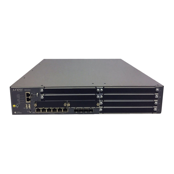
The services gateway provides cost-effective, scalable integration of routing, security, and other mid-range applications for these sites. The SRX550 Services Gateway has a modular 2U chassis that fits a 19-inch rack with a depth of approximately 18.1 inches. Figure 1 on page 3... -
Page 19: Srx550 Services Gateway Hardware Features
RELATED DOCUMENTATION SRX550 Services Gateway Chassis | 14 Accessing the SRX550 Services Gateway | 11 SRX550 Services Gateway Software Features and Licenses | 4 SRX550 Services Gateway Hardware Features The SRX550 Services Gateway provides the following features: Symmetric Multiprocessing-based data forwarding. -
Page 20: Srx550 Services Gateway Software Features And Licenses
RELATED DOCUMENTATION SRX550 Services Gateway Description | 2 Accessing the SRX550 Services Gateway | 11 SRX550 Services Gateway Software Features and Licenses | 4 SRX550 Services Gateway Chassis | 14 Physical Interface Modules SRX550 Services Gateway Software Features and Licenses... - Page 21 Table 3: Software Features and Licenses Feature Category Feature Routing OSPF Routing Information Protocol version 1 (RIPv1) and version 2 (RIPv2) Static routes Intermediate System-to-Intermediate System (IS-IS) Connectionless Network Service (CLNS): End System-to-Intermediate System (ES-IS) protocol IS-IS extensions BGP extensions Static routes NOTE: CLNS is available only in packet-based mode.
- Page 22 Table 3: Software Features and Licenses (continued) Feature Category Feature Encapsulation Ethernet: Media access control (MAC) encapsulation 802.1p tagging Point-to-Point Protocol over Ethernet (PPPoE) Circuit cross-connect (CCC) Translational cross-connect (TCC) Synchronous Point-to-Point Protocol (PPP) Frame Relay High-Level Data Link Control (HDLC) 802.1Q filtering and forwarding Multilink Frame Relay (MLFR) Multilink PPP...
- Page 23 Table 3: Software Features and Licenses (continued) Feature Category Feature Security IPsec VPN for site-to-site or remote access encrypted tunneling Antivirus filtering, including full antivirus file-based scanning or Express-AV packet-based scanning Antispam and anti-phishing filtering Web filtering Content filtering based on file types and types of files within HTTP and HTTPS Unified threat management (UTM) Network attack detection Denial of service (DoS) and distributed denial of service (DDoS) protection...
- Page 24 Table 3: Software Features and Licenses (continued) Feature Category Feature System Junos XML protocol XML application programming interface (API) management The J-Web browser interface—For services gateway configuration and management Junos OS command-line interface (CLI)—For services gateway configuration and management through the console through Telnet, or SSH Simple Network Management Protocol version 1 (SNMPv1), SNMPv2, and SNMPv3 Network and Security Manager (NSM) J-Flow flow monitoring and accounting...
-
Page 25: Srx550 Services Gateway Power Over Ethernet
Ethernet LAN cable. The SRX550 Services Gateway provides PoE ports, which supply electric power over the same ports that are used to connect network devices. PoE ports allow you to plug in devices that require both network connectivity and electric power, such as Voice over IP (VoIP) and IP phones and wireless access points. - Page 26 GPIMs connected on the designated PoE ports. Table 4 on page 10 lists the SRX550 Services Gateway PoE specifications. Table 4: SRX550 Services Gateway PoE Specifications Power Management Schemes...
-
Page 27: Accessing The Srx550 Services Gateway
The J-Web interface provides access to all Junos OS functionality and features. Junos OS command-line interface (CLI): Juniper Networks command shell that runs on top of a UNIX-based operating system kernel. The CLI is a straightforward command interface. On a single line, you type commands that are executed when you press the Enter key. -
Page 28: Hardware Component Overview
SRX550 Services Gateway Boot Devices and Dual-Root Partitioning Scheme | 12 SRX550 Services Gateway Boot Devices and Dual-Root Partitioning Scheme By default, the SRX550 Services Gateway boots from the following storage media (in order of priority): 1. Internal CompactFlash card (default; always present) 2. - Page 29 RELATED DOCUMENTATION Installation Overview for the SRX550 Services Gateway | 60 Required Tools and Parts for Installing the SRX550 Services Gateway | 61 SRX550 Services Gateway Basic Connectivity Overview | 95...
-
Page 30: Chassis Description
SRX550 Services Gateway Front Panel LEDs | 19 SRX550 Services Gateway Back Panel | 22 SRX550 Services Gateway Chassis The SRX550 Services Gateway chassis is a rigid sheet metal structure that houses all the other hardware components. Table 5 on page 14 provides information about the physical specifications for the services gateway. -
Page 31: Srx550 Services Gateway Front Panel
General Electrical Safety Guidelines and Warnings SRX550 Services Gateway Front Panel Figure 2 on page 15 shows the front panel of the SRX550 Services Gateway. Figure 2: SRX550 Services Gateway Front Panel Table 6 on page 15 provides information about the front panel components of the services gateway with... - Page 32 Table 6: SRX550 Services Gateway Front Panel Components (continued) Number Component Location Description Serial Console Port Left side of the Connects a laptop to the services gateway for CLI front chassis management. The port uses an RJ-45 serial connection, panel is configured as data terminal equipment (DTE), and supports the RS-232 (EIA-232) standard.
- Page 33 Table 6: SRX550 Services Gateway Front Panel Components (continued) Number Component Location Description USB 0 and USB 1 Left side of the The services gateway has two USB ports, labeled USB ports front chassis 0 and USB 1, that accept a USB storage device. These panel USB ports accept USB flash drives with Type A plugs.
- Page 34 Table 6: SRX550 Services Gateway Front Panel Components (continued) Number Component Location Description 6 fixed Gigabit Left side of the The Gigabit Ethernet ports have the following Ethernet ports: front chassis characteristics: panel, lower edge Port labeled 0/0 Use an RJ-45 connector.
-
Page 35: Srx550 Services Gateway Front Panel Leds
Figure 3 on page 19 shows how the slots on the front panel of the SRX550 Services Gateway are numbered. Figure 3: SRX550 Services Gateway Slot Numbers RELATED DOCUMENTATION SRX550 Services Gateway Front Panel LEDs | 19 SRX550 Services Gateway Chassis | 14... - Page 36 Table 7: SRX550 Services Gateway Front Panel LEDs Label LED State Color Description ALARM On Steadily Amber Indicates a major alarm, such as low Services Processing Unit (SPU) memory (less than 10% remaining), session full, maximum number of VPN tunnels reached, high availability (HA) status changed, or redundant group member not found.
- Page 37 Table 7: SRX550 Services Gateway Front Panel LEDs (continued) Label LED State Color Description Steadily on Green All configured high availability links are available. High availability links are not working as expected and a cluster member might be missing or unreachable.
-
Page 38: Srx550 Services Gateway Back Panel
SRX550 Services Gateway. Figure 5: SRX550 Services Gateway Back Panel Table 8 on page 22 describes the components on the back panel of the SRX550 Services Gateway with reference to Figure 5 on page... - Page 39 Table 8: SRX550 Services Gateway Back Panel Components (continued) Number Component Location Description Usage ACE Slot Top center of NOTE: This slot is not used. the back panel Grounding point Left side of the Contains two M4 screws that Connects the services...
-
Page 40: Interface Module Description
When installing the 24-Port Gigabit Ethernet XPIM, which uses four slots, you must install it in the 20-gigabit GPIM slot 6, which refers to the top four slots 5 through 8. Figure 6 on page 25 shows how the slots on the front panel of the SRX550 Services Gateway are numbered. - Page 41 Figure 6: SRX550 Services Gateway Slot Numbers CAUTION: SRX550 Services Gateway does not support hot-swappable functionality for GPIMs. For more information about supported GPIMs and the minimum supported Junos OS release, see SRX Series Services Gateway Interface Modules and Compatibility...
-
Page 42: Srx550 Services Gateway Mini-Physical Interface Modules
Physical Interface Modules SRX550 Services Gateway Mini-Physical Interface Modules The SRX550 Services Gateway has two slots for installing Mini-Physical Interface Modules (Mini-PIMs). A Mini-PIM is a network interface card that is installed in the services gateway to provide physical connections to a LAN or WAN. The Mini-PIMs supported on the services gateway are field-replaceable units (FRUs);... -
Page 43: Cooling System Description
SRX550 Services Gateway Cooling System | 27 SRX550 Services Gateway Cooling System The SRX550 Services Gateway cooling system consists of four fixed fans. The fans provide cooling to the components installed in the services gateway. To function properly, the entire cooling system requires an unobstructed airflow and proper clearance around the site. -
Page 44: Power System Description
SRX550 Services Gateway Power Supply | 28 SRX550 Services Gateway Power Supply The SRX550 Services Gateway uses either one AC or one DC power supply unit (PSU). The services gateway is equipped with one AC power supply (see Figure 10 on page 29) for non-power redundancy. - Page 45 Figure 10: AC Power Supply Figure 11: DC Power Supply The power supplies provide different output wattage to the services gateway components according to the voltage requirements of the components. The power supply components are listed in Table 9 on page...
- Page 46 Table 9: Component Power Output/Consumption Power Supply Output/Consumption 645 W AC power supply This power supply can provide: 390 W at 12 V 255 W PoE on a single power supply, or with redundancy using the two power supplies 510 W PoE using the two power supply option operating as nonredundant NOTE: Using the two power supply option operating as nonredundant...
- Page 47 RELATED DOCUMENTATION SRX550 Services Gateway Chassis | 14 SRX550 Services Gateway Front Panel | 15 SRX550 Services Gateway Back Panel | 22 SRX550 Services Gateway Cooling System | 27 Troubleshooting the Power System on the SRX550 Services Gateway | 130...
-
Page 48: Site Planning And Specifications
PART Site Planning and Specifications Planning and Preparing the Site | 33 Rack Requirements | 38 Cabinet Requirements | 47 Power Requirements and Specifications | 49 Cable Specifications and Pinouts | 56... -
Page 49: Planning And Preparing The Site
Planning and Preparing the Site IN THIS CHAPTER Site Preparation Checklist for the SRX550 Services Gateway | 33 General Site Installation Guidelines for the SRX550 Services Gateway | 35 SRX550 Services Gateway Environmental Specifications | 36 Site Preparation Checklist for the SRX550 Services Gateway... - Page 50 Table 11: Site Preparation Checklist for SRX550 Services Gateway Installation (continued) Performed Item or Task Additional Information Date Notes Verify that “SRX550 Services Gateway Environmental environmental factors Specifications” on page 36 such as temperature and humidity do not exceed device tolerances.
-
Page 51: General Site Installation Guidelines For The Srx550 Services Gateway
General Site Installation Guidelines for the SRX550 Services Gateway | 35 General Site Installation Guidelines for the SRX550 Services Gateway The following precautions help you plan an acceptable operating environment for your SRX550 Services Gateway and avoid environmentally caused equipment failures: For the cooling system to function properly, the airflow around the chassis must be unrestricted. -
Page 52: Srx550 Services Gateway Environmental Specifications
SRX550 Services Gateway Cabinet Size and Clearance Requirements | 47 SRX550 Services Gateway Rack Size and Strength Requirements | 43 Clearance Requirements for Airflow and Hardware Maintenance of the SRX550 Services Gateway | 45 SRX550 Services Gateway Environmental Specifications Table 12 on page 36 provides the required environmental conditions for normal SRX550 Services Gateway operations. - Page 53 Install the services gateway only in restricted areas, such as dedicated equipment rooms and equipment closets, in accordance with Articles 110–16, 110–17, and 110–18 of the National Electrical Code, ANSI/NFPA 70. RELATED DOCUMENTATION SRX550 Services Gateway General Safety Guidelines and Warnings Routine Maintenance Procedures for the SRX550 Services Gateway | 123...
-
Page 54: Rack Requirements
SRX550 Services Gateway Rack Size and Strength Requirements | 43 SRX550 Services Gateway Spacing of Mounting Bracket and Flange Holes | 44 Clearance Requirements for Airflow and Hardware Maintenance of the SRX550 Services Gateway | 45 Rack-Mounting Requirements and Warnings Ensure that the equipment rack into which the services gateway is installed is evenly and securely supported to avoid hazardous conditions that could result from uneven mechanical loading. - Page 56 De onderstaande richtlijnen worden verstrekt om uw veiligheid te verzekeren: De Juniper Networks services gateway moet in een stellage worden geïnstalleerd die aan een bouwsel is verankerd. Dit toestel dient onderaan in het rek gemonteerd te worden als het toestel het enige in het rek is.
- Page 57 Les directives ci-dessous sont destinées à assurer la protection du personnel: Le rack sur lequel est monté le Juniper Networks services gateway doit être fixé à la structure du bâtiment. Si cette unité constitue la seule unité montée en casier, elle doit être placée dans le bas.
- Page 58 Il Juniper Networks services gateway deve essere installato in un telaio, il quale deve essere fissato alla struttura dell'edificio. Questa unità deve venire montata sul fondo del supporto, se si tratta dell'unica unità da montare nel supporto. Quando questa unità viene montata in un supporto parzialmente pieno, caricare il supporto dal basso all'alto, con il componente più...
-
Page 59: Srx550 Services Gateway Rack Size And Strength Requirements
SRX550 Services Gateway Rack Size and Strength Requirements When installing the SRX550 Services Gateway in a rack, you must ensure that the rack complies with a 2U (19 in. or 45.6 cm) rack as defined in Cabinets, Racks, Panels, and Associated Equipment (document number EIA-310-D) published by the Electronic Industries Alliance (http://www.ecaus.org/eia/site/index.html). -
Page 60: Srx550 Services Gateway Spacing Of Mounting Bracket And Flange Holes
SRX550 Services Gateway Cabinet Size and Clearance Requirements | 47 Site Preparation Checklist for the SRX550 Services Gateway | 33 SRX550 Services Gateway Spacing of Mounting Bracket and Flange Holes | 44 Connecting the SRX550 Services Gateway to the Building Structure | 68... -
Page 61: Clearance Requirements For Airflow And Hardware Maintenance Of The Srx550 Services Gateway
Clearance Requirements for Airflow and Hardware Maintenance of the SRX550 Services Gateway When planning the installation site for the SRX550 Services Gateway, you need to allow sufficient clearance around the rack. When planning the installation site for the services gateway, consider the following: For the cooling system to function properly, the airflow around the chassis must be unrestricted. - Page 62 SRX550 Services Gateway Cabinet Size and Clearance Requirements | 47 Site Preparation Checklist for the SRX550 Services Gateway | 33 SRX550 Services Gateway Rack Size and Strength Requirements | 43 General Site Installation Guidelines for the SRX550 Services Gateway | 35...
-
Page 63: Cabinet Requirements
SRX550 Services Gateway Cabinet Airflow Requirements | 48 SRX550 Services Gateway Cabinet Size and Clearance Requirements You can install the SRX550 Services Gateway in a 19 in. (48.3 cm) cabinet as defined in Cabinets, Racks, Panels, and Associated Equipment (document number EIA-310-D) published by the Electronic Industries Alliance (http://www.ecaus.org/eia/site/index.html). -
Page 64: Srx550 Services Gateway Cabinet Airflow Requirements
Clearance Requirements for Airflow and Hardware Maintenance of the SRX550 Services Gateway | 45 SRX550 Services Gateway Cabinet Airflow Requirements When you mount the SRX550 Services Gateway in a cabinet, you must ensure that ventilation through the cabinet is sufficient to prevent overheating. Consider the following when planning for chassis cooling: Ensure that the cool air supply you provide through the cabinet can adequately dissipate the thermal output of the services gateway. -
Page 65: Power Requirements And Specifications
SRX550 Services Gateway Electrical Wiring Guidelines | 49 SRX550 Services Gateway Supported AC Power Cords | 51 SRX550 Services Gateway AC Power Supply Electrical Specifications | 52 SRX550 Services Gateway DC Power Cable Specifications | 53 SRX550 Services Gateway DC Power Supply Electrical Specifications | 54... - Page 66 Table 14: Site Electrical Wiring Guidelines for the SRX550 Services Gateway Site Wiring Factor Guideline Signaling limitations To ensure that signaling functions optimally: Install wires correctly. Improperly installed wires can emit radio interference. Do not exceed the recommended distances or pass wires between buildings.
-
Page 67: Srx550 Services Gateway Supported Ac Power Cords
RELATED DOCUMENTATION General Site Installation Guidelines for the SRX550 Services Gateway | 35 Maintaining the SRX550 Services Gateway Power Supply | 123 SRX550 Services Gateway Power Requirements | 54 SRX550 Services Gateway Environmental Specifications | 36 SRX550 Services Gateway Supported AC Power Cords... -
Page 68: Srx550 Services Gateway Ac Power Supply Electrical Specifications
RELATED DOCUMENTATION SRX550 Services Gateway Power Supply | 28 Clearance Requirements for Airflow and Hardware Maintenance of the SRX550 Services Gateway | 45 SRX550 Services Gateway Electrical Wiring Guidelines | 49 Site Preparation Checklist for the SRX550 Services Gateway | 33... -
Page 69: Srx550 Services Gateway Dc Power Cable Specifications
RELATED DOCUMENTATION SRX550 Services Gateway Power Supply | 28 Clearance Requirements for Airflow and Hardware Maintenance of the SRX550 Services Gateway | 45 SRX550 Services Gateway Electrical Wiring Guidelines | 49 Site Preparation Checklist for the SRX550 Services Gateway | 33... -
Page 70: Srx550 Services Gateway Dc Power Supply Electrical Specifications
Site Preparation Checklist for the SRX550 Services Gateway | 33 SRX550 Services Gateway Power Requirements The electrical and power requirements for the SRX550 Services Gateway include factors you must consider while planning the electrical wiring and power availability at your site. These requirements are covered in... - Page 71 RELATED DOCUMENTATION SRX550 Services Gateway Power Supply | 28 Clearance Requirements for Airflow and Hardware Maintenance of the SRX550 Services Gateway | 45 Site Preparation Checklist for the SRX550 Services Gateway | 33 SRX550 Services Gateway Electrical Wiring Guidelines | 49...
-
Page 72: Cable Specifications And Pinouts
Cable Specifications and Pinouts IN THIS CHAPTER Interface Cabling and Wiring Specifications for the SRX550 Services Gateway | 56 RJ-45 Connector Pinouts for the SRX550 Services Gateway Ethernet Port | 57 RJ-45 Connector Pinouts for the SRX550 Services Gateway Console Port | 58... -
Page 73: Connector Pinouts For The Srx550 Services Gateway Ethernet Port
RELATED DOCUMENTATION RJ-45 Connector Pinouts for the SRX550 Services Gateway Ethernet Port | 57 RJ-45 Connector Pinouts for the SRX550 Services Gateway Console Port | 58 RJ-45 Connector Pinouts for the SRX550 Services Gateway Ethernet Port The port on the front panel labeled ETHERNET is an autosensing 10/100-Mbps Ethernet RJ-45 receptacle that accepts an Ethernet cable for connecting the services gateway to a management LAN (or other device that supports out-of-band management). -
Page 74: Connector Pinouts For The Srx550 Services Gateway Console Port
Signal Ground Ground Signal Ground Receive Data DSR/DCD Data Set Ready Clear to Send RELATED DOCUMENTATION RJ-45 Connector Pinouts for the SRX550 Services Gateway Ethernet Port | 57 Interface Cabling and Wiring Specifications for the SRX550 Services Gateway | 56... -
Page 75: Initial Installation And Configuration
Installing the Mounting Hardware | 67 Installing the Services Gateway | 69 Grounding the SRX550 Services Gateway | 76 Connecting the SRX550 Services Gateway to External Devices | 79 Providing Power to the SRX550 Services Gateway | 87 Performing Initial Configuration | 95... -
Page 76: Installation Overview
Installation Overview for the SRX550 Services Gateway After you have prepared the site for installation and unpacked the SRX550 Services Gateway, you are ready to install the device. It is important to proceed through the installation process in the following order: 1. -
Page 77: Required Tools And Parts For Installing The Srx550 Services Gateway
Preparing the SRX550 Services Gateway for Rack-Mount Installation | 67 Installing the SRX550 Services Gateway in a Rack | 69 Grounding the SRX550 Services Gateway | 77 Powering On the SRX550 Services Gateway | 93 Required Tools and Parts for Installing the SRX550 Services Gateway... -
Page 78: Installation Instructions Warning
SRX550 Services Gateway Fire Safety Requirements and Fire Suppression Equipment SRX550 Services Gateway Autoinstallation Overview Autoinstallation provides automatic configuration for a new SRX550 Services Gateway that you connect to the network and turn on, or for a services gateway configured for autoinstallation. The autoinstallation... - Page 79 Initial Configuration for Security Devices. RELATED DOCUMENTATION Installation Overview for the SRX550 Services Gateway | 60 Required Tools and Parts for Installing the SRX550 Services Gateway | 61 Grounding the SRX550 Services Gateway | 77 SRX550 Services Gateway Basic Connectivity Overview | 95...
-
Page 80: Unpacking The Services Gateway
1/2 in. (13 mm) open-end or socket wrench to remove bracket bolts from the shipping pallet Blank panels to cover any slots not occupied by a component The SRX550 Services Gateway is shipped in a cardboard carton and secured with foam packing material. The carton also contains an accessory box and quick start instructions. -
Page 81: Verifying Parts Received With The Srx550 Services Gateway
Component Quantity 2U SRX550 Services Gateway chassis with 6 GPIM slots, 2 Mini-PIM slots, 1 ACE slot, 2 power supply slots, 6 10/100/1000 base-T ports, and 4 Gigabit Ethernet SFP ports. Includes blank covers for GPIM slots (6 covers for GPIM slots), Mini-PIM slots, ACE slot, and power supply slots. - Page 82 Table 22: Parts List for a Fully Configured SRX550 Services Gateway (continued) Component Quantity Front-mount and mid-mount rack-mount kit Serial console cable with DB-9 and RJ-45 connectors USB console cable with Type-A and Mini-B USB plugs 645 W AC power supply that provides: 390 W system power at 12 V; 255 W PoE power on a single power supply, or with redundancy using the two power supply option;...
-
Page 83: Installing The Mounting Hardware
Verify that the site meets the requirements described in “Site Preparation Checklist for the SRX550 Services Gateway” on page Verify that you have the following parts available in your rack-mounting kit for the SRX550 Services Gateway: Rack-mounting brackets Eight mounting screws to attach the mounting brackets to the chassis of the services gateway... -
Page 84: Connecting The Srx550 Services Gateway To The Building Structure
Connecting the SRX550 Services Gateway to the Building Structure Always secure the rack in which you are installing the SRX550 Services Gateway to the structure of the building. If your geographical area is subject to earthquakes, bolt the rack to the floor. For maximum stability, also secure the rack to ceiling brackets. -
Page 85: Installing The Services Gateway
Installing a DC Power Supply on the SRX550 Services Gateway | 73 Installing the SRX550 Services Gateway in a Rack You can front-mount the SRX550 Services Gateway in a rack. Many types of racks are acceptable, including four-post (telco) racks, enclosed cabinets, and open-frame racks. - Page 86 Figure 14: Installing the Rack Mount Brackets (Front Mount Position) Figure 15: Installing the Rack Mount Brackets (Center Mount Position) 3. Have one person grasp the sides of the services gateway, lift it, and position it in the rack. 4. Align the bottom hole in each mounting bracket with a hole in each rack rail, making sure the chassis is level.
- Page 87 RELATED DOCUMENTATION Installation Overview for the SRX550 Services Gateway | 60 SRX550 Services Gateway Rack Size and Strength Requirements | 43 SRX550 Services Gateway Spacing of Mounting Bracket and Flange Holes | 44...
-
Page 88: Installing An Ac Power Supply On The Srx550 Services Gateway
5. Attach the power cord to the AC power source, and switch on the dedicated facility circuit breaker for the power supply. Follow the ESD and connection instructions for your site. If the power supply is correctly installed and functioning normally, the POWER LED lights steadily. Figure 17: Installing an AC Power Supply on the SRX550 Services Gateway... -
Page 89: Installing A Dc Power Supply On The Srx550 Services Gateway
3. Orient the power supply so that the locking lever is on the left, as shown in Figure 18 on page Figure 18: Installing a DC Power Supply on an SRX550 Services Gateway 4. Using both hands, slide the power supply straight into the chassis until the power supply is fully seated in the chassis slot. - Page 90 7. Verify that the DC power cables are correctly labeled before making connections to the power supply. In a typical power distribution scheme where the return is connected to chassis ground at the battery plant, you can use a multimeter to verify the resistance of the –48V and RTN DC cables to chassis ground: The cable with very large resistance (indicating an open circuit) to chassis ground will be –48V.
- Page 91 Figure 19: Connecting DC Power Cables 9. Replace the clear plastic cover over the terminal studs on the faceplate. 10. Verify that the power cables are connected correctly, that they are not touching or blocking access to services gateway components, and that they do not drape where people could trip on them. 11.
-
Page 92: Grounding The Srx550 Services Gateway
SRX550 Services Gateway Grounding Specifications To meet safety and electromagnetic interference (EMI) requirements and to ensure proper operation, the SRX550 Services Gateway must be adequately grounded before power is connected. You must provide a grounding lug to connect the services gateway to earth ground. -
Page 93: Grounding The Srx550 Services Gateway
RELATED DOCUMENTATION Grounding the SRX550 Services Gateway | 77 Connecting the SRX550 Services Gateway to a DC Power Source | 90 Powering On the SRX550 Services Gateway | 93 Powering Off the SRX550 Services Gateway | 94 Grounding the SRX550 Services Gateway... - Page 94 Preventing Electrostatic Discharge Damage to the SRX550 Services Gateway Powering On the SRX550 Services Gateway | 93 Powering Off the SRX550 Services Gateway | 94 Organizing Interface Cables on the SRX550 Services Gateway | 79 SRX550 Services Gateway General Safety Guidelines and Warnings...
-
Page 95: Connecting The Srx550 Services Gateway To External Devices
Connecting the Modem to the Console Port on the SRX550 Services Gateway | 80 Connecting to the SRX550 Services Gateway from the CLI with the USB Console Port | 81 Connecting the CLI at the User End for the SRX550 Services Gateway | 83... -
Page 96: Connecting The Modem To The Console Port On The Srx550 Services Gateway
Connecting the Modem to the Console Port on the SRX550 Services Gateway To connect the dial-up modem to the console port on the SRX550 Services Gateway: 1. Turn off power to the services gateway. 2. Turn off the power to the modem. -
Page 97: Connecting To The Srx550 Services Gateway From The Cli With The Usb Console Port
Connecting to the SRX550 Services Gateway from the CLI Remotely | 104 Configuring the Modem at the SRX550 Services Gateway End | 85 Connecting the CLI at the User End for the SRX550 Services Gateway | 83 Connecting to the SRX550 Services Gateway from the CLI with the USB... - Page 98 1. If you have not already done so, obtain the USB console driver software from the Juniper Networks website Silicon Labs website. 2. Install the USB console driver software by following these steps: CAUTION: Install the USB console driver software before attempting to establish a physical connection between the services gateway and the management device, otherwise the connection will fail.
-
Page 99: Connecting The Cli At The User End For The Srx550 Services Gateway
Connecting to the SRX550 Services Gateway from the CLI Remotely | 104 Connecting the CLI at the User End for the SRX550 Services Gateway To connect to the CLI through a dial-up modem connected to the console port on the SRX550 Services Gateway: 1. - Page 100 RELATED DOCUMENTATION Connecting to the SRX550 Services Gateway from the CLI Remotely | 104 Configuring the Modem at the SRX550 Services Gateway End | 85 Connecting the Modem to the Console Port on the SRX550 Services Gateway | 80...
-
Page 101: Configuring The Modem At The Srx550 Services Gateway End
Configuring the Modem at the SRX550 Services Gateway End Before you can connect a dial-up modem to the console port on the SRX550 Services Gateway, you must configure the modem to accept a call on the first ring and to accept DTR signals. You must also disable flow control on the modem. - Page 102 Connecting to the SRX550 Services Gateway from the CLI Remotely | 104 Connecting the Modem to the Console Port on the SRX550 Services Gateway | 80 Connecting the CLI at the User End for the SRX550 Services Gateway | 83...
-
Page 103: Providing Power To The Srx550 Services Gateway
A 645 W AC power supply with PoE support ships with the SRX550 Services Gateway. You connect AC power to the services gateway by attaching the power cord from the AC power source to the AC appliance inlet located on the power supply. - Page 104 CAUTION: We recommend using a surge protector for the power connection. RELATED DOCUMENTATION Preventing Electrostatic Discharge Damage to the SRX550 Services Gateway Grounding the SRX550 Services Gateway | 77...
-
Page 105: Connecting An Ac Power Cord To The Srx550 Services Gateway
2. Connect the power cord to the power supply, as shown in Figure 23 on page Figure 23: Connecting an AC Power Cord on the SRX550 Services Gateway 3. Insert the power cord plug into an external AC power source receptacle. -
Page 106: Connecting The Srx550 Services Gateway To A Dc Power Source
Do not mix AC and DC power supplies within the same services gateway. Damage to the device might occur. A 645 W DC power supply with PoE support is available for the SRX550 Services Gateway. WARNING: Before performing the following procedure, ensure that power is removed from the DC circuit. - Page 107 NOTE: The DC cable should be of minimum 14 AWG. CAUTION: You must ensure that power connections maintain the proper polarity. The power source cables might be labeled (+) and (–) to indicate their polarity. There is no standard color coding for DC power cables. The color coding used by the external DC power source at your site determines the color coding for the leads on the power cables that attach to the terminals on the power supply.
-
Page 108: Grounding The Srx550 Services Gateway | 77
The services gateway must be connected to earth ground during normal operation. The protective earthing terminal on the back panel of the chassis is provided to connect the services gateway to ground. RELATED DOCUMENTATION Preventing Electrostatic Discharge Damage to the SRX550 Services Gateway Grounding the SRX550 Services Gateway | 77... -
Page 109: Powering On The Srx550 Services Gateway
RELATED DOCUMENTATION Connecting the SRX550 Services Gateway to the AC Power Source | 87 Connecting the SRX550 Services Gateway to a DC Power Source | 90 Grounding the SRX550 Services Gateway | 77... -
Page 110: Powering Off The Srx550 Services Gateway
To power off the services gateway, press the Power button on the front of the services gateway and hold it for 10 seconds. The services gateway immediately shuts down. NOTE: Graceful shutdown is not supported on the SRX550 Services Gateway. To remove power completely from the services gateway, unplug the AC power cord or DC power supply cable. -
Page 111: Performing Initial Configuration
Management Access for the SRX550 Services Gateway | 119 SRX550 Services Gateway Basic Connectivity Overview The Juniper Networks Junos operating system (Junos OS) is preinstalled on the SRX550 Services Gateway. When the services gateway is powered on, it is ready to be configured. - Page 112 RELATED DOCUMENTATION SRX550 Services Gateway Basic Connectivity Settings | 97 Connecting to the SRX550 Services Gateway from the J-Web Interface | 98 Connecting to the SRX550 Services Gateway from the CLI Locally | 102 Connecting to the SRX550 Services Gateway from the CLI Remotely | 104...
-
Page 113: Srx550 Services Gateway Basic Connectivity Settings
SRX550 Services Gateway Basic Connectivity Settings Table 29 on page 97 provides information on basic connectivity settings for the SRX550 Services Gateway. Table 29: Services Gateway Basic Connectivity Settings Details Element Description Settings Device The hostname defines the network or network... -
Page 114: Connecting To The Srx550 Services Gateway From The J-Web Interface
Connecting to the SRX550 Services Gateway from the CLI Remotely | 104 Connecting to the SRX550 Services Gateway from the J-Web Interface To use the J-Web setup wizard to configure the SRX550 Services Gateway, you must connect through one of the built-in Ethernet management ports. - Page 115 Figure 25 on page Figure 25: Connecting to the Ethernet Port on the SRX550 Services Gateway 1. From the management device (such as a desktop or laptop computer) that you use to access the J-Web interface, verify that the address of the port that you connect to the services gateway is set to one of the following: Ethernet address on the 192.168.1.0/24 network (other than 192.168.1.1)
- Page 116 “Configuring Basic Settings for the SRX550 Services Gateway with a Configuration Editor” on page 110. 12. Click Commit to apply the configuration. After configuring the basic settings, you are prompted to log...
-
Page 117: Srx550 Services Gateway Secure Web Access Overview
If you lose the connection through the management interface, you must connect through the console port. RELATED DOCUMENTATION Connecting to the SRX550 Services Gateway from the CLI Locally | 102 Connecting to the SRX550 Services Gateway from the CLI Remotely | 104 SRX550 Services Gateway Secure Web Access Overview You can manage a services gateway remotely through the J-Web interface. -
Page 118: Connecting To The Srx550 Services Gateway From The Cli Locally
Configuring Basic Settings for the SRX550 Services Gateway with a Configuration Editor | 110 Connecting to the SRX550 Services Gateway from the CLI Locally To use the CLI to configure the SRX550 Services Gateway, you must connect through the console port, as shown in Figure 27 on page 102. - Page 119 To connect to the CLI using a local management device through the console port on the services gateway: 1. Turn off power to the services gateway. 2. Turn off power to the management device (such as a desktop or laptop computer) that you are using to access the CLI.
-
Page 120: Connecting To The Srx550 Services Gateway From The Cli Remotely
Connecting to the SRX550 Services Gateway from the CLI Remotely | 104 Connecting to the SRX550 Services Gateway from the CLI Remotely You can connect an SRX550 Services Gateway to the CLI from a remote location through two dial-up modems:... - Page 121 srx550-factory.conf...
- Page 122 3. View the required default config file. user@host> file show /etc/config/config file name The following sample output displays the factory-default configuration on an SRX550 Services Gateway: ## $Id: $ ## Copyright (c) 2009-2011, Juniper Networks, Inc. ## All rights reserved.
- Page 123 web-management { http { interface [ vlan.0 ]; https { system-generated-certificate; interface [ vlan.0 ]; xnm-clear-text; name-server { 208.67.222.222; 208.67.220.220; syslog { archive size 100k files 3; interfaces { ge-0/0/0 { unit 0; ge-0/0/1 { unit 0 { family ethernet-switching { vlan { members vlan-trust;...
- Page 124 ge-0/0/3 { unit 0 { family ethernet-switching { vlan { members vlan-trust; ge-0/0/4 { unit 0 { family ethernet-switching { vlan { members vlan-trust; ge-0/0/5 { unit 0 { family ethernet-switching { vlan { members vlan-trust; vlan { unit 0 { family inet { address 192.168.1.1/24;...
- Page 125 ip { source-route-option; tear-drop; tcp { syn-flood { alarm-threshold 1024; attack-threshold 200; source-threshold 1024; destination-threshold 2048; timeout 20; land; zones { security-zone trust { host-inbound-traffic { system-services { all; protocols { all; interfaces { vlan.0; security-zone untrust { interfaces { ge-0/0/0.0 { host-inbound-traffic { system-services {...
-
Page 126: Configuring Basic Settings For The Srx550 Services Gateway With A Configuration Editor
RELATED DOCUMENTATION SRX550 Services Gateway Basic Connectivity Overview | 95 SRX550 Services Gateway Autoinstallation Overview | 62 Configuring Basic Settings for the SRX550 Services Gateway with a Configuration Editor To establish basic connectivity on an SRX550 Services Gateway: 1. Identify the services gateway. - Page 127 In a typical network, the services gateway has the basic settings listed in Table 31 on page 111. Determine the values to set on the services gateway in your network. Table 31: Sample Settings on the SRX550 Services Gateway SRX550 Services Gateway Property Sample Value Services gateway hostname...
- Page 128 Table 32: Configuring Basic Settings (continued) Required or Task Optional Using the J-Web Setup Wizard Using the CLI Identify the domain Required From the Configure System: Specify the domain name. name of the network or Identification page, type the domain For example: network to which the name of the services gateway;...
- Page 129 Table 32: Configuring Basic Settings (continued) Required or Task Optional Using the J-Web Setup Wizard Using the CLI Add each domain to Optional From the Configure System: Specify the domains to be which the services Network Settings page, type the searched.
- Page 130 Devices. RELATED DOCUMENTATION Connecting to the SRX550 Services Gateway from the CLI Remotely | 104 Configuring the Modem at the SRX550 Services Gateway End | 85 Connecting the Modem to the Console Port on the SRX550 Services Gateway | 80...
-
Page 131: Displaying Basic Connectivity Configurations For The Srx550 Services Gateway
Displaying Basic Connectivity Configurations for the SRX550 Services Gateway To verify that the SRX550 Services Gateway has the settings you configured, you need to display the basic connectivity configurations. Because the basic connectivity settings appear in different places in the configuration hierarchy, displaying the entire configuration at once makes viewing the settings easier. -
Page 132: Built-In Ethernet Ports For The Srx550 Services Gateway
Connecting to the SRX550 Services Gateway from the CLI Remotely | 104 Connecting to the SRX550 Services Gateway from the J-Web Interface | 98 Configuring Basic Settings for the SRX550 Services Gateway with a Configuration Editor | 110 Built-In Ethernet Ports for the SRX550 Services Gateway You perform initial device setup through the six built-in Gigabit Ethernet ports, labeled 0/0 through 0/5 (interfaces ge-0/0/0 through ge-0/0/5), on the front panel of the SRX550 Services Gateway. - Page 133 the interface ge-0/0/0. All interfaces are configured as Layer 3 interfaces. See Table 33 on page 117 the default interface configuration. Table 33: Default Interface Configuration for the Services Gateway Security DHCP Port Label Interface Connector Zone State Address ge-0/0/0 RJ-45 Untrust Client...
- Page 134 Table 33: Default Interface Configuration for the Services Gateway (continued) Security DHCP Port Label Interface Connector Zone State Address ge-0/0/4 RJ-45 Trust Server ge-0/0/5 RJ-45 Trust Server ge-0/0/6 No default Configuration ge-0/0/7 ge-0/0/8 ge-0/0/9 By default, the security policies and NAT rules in Table 34 on page 118 Table 35 on page 118 are created...
-
Page 135: Management Access For The Srx550 Services Gateway
SRX550 Services Gateway Basic Connectivity Overview | 95 Management Access for the SRX550 Services Gateway Telnet allows you to connect to the SRX550 Services Gateway and access the CLI to execute commands from a remote system. Telnet connections are not encrypted and therefore can be intercepted. - Page 136 RELATED DOCUMENTATION SRX550 Services Gateway Basic Connectivity Overview | 95 Connecting to the SRX550 Services Gateway from the J-Web Interface | 98 Connecting to the SRX550 Services Gateway from the CLI Locally | 102 Connecting to the SRX550 Services Gateway from the CLI Remotely | 104...
-
Page 137: Maintaining And Troubleshooting Components
PART Maintaining and Troubleshooting Components Maintaining Components | 122 Troubleshooting Components | 125... -
Page 138: Maintaining Components
CHAPTER 20 Maintaining Components IN THIS CHAPTER Required Tools and Parts for Maintaining the SRX550 Services Gateway Hardware Components | 122 Routine Maintenance Procedures for the SRX550 Services Gateway | 123 Maintaining the SRX550 Services Gateway Cooling System Components | 123... -
Page 139: Routine Maintenance Procedures For The Srx550 Services Gateway
Check the status LEDs on the front and back panels of the services gateway. RELATED DOCUMENTATION Required Tools and Parts for Maintaining the SRX550 Services Gateway Hardware Components | 122 Maintaining the SRX550 Services Gateway Cooling System Components | 123... - Page 140 RELATED DOCUMENTATION Required Tools and Parts for Maintaining the SRX550 Services Gateway Hardware Components | 122 Routine Maintenance Procedures for the SRX550 Services Gateway | 123...
-
Page 141: Troubleshooting Components
Troubleshooting with the CLI on the SRX550 Services Gateway | 125 Troubleshooting with LEDs on the SRX550 Services Gateway | 126 Troubleshooting with Chassis and Interface Alarm Messages on the SRX550 Services Gateway | 128 Troubleshooting the Power System on the SRX550 Services Gateway | 130... -
Page 142: Troubleshooting With Leds On The Srx550 Services Gateway
Troubleshooting with LEDs on the SRX550 Services Gateway The LEDs available on the services gateway display the status of various components. Table 36 on page 126 describes the LEDs on the chassis. Table 36: Component LEDs on the Services Gateway Chassis... - Page 143 Table 36: Component LEDs on the Services Gateway Chassis (continued) Location Usage Left side of the front The HA LED has the following indicator colors: chassis panel Green and steadily on indicates all configured high availability links are available. Red and steadily on indicates cluster member missing or unreachable.
-
Page 144: Troubleshooting With Chassis And Interface Alarm Messages On The Srx550 Services Gateway | 128
SRX550 Services Gateway Front Panel | 15 Troubleshooting with the CLI on the SRX550 Services Gateway | 125 Troubleshooting with Chassis and Interface Alarm Messages on the SRX550 Services Gateway | 128 Troubleshooting the Power System on the SRX550 Services Gateway | 130... - Page 145 If you did not configure the services gateway to boot from an alternative boot device, contact JTAC. Gigabit-Backplane Physical A GPIM has failed. Contact JTAC. Red (major) Interface Module (GPIM) “Juniper Networks Technical Assistance Center” on page 138...
-
Page 146: Troubleshooting The Power System On The Srx550 Services Gateway
Monitoring and Troubleshooting for Security Devices. Troubleshooting the Power System on the SRX550 Services Gateway The LEDs on the services gateway enable you to determine the performance and operation of the power system. The POWER LED located on the front panel of the services gateway, as described in... - Page 147 PSUs. problem or need additional assistance while troubleshooting a services gateway, open a support case using the Case Manager link at https://www.juniper.net/support/, or call 1-888-314-JTAC (within the United States) or 1-408-745-9500 (outside the United States). Amber Power button has been Once the services gateway is running pressed.
- Page 148 Table 38: POWER LED Description (continued) LED Status LED State Meaning Possible Cause and Corrective Action Indicates that the services If a red alarm condition occurs, issue the gateway is not receiving show chassis alarms command to power. determine the source of the problem. Verify that the AC power cord and/or DC power supply cable is not damaged.
- Page 149 Table 39: Power Supply Faceplate LEDs Power Supply Possible Cause and Corrective Type Label Color Meaning Action DC OK Green The DC output voltages produced Normal indication. No action is by the power supply are within required. tolerance. One or more of the DC output voltages produced by the power supply are outside of tolerance.
-
Page 150: Using The Reset Config Button On The Srx550 Services Gateway
Troubleshooting with the CLI on the SRX550 Services Gateway | 125 Troubleshooting with LEDs on the SRX550 Services Gateway | 126 Changing the RESET CONFIG Button Behavior on the SRX550 Services Gateway | 136 Using the RESET CONFIG Button on the SRX550 Services Gateway... - Page 151 Troubleshooting with LEDs on the SRX550 Services Gateway | 126 Troubleshooting the Power System on the SRX550 Services Gateway | 130 Changing the RESET CONFIG Button Behavior on the SRX550 Services Gateway | 136 Resetting the SRX550 Services Gateway | 137...
-
Page 152: Changing The Reset Config Button Behavior On The Srx550 Services Gateway
Troubleshooting with LEDs on the SRX550 Services Gateway | 126 Troubleshooting the Power System on the SRX550 Services Gateway | 130 Using the RESET CONFIG Button on the SRX550 Services Gateway | 134 Resetting the SRX550 Services Gateway | 137... -
Page 153: Resetting The Srx550 Services Gateway
Resetting the SRX550 Services Gateway Use the RESET CONFIG button to return the SRX550 Services Gateway to either the rescue configuration or the factory default configuration. The button is recessed to prevent it from being pressed accidentally. To press this button, insert a small probe (such as a straightened paper clip) into the pinhole on the front panel of the chassis. -
Page 154: Juniper Networks Technical Assistance Center
Juniper Networks Technical Assistance Center If you need assistance while troubleshooting a services gateway, open a support case using the Case Manager link at https://www.juniper.net/support/, or call 1-888-314-JTAC (within the United States) or 1-408-745-9500 (outside the United States). RELATED DOCUMENTATION... -
Page 155: Replacing Components
PART Replacing Components Overview of Replacing Components | 140 Replacing Power System Components | 142 Contacting Customer Support and Returning Components | 152... -
Page 156: Overview Of Replacing Components
CHAPTER 22 Overview of Replacing Components IN THIS CHAPTER Required Tools and Parts for Replacing Hardware Components on the SRX550 Services Gateway | 140 Required Tools and Parts for Replacing Hardware Components on the SRX550 Services Gateway The tools and parts required for replacing various hardware components are listed in Table 40 on page 140. - Page 157 For details on replacing a Mini-PIM or a GPIM, see Physical Interface Modules. RELATED DOCUMENTATION Replacing the AC Power Supply on the SRX550 Services Gateway | 142 Replacing a DC Power Supply on the SRX550 Services Gateway | 146 Physical Interface Modules...
-
Page 158: Replacing Power System Components
Replacing the AC Power Supply on the SRX550 Services Gateway You can replace the AC power supply on the SRX550 Services Gateway after disconnecting the AC power cord and removing the power supply already installed. However, redundant AC power supplies are hot-swappable. -
Page 159: Removing An Ac Power Supply From The Srx550 Services Gateway
3. Unplug the power cord from the appliance inlet on the power supply. Removing an AC Power Supply from the SRX550 Services Gateway Up to two power supplies can be located at the rear of the chassis on the right side. Each AC power supply weighs 2 lb (1.32 kg). -
Page 160: Installing An Ac Power Supply On The Srx550 Services Gateway
Figure 28: Removing an AC Power Supply from the SRX550 Services Gateway Installing an AC Power Supply on the SRX550 Services Gateway To install an AC power supply: 1. Attach an electrostatic discharge (ESD) grounding strap to your bare wrist and connect the strap to one of the ESD points on the chassis. -
Page 161: Connecting An Ac Power Cord To The Srx550 Services Gateway
Figure 29: Installing an AC Power Supply on the SRX550 Services Gateway Connecting an AC Power Cord to the SRX550 Services Gateway To connect the AC power cord: 1. Locate a replacement power cord with the type of plug appropriate for your geographical location. -
Page 162: Replacing A Dc Power Supply On The Srx550 Services Gateway
Replacing a DC Power Supply on the SRX550 Services Gateway You can replace the DC power supply on the SRX550 Services Gateway after disconnecting the power cord and removing the power supply already installed. However, redundant DC power supplies are hot-swappble. - Page 163 3. Attach an ESD grounding strap to your bare wrist and connect the strap to one of the ESD points on the chassis. For more information about ESD, see Preventing Electrostatic Discharge Damage to the SRX550 Services Gateway. 4. Remove the clear plastic cover protecting the terminal studs on the faceplate.
-
Page 164: Installing A Dc Power Supply On The Srx550 Services Gateway
Figure 31: Removing a DC Power Supply from the SRX550 Services Gateway Installing a DC Power Supply on the SRX550 Services Gateway To install a DC power supply: 1. Ensure that the voltage across the DC power source cable leads is 0 V and that there is no chance that the cable leads might become active during installation. - Page 165 Figure 32: Installing a DC Power Supply on an SRX550 Services Gateway 4. Using both hands, slide the power supply straight into the chassis until the power supply is fully seated in the chassis slot. The power supply faceplate should be flush with any adjacent power supply faceplate.
- Page 166 b. Secure each power cable lug to the appropriate terminal with a screw. Apply between 23 lb-in. (2.6 Nm) and 25 lb-in. (2.8 Nm) of torque to each screw. Secure the positive (+) DC source power cable lug to the A+ (return) terminal. Secure the negative (–) DC source power cable lug to the A- (input) terminal.
- Page 167 RELATED DOCUMENTATION Preventing Electrostatic Discharge Damage to the SRX550 Services Gateway Required Tools and Parts for Replacing Hardware Components on the SRX550 Services Gateway | 140...
-
Page 168: Contacting Customer Support And Returning Components
Contacting Customer Support Once you have located the serial numbers of the device or component, you can return the device or component for repair or replacement. For this, you need to contact Juniper Networks Technical Assistance Center (JTAC). You can contact JTAC 24 hours a day, 7 days a week, using any of the following methods: On the Web: Using the Service Request Manager link at https://support.juniper.net/support/... -
Page 169: Return Procedure For The Srx550 Services Gateway
Packing SRX550 Services Gateway Components for Shipment | 158 Return Procedure for the SRX550 Services Gateway To return an SRX550 Services Gateway or component to Juniper Networks for repair or replacement: 1. Determine the part number and serial number of the services gateway or component. -
Page 170: Locating The Srx550 Services Gateway Chassis Serial Number And Agency Label
Contacting Customer Support | 152 Locating the SRX550 Services Gateway Chassis Serial Number and Agency Label The SRX550 Services Gateway serial number is located on the bottom of the device on the compliance/agency label. RELATED DOCUMENTATION Return Procedure for the SRX550 Services Gateway | 153... -
Page 171: Listing The Srx550 Services Gateway Component Serial Numbers With The Cli
Before contacting Juniper Networks to request a Return Materials Authorization (RMA), you must find the serial number on the SRX550 Services Gateway or component. To list all of the SRX550 Services Gateway components and their serial numbers, enter the following command-line interface (CLI) command: user@host>... -
Page 172: Information You Might Need To Supply To Jtac
Contacting Customer Support | 152 Required Tools and Parts for Packing the SRX550 Services Gateway To remove the components from the SRX550 Services Gateway or to remove the services gateway from a rack, you need the following tools and parts:... -
Page 173: Packing The Srx550 Services Gateway For Shipment
2. Attach an electrostatic discharge (ESD) grounding strap to your bare wrist and connect the strap to the ESD point on the chassis or to an outside ESD point if the device is disconnected from earth ground. For more information about ESD, see Preventing Electrostatic Discharge Damage to the SRX550 Services Gateway. -
Page 174: Packing Srx550 Services Gateway Components For Shipment
Return Procedure for the SRX550 Services Gateway | 153 Packing SRX550 Services Gateway Components for Shipment | 158 Required Tools and Parts for Packing the SRX550 Services Gateway | 156 Packing SRX550 Services Gateway Components for Shipment Follow these guidelines for packing and shipping individual components of the services gateway: When you return a component, make sure that it is adequately protected with packing materials and packed so that the pieces are prevented from moving around inside the carton. - Page 175 RELATED DOCUMENTATION Return Procedure for the SRX550 Services Gateway | 153 Packing the SRX550 Services Gateway for Shipment | 157 Required Tools and Parts for Packing the SRX550 Services Gateway | 156...
-
Page 176: Safety
PART Safety General Safety Guidelines and Warnings | 161 Fire Safety Requirements | 171 Laser and LED Safety Guidelines and Warnings | 173 Maintenance and Operational Safety Guidelines and Warnings | 178 Electrical Safety Guidelines and Warnings | 186 Agency Approvals and Regulatory Compliance Information | 200... -
Page 177: General Safety Guidelines And Warnings
CHAPTER 25 General Safety Guidelines and Warnings IN THIS CHAPTER Definitions of Safety Warning Levels | 161 General Safety Guidelines and Warnings | 164 Restricted Access Warning | 166 Qualified Personnel Warning | 168 Prevention of Electrostatic Discharge Damage | 169 Definitions of Safety Warning Levels The documentation uses the following levels of safety warnings (there are two Warning formats): NOTE:... - Page 179 WARNING: This symbol means danger. You are in a situation that could cause bodily injury. Before you work on any equipment, be aware of the hazards involved with electrical circuitry and be familiar with standard practices for preventing accidents. Waarschuwing Dit waarschuwingssymbool betekent gevaar. U verkeert in een situatie die lichamelijk letsel kan veroorzaken.
-
Page 180: General Safety Guidelines And Warnings
Varning! Denna varningssymbol signalerar fara. Du befinner dig i en situation som kan leda till personskada. Innan du utför arbete på någon utrustning måste du vara medveten om farorna med elkretsar och känna till vanligt förfarande för att förebygga skador. General Safety Guidelines and Warnings The following guidelines help ensure your safety and protect the device from damage. - Page 181 Some parts of the chassis, including AC and DC power supply surfaces, power supply unit handles, SFB card handles, and fan tray handles might become hot. The following label provides the warning of the hot surfaces on the chassis: Always ensure that all modules, power supplies, and cover panels are fully inserted and that the installation screws are fully tightened.
-
Page 182: Restricted Access Warning
Restricted Access Warning... - Page 183 WARNING: This unit is intended for installation in restricted access areas. A restricted access area is an area to which access can be gained only by service personnel through the use of a special tool, lock and key, or other means of security, and which is controlled by the authority responsible for the location.
-
Page 184: Qualified Personnel Warning
¡Atención! Esta unidad ha sido diseñada para instalarse en áreas de acceso restringido. Área de acceso restringido significa un área a la que solamente tiene acceso el personal de servicio mediante la utilización de una herramienta especial, cerradura con llave, o algún otro medio de seguridad, y que está... -
Page 185: Prevention Of Electrostatic Discharge Damage
Prevention of Electrostatic Discharge Damage Device components that are shipped in antistatic bags are sensitive to damage from static electricity. Some components can be impaired by voltages as low as 30 V. You can easily generate potentially damaging static voltages whenever you handle plastic or foam packing material or if you move components across plastic or carpets. - Page 186 Figure 34: Placing a Component into an Antistatic Bag CAUTION ELECTROSTATIC SENSITIVE DEVICES DO NOT OPEN OR HANDLE EXCEPT AT A STATIC-FREE WORKSTATION CAUTION: ANSI/TIA/EIA-568 cables such as Category 5e and Category 6 can get electrostatically charged. To dissipate this charge, always ground the cables to a suitable and safe earth ground before connecting them to the system.
-
Page 187: Fire Safety Requirements
In addition, you should establish procedures to protect your equipment in the event of a fire emergency. Juniper Networks products should be installed in an environment suitable for electronic equipment. We recommend that fire suppression equipment be available in the event of a fire in the vicinity of the equipment and that all local fire, safety, and electrical codes and ordinances be observed when you install and operate your equipment. - Page 188 To keep warranties effective, do not use a dry chemical fire extinguisher to control a fire at or near a Juniper Networks device. If a dry chemical fire extinguisher is used, the unit is no longer eligible for coverage under a service agreement.
-
Page 189: Laser And Led Safety Guidelines And Warnings
Class 1 LED Product Warning | 175 Laser Beam Warning | 176 Juniper Networks devices are equipped with laser transmitters, which are considered a Class 1 Laser Product by the U.S. Food and Drug Administration and are evaluated as a Class 1 Laser Product per EN 60825-1 requirements. -
Page 190: Class 1 Laser Product Warning
WARNING: Unterminated optical connectors can emit invisible laser radiation. The lens in the human eye focuses all the laser power on the retina, so focusing the eye directly on a laser source—even a low-power laser—could permanently damage the eye. Avertissement Les connecteurs à fibre optique sans terminaison peuvent émettre un rayonnement laser invisible. -
Page 191: Class 1 Led Product Warning
Class 1 LED Product Warning WARNING: Class 1 LED product. Waarschuwing Klasse 1 LED-product. Varoitus Luokan 1 valodiodituote. Avertissement Alarme de produit LED Class I. Warnung Class 1 LED-Produktwarnung. Avvertenza Avvertenza prodotto LED di Classe 1. Advarsel LED-produkt i klasse 1. Aviso Produto de classe 1 com LED. -
Page 192: Laser Beam Warning
Laser Beam Warning WARNING: Do not stare into the laser beam or view it directly with optical instruments. Waarschuwing Niet in de straal staren of hem rechtstreeks bekijken met optische instrumenten. Varoitus Älä katso säteeseen äläkä tarkastele sitä suoraan optisen laitteen avulla. Avertissement Ne pas fixer le faisceau des yeux, ni l'observer directement à... -
Page 193: Radiation From Open Port Apertures Warning
Radiation from Open Port Apertures Warning WARNING: Because invisible radiation might be emitted from the aperture of the port when no fiber cable is connected, avoid exposure to radiation and do not stare into open apertures. Waarschuwing Aangezien onzichtbare straling vanuit de opening van de poort kan komen als er geen fiberkabel aangesloten is, dient blootstelling aan straling en het kijken in open openingen vermeden te worden. -
Page 194: Maintenance And Operational Safety Guidelines And Warnings
CHAPTER 28 Maintenance and Operational Safety Guidelines and Warnings IN THIS CHAPTER Maintenance and Operational Safety Guidelines and Warnings | 178 Maintenance and Operational Safety Guidelines and Warnings IN THIS SECTION Battery Handling Warning | 179 Jewelry Removal Warning | 180 Lightning Activity Warning | 182 Operating Temperature Warning | 183 Product Disposal Warning | 185... -
Page 195: Battery Handling Warning
Battery Handling Warning WARNING: Replacing a battery incorrectly might result in an explosion. Replace a battery only with the same or equivalent type recommended by the manufacturer. Dispose of used batteries according to the manufacturer's instructions. Waarschuwing Er is ontploffingsgevaar als de batterij verkeerd vervangen wordt. Vervang de batterij slechts met hetzelfde of een equivalent type dat door de fabrikant aanbevolen is. -
Page 196: Jewelry Removal Warning
Jewelry Removal Warning... - Page 197 WARNING: Before working on equipment that is connected to power lines, remove jewelry, including rings, necklaces, and watches. Metal objects heat up when connected to power and ground and can cause serious burns or can be welded to the terminals. Waarschuwing Alvorens aan apparatuur te werken die met elektrische leidingen is verbonden, sieraden (inclusief ringen, kettingen en horloges) verwijderen.
-
Page 198: Lightning Activity Warning
se conectan a la alimentación y a tierra, lo que puede ocasionar quemaduras graves o que los objetos metálicos queden soldados a los bornes. Varning! Tag av alla smycken (inklusive ringar, halsband och armbandsur) innan du arbetar på utrustning som är kopplad till kraftledningar. Metallobjekt hettas upp när de kopplas ihop med ström och jord och kan förorsaka allvarliga brännskador;... -
Page 199: Operating Temperature Warning
Operating Temperature Warning... - Page 200 40° C. Para evitar a restrição à circulação de ar, deixe pelo menos um espaço de 15,2 cm à volta das aberturas de ventilação. ¡Atención! Para impedir que un encaminador de la serie Juniper Networks switch se recaliente, no lo haga funcionar en un área en la que se supere la temperatura ambiente máxima recomendada de 40°...
-
Page 201: Product Disposal Warning
Varning! Förhindra att en Juniper Networks switch överhettas genom att inte använda den i ett område där den maximalt rekommenderade omgivningstemperaturen på 40° C överskrids. Förhindra att luftcirkulationen inskränks genom att se till att det finns fritt utrymme på minst 15,2 cm omkring ventilationsöppningarna. -
Page 202: Electrical Safety Guidelines And Warnings
CHAPTER 29 Electrical Safety Guidelines and Warnings IN THIS CHAPTER Action to Take After an Electrical Accident | 186 General Electrical Safety Guidelines and Warnings | 186 AC Power Electrical Safety Guidelines | 187 DC Power Electrical Safety Guidelines and Warnings | 188 Action to Take After an Electrical Accident If an electrical accident results in an injury, take the following actions in this order: 1. -
Page 203: Ac Power Electrical Safety Guidelines
Do not work alone if potentially hazardous conditions exist anywhere in your workspace. Never assume that power is disconnected from a circuit. Always check the circuit before starting to work. Carefully look for possible hazards in your work area, such as moist floors, ungrounded power extension cords, and missing safety grounds. -
Page 204: Dc Power Electrical Safety Guidelines And Warnings
The power cord serves as the main disconnecting device for the AC-powered device. The socket outlet must be near the AC-powered device and be easily accessible. For devices that have more than one power supply connection, you must ensure that all power connections are fully disconnected so that power to the device is completely removed to prevent electric shock. - Page 205 A DC-powered services gateway is equipped with a DC terminal block that is rated for the power requirements of a maximally configured services gateway. To supply sufficient power, terminate the DC input wiring on a facility DC source capable of supplying at least 65 A at –48 VDC for the system, or at least 48 A at –48 VDC for each power supply.
- Page 207 WARNING: Before performing any of the following procedures, ensure that power is removed from the DC circuit. To ensure that all power is off, locate the circuit breaker on the panel board that services the DC circuit, switch the circuit breaker to the off position (O), and tape the switch handle of the circuit breaker in the off position (O).
- Page 208 que toda a corrente foi DESLIGADA, localize o disjuntor no painel que serve o circuito de corrente contínua e coloque-o na posição OFF (Desligado), segurando nessa posição a manivela do interruptor do disjuntor com fita isoladora. ¡Atención! Antes de proceder con los siguientes pasos, comprobar que la alimentación del circuito de corriente continua (CC) esté...
- Page 209 WARNING: When you install the services gateway, you must always make the ground connection first and disconnect it last. Waarschuwing Bij de installatie van het toestel moet de aardverbinding altijd het eerste worden gemaakt en het laatste worden losgemaakt. Varoitus Laitetta asennettaessa on maahan yhdistäminen aina tehtävä ensiksi ja maadoituksen irti kytkeminen viimeiseksi.
- Page 211 WARNING: Wire the DC power supply using the appropriate lugs. When connecting power, the proper wiring sequence is ground to ground, +RTN to +RTN, then –48 V to –48 V. When disconnecting power, the proper wiring sequence is –48 V to –48 V, +RTN to +RTN, then ground to ground.
- Page 212 para moler. Observe que el alambre de tierra se debe conectar siempre primero y desconectar por último. Observe que el alambre de tierra se debe conectar siempre primero y desconectar por último. ¡Atención! Wire a fonte de alimentação de DC Usando os talões apropriados na extremidade da fiação.
- Page 214 WARNING: When stranded wiring is required, use approved wiring terminations, such as closed-loop or spade-type with upturned lugs. These terminations should be the appropriate size for the wires and should clamp both the insulation and the conductor. Waarschuwing Wanneer geslagen bedrading vereist is, dient u bedrading te gebruiken die voorzien is van goedgekeurde aansluitingspunten, zoals het gesloten-lus type of het grijperschop type waarbij de aansluitpunten omhoog wijzen.
- Page 215 RELATED DOCUMENTATION SRX550 Services Gateway General Safety Guidelines and Warnings General Electrical Safety Guidelines and Warnings In Case of Electrical Accident AC Power Electrical Safety Guidelines and Warnings...
-
Page 216: Agency Approvals And Regulatory Compliance Information
IN THIS CHAPTER SRX550 Services Gateway Agency Approvals | 200 SRX550 Services Gateway Acoustic Noise Compliance Statements | 201 SRX550 Services Gateway Compliance Statements for EMC Requirements | 202 SRX550 Services Gateway Compliance Statements for NEBS | 203 Lithium Battery | 204... -
Page 217: Srx550 Services Gateway Acoustic Noise Compliance Statements
RELATED DOCUMENTATION SRX550 Services Gateway General Safety Guidelines and Warnings SRX550 Services Gateway Acoustic Noise Compliance Statements | 201 SRX550 Services Gateway Acoustic Noise Compliance Statements The maximum emitted sound pressure level is 70 dB(A) or less per EN ISO 7779. -
Page 218: Srx550 Services Gateway Compliance Statements For Emc Requirements
SRX550 Services Gateway Compliance Statements for EMC Requirements IN THIS SECTION Canada | 202 European Community | 202 Israel | 202 Japan | 203 United States | 203 This section includes the following topics: Canada This Class A digital apparatus complies with Canadian ICES-003. - Page 219 RELATED DOCUMENTATION SRX550 Services Gateway General Safety Guidelines and Warnings SRX550 Services Gateway Compliance Statements for NEBS | 203 SRX550 Services Gateway Acoustic Noise Compliance Statements | 201 SRX550 Services Gateway Compliance Statements for NEBS The equipment is suitable for installation as part of the Common Bonding Network (CBN).
- Page 220 SRX550 Services Gateway General Safety Guidelines and Warnings SRX550 Services Gateway Compliance Statements for EMC Requirements | 202 SRX550 Services Gateway Acoustic Noise Compliance Statements | 201 Lithium Battery Batteries in this product are not based on mercury, lead, or cadmium substances. The batteries used in this product are in compliance with EU Directives 91/157/EEC, 93/86/EEC, and 98/101/EEC.
Need help?
Do you have a question about the SRX550 and is the answer not in the manual?
Questions and answers