Juniper SRX5800 Hardware Manual
Hide thumbs
Also See for SRX5800:
- Hardware manual (536 pages) ,
- Getting started manual (37 pages) ,
- Installation instructions manual (20 pages)

Related Manuals for Juniper SRX5800


Summary of Contents for Juniper SRX5800
-
Page 1: Hardware Guide
SRX5800 Services Gateway Hardware Guide Published: 2014-06-03 Copyright © 2014, Juniper Networks, Inc. - Page 2 END USER LICENSE AGREEMENT The Juniper Networks product that is the subject of this technical documentation consists of (or is intended for use with) Juniper Networks software. Use of such software is subject to the terms and conditions of the End User License Agreement (“EULA”) posted at http://www.juniper.net/support/eula.html.
-
Page 3: Table Of Contents
SRX5800 Services Gateway Chassis ........ - Page 4 Tools and Parts Required to Unpack the SRX5800 Services Gateway ..57 Unpacking the SRX5800 Services Gateway ......57 Verifying the SRX5800 Services Gateway Parts Received .
- Page 5 Connections ........... 95 Grounding the SRX5800 Services Gateway ......96 Connecting Power to an AC-Powered SRX5800 Services Gateway .
- Page 6 Holding an SRX5800 Services Gateway Card ......130 Storing an SRX5800 Services Gateway Card ......132 Maintaining SRX5800 Services Gateway Power Supplies .
- Page 7 Replacing the SRX5800 Services Gateway Console or Auxiliary Cable ..167 Replacing SRX5800 Services Gateway IOCs ......168 Removing an SRX5800 Services Gateway IOC .
- Page 8 SRX5800 Services Gateway General Safety Guidelines and Warnings ..237 Additional SRX5800 Services Gateway Warnings ......238 Qualified Personnel Warning .
- Page 9 Signal Loss in Multimode and Single-Mode Fiber-Optic Cable for the SRX5800 Services Gateway ........293 Attenuation and Dispersion in Fiber-Optic Cable for the SRX5800 Services Gateway .
- Page 10 SRX5800 Services Gateway ........
-
Page 11: About This Guide
Audience This guide is designed for network administrators who are installing and maintaining a Juniper Networks SRX5800 Services Gateway or preparing a site for services gateway installation. To use this guide, you need a broad understanding of networks in general and the Internet in particular, networking principles, and network configuration. - Page 12 SRX5800 Services Gateway Hardware Guide Table 1: Notice Icons Icon Meaning Description Informational note Indicates important features or instructions. Caution Indicates a situation that might result in loss of data or hardware damage. Warning Alerts you to the risk of personal injury or death.
-
Page 13: Srx Series Documentation And Release Notes
SRX Series Documentation and Release Notes For a list of related SRX Series documentation, see . If the information in the latest release http://www.juniper.net/techpubs/software/junos/ notes differs from the information in the documentation, follow the Junos OS Release Notes. Copyright © 2014, Juniper Networks, Inc. xiii... -
Page 14: Obtaining Documentation
SRX5800 Services Gateway Hardware Guide Obtaining Documentation To obtain the most current version of all Juniper Networks technical documentation, see the product documentation page on the Juniper Networks website at http://www.juniper.net To order printed copies of this guide and other Juniper Networks technical documents, or to order a documentation CD that contains this guide, contact your sales representative. - Page 15 Download the latest versions of software and review release notes: http://www.juniper.net/customers/csc/software/ Search technical bulletins for relevant hardware and software notifications: https://www.juniper.net/alerts/ Join and participate in the Juniper Networks Community Forum: http://www.juniper.net/company/communities/ Open a case online in the CSC Case Manager: http://www.juniper.net/cm/...
- Page 16 SRX5800 Services Gateway Hardware Guide Copyright © 2014, Juniper Networks, Inc.
-
Page 17: Srx5800 Services Gateway Overview
PART 1 SRX5800 Services Gateway Overview Introduction to the SRX5800 Services Gateway on page 3 SRX5800 Services Gateway Hardware Components on page 7 Copyright © 2014, Juniper Networks, Inc. - Page 18 SRX5800 Services Gateway Hardware Guide Copyright © 2014, Juniper Networks, Inc.
-
Page 19: Introduction To The Srx5800 Services Gateway
SRX5800 Services Gateway Component Redundancy on page 5 SRX5800 Services Gateway Description The SRX5800 Services Gateway is a high-performance, highly scalable, carrier-class security device with multi-processor architecture. The services gateway provides 12 slots that you can populate with 2 or 3 Switch Control... - Page 20 SRX5800 Services Gateway Hardware Guide Table 3: Physical Specifications Description Value Chassis dimensions Height 27.75 in. (70.5 cm) high Width 17.37 in. (44.1 cm) wide Depth, with standard-capacity power 23.0 in. (58.4 cm) deep from front-mounting bracket to supplies chassis rear 27.8 in.
-
Page 21: Srx5800 Services Gateway Component Redundancy
SCB (third SCB) card if an SRX5k SPC II (FRU model number: SRX5K-SPC-4-15-320) is installed on the device. If you have installed an SRX5k SPC II on an SRX5800 Services Gateway with a redundant SCB card, make sure to remove the redundant SCB card. - Page 22 SRX5800 Services Gateway Chassis on page 7 Documentation SRX5800 Services Gateway SCB Description on page 17 SRX5800 Services Gateway Power System Overview on page 28 SRX5800 Services Gateway Cooling System Description on page 41 Copyright © 2014, Juniper Networks, Inc.
-
Page 23: Srx5800 Services Gateway Hardware Components
CHAPTER 2 SRX5800 Services Gateway Hardware Components Nearly all components of the SRX5800 Services Gateway are field-replaceable units (FRUs), including the Switch Control Boards (SCBs), Routing Engine, Services Processing Cards (SPCs), I/O cards (IOCs), power supply, fan tray, and air filter. -
Page 24: Srx5800 Services Gateway Physical Specifications
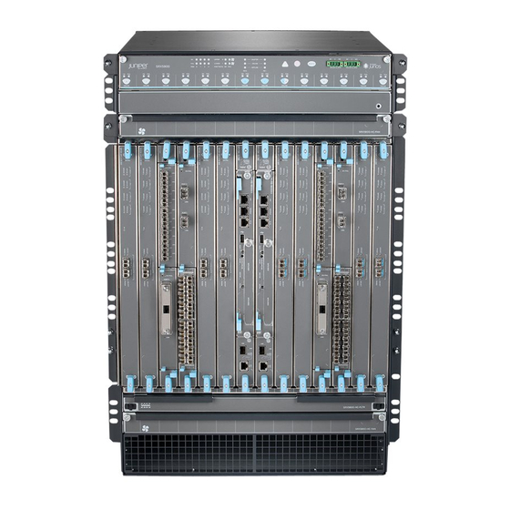
SRX5800 Services Gateway Hardware Guide “SRX5800 Services Gateway Physical Specifications” on page 3 for physical specifications for the SRX5800 Services Gateway. Mounting hardware includes front-mounting flanges on the front of the chassis, and two center-mounting brackets attached to the center of the chassis. - Page 25 Chapter 2: SRX5800 Services Gateway Hardware Components Figure 2: Rear View of a Fully Configured AC-Powered Services Gateway Chassis Copyright © 2014, Juniper Networks, Inc.
-
Page 26: Srx5800 Services Gateway Rack-Mounting Hardware
SRX5800 Services Gateway Hardware Guide Figure 3: Rear View of a Fully Configured DC-Powered Services Gateway Chassis Related Preventing Electrostatic Discharge Damage to the SRX5800 Services Gateway on Documentation page 241 SRX5800 Services Gateway Physical Specifications on page 3 SRX5800 Services Gateway Power System Overview on page 28... -
Page 27: Srx5800 Services Gateway Card Cage And Slots
For an open-frame rack, center-mounting is preferable because of the more even distribution of weight. Related Installing the SRX5800 Services Gateway Mounting Hardware for a Four-Post Rack Documentation or Cabinet on page 63 Installing the SRX5800 Services Gateway Mounting Hardware in an Open-Frame Rack... -
Page 28: Srx5800 Services Gateway Midplane Description
SRX5800 Services Gateway Hardware Guide Table 4: SRX5800 Services Gateway Card Cage Slots (continued) Eligible Cards Card Cage Slot IOC, Flex IOC, or MPC 11 (rightmost) Related SRX5800 Services Gateway Midplane Description on page 12 Documentation SRX5800 Services Gateway Midplane Description... -
Page 29: Srx5800 Services Gateway Interface Card Description
Related SRX5800 Services Gateway Chassis on page 7 Documentation SRX5800 Services Gateway Card Cage and Slots on page 11 SRX5800 Services Gateway Interface Card Description on page 13 SRX5800 Services Gateway SCB Description on page 17 SRX5800 Services Gateway Power System Overview on page 28... - Page 30 SRX5800 Services Gateway Hardware Guide Modular Port Concentrators (MPCs) have slots on the front panel that accept smaller cards called Modular Interface Cards (MICs). Each MIC has one or more physical interface on it. An MPC with MICs installed functions in the same way as a regular I/O card (IOC), but allows greater flexibility in adding different types of Ethernet ports to your services gateway.
- Page 31 SRX5400, SRX5600, and SRX5800 Services Gateway Card Reference www.juniper.net/techpubs/ Related Replacing SRX5800 Services Gateway IOCs on page 168 Documentation Replacing SRX5800 Services Gateway Flex IOCs on page 173 Replacing SRX5800 Services Gateway MPCs on page 181 Copyright © 2014, Juniper Networks, Inc.
-
Page 32: Srx5800 Services Gateway Spc Description
SRX5800 Services Gateway Hardware Guide SRX5800 Services Gateway Card Cage and Slots on page 11 SRX5800 Services Gateway Field-Replaceable Units on page 146 SRX5800 Services Gateway SPC Description Each Services Processing Card (SPC) contains four Services Processing Units (SPUs), which provide the processing power to run integrated services such as firewall, IPsec,... -
Page 33: Srx5800 Services Gateway Host Subsystem Description
The host subsystem has three LEDs that display its status. The host subsystem LEDs are located in the middle of the craft interface. Related SRX5800 Services Gateway Craft Interface Host Subsystem LEDs on page 22 Documentation SRX5800 Services Gateway SCB Description on page 17... - Page 34 (third SCB) card if an SRX5k SPC II (FRU model number: SRX5K-SPC-4-15-320) is installed on the device. If you have installed an SRX5k SPC II on an SRX5800 Services Gateway with a redundant SCB card, make sure to remove the redundant SCB card.
-
Page 35: Srx5800 Services Gateway Routing Engine Description
Related SRX5800 Services Gateway Card Cage and Slots on page 11 Documentation Maintaining the SRX5800 Services Gateway Host Subsystem and SCBs on page 123 Replacing an SRX5800 Services Gateway SCB on page 158 SRX5800 Services Gateway Routing Engine Description The Routing Engine is an Intel-based PC platform that runs Junos OS. Software processes... -
Page 36: Srx5800 Services Gateway Craft Interface
SRX5800 Services Gateway Craft Interface SRX5800 Services Gateway Craft Interface Overview on page 20 SRX5800 Services Gateway Craft Interface Alarm LEDs and Alarm Cutoff/Lamp Test Button on page 21 SRX5800 Services Gateway Craft Interface Host Subsystem LEDs on page 22... - Page 37 SRX5800 Services Gateway Craft Interface Alarm Relay Contacts on page 26 Replacing the SRX5800 Services Gateway Craft Interface on page 148 SRX5800 Services Gateway Craft Interface Alarm LEDs and Alarm Cutoff/Lamp Test Button Two large alarm LEDs are located at the upper right of the craft interface. The circular red LED lights to indicate a critical condition that can result in a system shutdown.
- Page 38 Causes all LEDs on the craft interface to light (for testing) when pressed and held. Related SRX5800 Services Gateway Craft Interface Alarm Relay Contacts on page 26 Documentation SRX5800 Services Gateway Craft Interface Overview on page 20 SRX5800 Services Gateway Craft Interface Host Subsystem LEDs on page 22...
- Page 39 SRX5800 Services Gateway Craft Interface Overview on page 20 Documentation SRX5800 Services Gateway Craft Interface Host Subsystem LEDs on page 22 SRX5800 Services Gateway Craft Interface Card OK/Fail LEDs on page 23 SRX5800 Services Gateway Craft Interface Card OK/Fail LEDs Each slot in the card cage has a pair of LEDs on the craft interface that indicates the status of the card installed in it.
- Page 40 Related SRX5800 Services Gateway Craft Interface Overview on page 20 Documentation SRX5800 Services Gateway Craft Interface Card OK/Fail LEDs on page 23 SRX5800 Services Gateway Craft Interface Online Buttons on page 24 SRX5800 Services Gateway Craft Interface Online Buttons The craft interface has a row of Online/Offline buttons along its lower edge. Each button corresponds to one slot in the card cage.
- Page 41 Chapter 2: SRX5800 Services Gateway Hardware Components user@host> request chassis fpc slot 2 offline node0: -------------------------------------------------------------------------- Offline initiated, use "show chassis fpc" to verify {primary:node0} user@host> show chassis fpc node0: -------------------------------------------------------------------------- Temp CPU Utilization (%) Memory Utilization (%) Slot State...
- Page 42 Documentation SRX5800 Services Gateway Craft Interface Fan LEDs on page 24 SRX5800 Services Gateway Craft Interface Alarm Relay Contacts on page 26 SRX5800 Services Gateway Craft Interface Alarm Relay Contacts The craft interface has two alarm relay contacts for connecting the device to external...
-
Page 43: Srx5800 Services Gateway Power System Description
Connecting an SRX5800 Services Gateway to an External Alarm-Reporting Device on page 90 Alarm Relay Contact Wire Specifications for the SRX5800 Services Gateway on page 298 SRX5800 Services Gateway Power System Description SRX5800 Services Gateway Power System Overview on page 28... -
Page 44: Srx5800 Services Gateway Standard-Capacity Dc Power Supply
SRX5800 Services Gateway Standard-Capacity DC Power Supply LEDs on page 40 SRX5800 Services Gateway Power System Overview The SRX5800 Services Gateway uses either AC or DC power supplies. The services gateway is configurable with two to four AC power supplies or two or four DC power supplies. - Page 45 Figure 14 on page 30 shows the distribution of power from the power supplies to the chassis components in an SRX5800 Services Gateway chassis powered by DC power supplies or high-capacity AC power supplies. Copyright © 2014, Juniper Networks, Inc.
- Page 46 AC power supply in each of the slots PEM0 PEM1 Related Calculating Power Requirements for the SRX5800 Services Gateway on page 275 Documentation SRX5800 Services Gateway Standard-Capacity AC Power Supply on page 34 SRX5800 Services Gateway Standard-Capacity DC Power Supply on page 39...
- Page 47 Chapter 2: SRX5800 Services Gateway Hardware Components Installing an SRX5800 Services Gateway DC Power Supply on page 219 SRX5800 Services Gateway High-Capacity AC Power Supply High-capacity AC power supplies provide a maximum of 4100 W of power each. Two high-capacity power supplies are required, and you can install four high-capacity power supplies for redundancy.
- Page 48 To meet safety and electromagnetic interference (EMI) requirements and to ensure proper operation, the services gateway chassis must be adequately grounded before power is connected. See “Grounding the SRX5800 Services Gateway” on page 96 for instructions. Copyright © 2014, Juniper Networks, Inc.
- Page 49 Chapter 2: SRX5800 Services Gateway Hardware Components Figure 15: High-Capacity AC Power Supply Related Calculating Power Requirements for the SRX5800 Services Gateway on page 275 Documentation SRX5800 Services Gateway High-Capacity AC Power Supply LEDs on page 33 SRX5800 Services Gateway Power System Overview on page 28...
- Page 50 AC-2 OK DC OK LEDs for more information. Related SRX5800 Services Gateway Craft Interface Power Supply LEDs on page 23 Documentation SRX5800 Services Gateway High-Capacity AC Power Supply on page 31 SRX5800 Services Gateway Power System Overview on page 28...
- Page 51 Chapter 2: SRX5800 Services Gateway Hardware Components Figure 16: Standard-Capacity AC Power Supply Related Calculating Power Requirements for the SRX5800 Services Gateway on page 275 Documentation SRX5800 Services Gateway Craft Interface Power Supply LEDs on page 23 SRX5800 Services Gateway Power System Overview on page 28...
- Page 52 AC OK DC OK more information. Related SRX5800 Services Gateway Craft Interface Power Supply LEDs on page 23 Documentation SRX5800 Services Gateway Power System Overview on page 28 SRX5800 Services Gateway Standard-Capacity AC Power Supply on page 34 SRX5800 Services Gateway Standard-Capacity DC Power Supply on page 39 SRX5800 Services Gateway High-Capacity DC Power Supply High-capacity DC power supplies provide a maximum of 4100 W of power each.
- Page 53 Chapter 2: SRX5800 Services Gateway Hardware Components NOTE: The services gateway must be running Junos OS Release 12.1X44-D10 or later in order to use high-capacity DC power supplies. Each high-capacity DC power supply has an input mode switch, covered by a small metal plate.
- Page 54 SRX5800 Services Gateway Hardware Guide Figure 17: High-Capacity DC Power Supply Related Calculating Power Requirements for the SRX5800 Services Gateway on page 275 Documentation SRX5800 Services Gateway Power System Overview on page 28 Installing an SRX5800 Services Gateway DC Power Supply on page 219...
- Page 55 INP1 OK DC OK LEDs for more information. Related SRX5800 Services Gateway Craft Interface Power Supply LEDs on page 23 Documentation SRX5800 Services Gateway Power System Overview on page 28 SRX5800 Services Gateway Standard-Capacity DC Power Supply on page 39...
- Page 56 SRX5800 Services Gateway Hardware Guide Figure 18: Standard-Capacity DC Power Supply Related Calculating Power Requirements for the SRX5800 Services Gateway on page 275 Documentation SRX5800 Services Gateway Power System Overview on page 28 SRX5800 Services Gateway Standard-Capacity DC Power Supply LEDs on page 40...
-
Page 57: Srx5800 Services Gateway Cooling System Description
Amber DC input is present, but connected in reverse polarity. Related SRX5800 Services Gateway Craft Interface Power Supply LEDs on page 23 Documentation SRX5800 Services Gateway Power System Overview on page 28 SRX5800 Services Gateway Standard-Capacity DC Power Supply on page 39... - Page 58 SRX5800 Services Gateway Hardware Guide Figure 19: Airflow Through the Chassis The host subsystem monitors the temperature of the device components. When the device is operating normally, the fans function at lower than full speed. If a fan fails or the ambient temperature rises above a threshold, the speed of the remaining fans is automatically adjusted to keep the temperature within the acceptable range.
-
Page 59: Srx5800 Services Gateway Cable Manager Description
Figure 23: Standard-Capacity Air Filter Tray Figure 24: High-Capacity Air Filter Tray Related Maintaining the Fan Trays on the SRX5800 Services Gateway on page 123 Documentation Maintaining the Air Filter on the SRX5800 Services Gateway on page 122 Troubleshooting the SRX5800 Services Gateway Cooling System on page 138... - Page 60 SRX5800 Services Gateway Hardware Guide Figure 25: Cable Management System Maintenance linkage Release handles Related Replacing the SRX5800 Services Gateway Cable Manager on page 229 Documentation Copyright © 2014, Juniper Networks, Inc.
-
Page 61: Part 2 Setting Up The Srx5800 Services Gateway
Setting Up the SRX5800 Services Gateway SRX5800 Services Gateway Installation on page 47 Preparing the Site for the SRX5800 Services Gateway Installation on page 49 Unpacking the SRX5800 Services Gateway on page 57 Installing the SRX5800 Services Gateway Mounting Hardware on page 63... - Page 62 SRX5800 Services Gateway Hardware Guide Copyright © 2014, Juniper Networks, Inc.
-
Page 63: Srx5800 Services Gateway Installation
Rack on page 65 Remove components from the services gateway chassis as described in “Removing Components from the SRX5800 Chassis Before Installing It in the Rack” on page Lift the services gateway on to the rack as described in “Installing the SRX5800 Services Gateway Chassis in the Rack”... - Page 64 SRX5800 Services Gateway Hardware Guide Connecting the Alarm Relay Wires to the SRX5800 Services Gateway Craft Interface on page 150 Connect the grounding cable as described in “Grounding the SRX5800 Services Gateway” on page WARNING: To meet safety and electromagnetic interference (EMI) requirements and to ensure proper operation, you must properly ground the services gateway chassis before connecting power.
-
Page 65: Preparing The Site For The Srx5800 Services Gateway Installation
CHAPTER 4 Preparing the Site for the SRX5800 Services Gateway Installation Site Preparation Checklist for the SRX5800 Services Gateway on page 49 SRX5800 Services Gateway Rack Requirements on page 50 SRX5800 Services Gateway Cabinet Requirements on page 53 Site Preparation Checklist for the SRX5800 Services Gateway... -
Page 66: Srx5800 Services Gateway Rack Requirements
295,“Calculating Power Margin for Fiber-Optic Cable for the SRX5800 Services Gateway” on page 295 Related Overview of Installing the SRX5800 Services Gateway on page 47 Documentation Unpacking the SRX5800 Services Gateway on page 57 SRX5800 Services Gateway Rack Requirements The services gateway can be installed in a rack. -
Page 67: Srx5800 Services Gateway Rack Size And Strength Requirements
The rack requirements are described in the following topics: SRX5800 Services Gateway Rack Size and Strength Requirements on page 51 Spacing of Rack-Mounting Bracket Holes for the SRX5800 Services Gateway on page 52 Connection to Building Structure for the SRX5800 Services Gateway Rack on page 52... -
Page 68: Rack
Spacing of Rack-Mounting Bracket Holes for the SRX5800 Services Gateway on page 52 Connection to Building Structure for the SRX5800 Services Gateway Rack on page 52 Spacing of Rack-Mounting Bracket Holes for the SRX5800 Services Gateway The services gateway can be mounted in any rack that provides holes or hole patterns spaced at 1 U (1.75 in.) increments. -
Page 69: Srx5800 Services Gateway Cabinet Requirements
Spacing of Rack-Mounting Bracket Holes for the SRX5800 Services Gateway on page 52 Connection to Building Structure for the SRX5800 Services Gateway Rack on page 52 SRX5800 Services Gateway Cabinet Requirements The services gateway can be installed in an enclosed cabinet. The cabinet requirements... - Page 70 Documentation Clearance Requirements for SRX5800 Services Gateway Airflow and Hardware Maintenance on page 52 Site Preparation Checklist for the SRX5800 Services Gateway on page 49 Spacing of Rack-Mounting Bracket Holes for the SRX5800 Services Gateway on page 52 SRX5800 Services Gateway Cabinet Airflow Requirements on page 54...
- Page 71 Chapter 4: Preparing the Site for the SRX5800 Services Gateway Installation Clearance Requirements for SRX5800 Services Gateway Airflow and Hardware Maintenance on page 52 Site Preparation Checklist for the SRX5800 Services Gateway on page 49 Spacing of Rack-Mounting Bracket Holes for the SRX5800 Services Gateway on...
- Page 72 SRX5800 Services Gateway Hardware Guide Copyright © 2014, Juniper Networks, Inc.
-
Page 73: Unpacking The Srx5800 Services Gateway
CHAPTER 5 Unpacking the SRX5800 Services Gateway Tools and Parts Required to Unpack the SRX5800 Services Gateway on page 57 Unpacking the SRX5800 Services Gateway on page 57 Verifying the SRX5800 Services Gateway Parts Received on page 59 Tools and Parts Required to Unpack the SRX5800 Services Gateway... - Page 74 Slide the remainder of the shipping crate cover off the pallet. Remove the foam covering the top of the services gateway. Remove the accessory box and the SRX5800 Services Gateway Getting Started Guide. Verify the parts received as described in “Verifying the SRX5800 Services Gateway...
- Page 75 Installing the SRX5800 Services Gateway Chassis in the Rack on page 76 Site Preparation Checklist for the SRX5800 Services Gateway on page 49 Tools and Parts Required to Unpack the SRX5800 Services Gateway on page 57 Verifying the SRX5800 Services Gateway Parts Received on page 59 Verifying the SRX5800 Services Gateway Parts Received A packing list is included in each shipment.
- Page 76 Ethernet cable, RJ-45/RJ-45, 4-pair stranded UTP, Category 5E, 15' ESD wrist strap with cable Related Overview of Installing the SRX5800 Services Gateway on page 47 Documentation Site Preparation Checklist for the SRX5800 Services Gateway on page 49 Copyright © 2014, Juniper Networks, Inc.
-
Page 77: Tools And Parts Required To Unpack The Srx5800 Services Gateway
Chapter 5: Unpacking the SRX5800 Services Gateway Tools and Parts Required to Unpack the SRX5800 Services Gateway on page 57 Unpacking the SRX5800 Services Gateway on page 57 Copyright © 2014, Juniper Networks, Inc. - Page 78 SRX5800 Services Gateway Hardware Guide Copyright © 2014, Juniper Networks, Inc.
-
Page 79: Installing The Srx5800 Services Gateway Mounting Hardware
CHAPTER 6 Installing the SRX5800 Services Gateway Mounting Hardware Installing the SRX5800 Services Gateway Mounting Hardware for a Four-Post Rack or Cabinet on page 63 Installing the SRX5800 Services Gateway Mounting Hardware in an Open-Frame Rack on page 65 Installing the SRX5800 Services Gateway Mounting Hardware for a Four-Post Rack... - Page 80 Figure 29: Installing the Mounting Hardware for a Four-Post Rack or Cabinet Related Overview of Installing the SRX5800 Services Gateway on page 47 Documentation Site Preparation Checklist for the SRX5800 Services Gateway on page 49 Copyright © 2014, Juniper Networks, Inc.
- Page 81 65 Tools Required to Install the SRX5800 Services Gateway on page 69 Installing the SRX5800 Services Gateway Chassis in the Rack on page 76 Installing the SRX5800 Services Gateway Mounting Hardware in an Open-Frame Rack Before installing the services gateway in an open-frame rack, install the large mounting shelf on the rack.
- Page 82 Installing the SRX5800 Services Gateway Mounting Hardware for a Four-Post Rack or Cabinet on page 63 Tools Required to Install the SRX5800 Services Gateway on page 69 Installing the SRX5800 Services Gateway Chassis in the Rack on page 76 Copyright © 2014, Juniper Networks, Inc.
- Page 83 Chapter 6: Installing the SRX5800 Services Gateway Mounting Hardware Site Preparation Checklist for the SRX5800 Services Gateway on page 49 Copyright © 2014, Juniper Networks, Inc.
- Page 84 SRX5800 Services Gateway Hardware Guide Copyright © 2014, Juniper Networks, Inc.
-
Page 85: Tools Required To Install The Srx5800 Services Gateway
Removing Components from the SRX5800 Chassis Before Installing It in the Rack on page 69 Installing the SRX5800 Services Gateway Chassis in the Rack on page 76 Reinstalling Components in the SRX5800 Services Gateway Chassis After Installing It in the Rack on page 79... -
Page 86: Removing Fan Trays Before Installing The Srx5800 Services Gateway
Removing Fan Trays Before Installing the SRX5800 Services Gateway Chassis on page 72 Removing Cards Before Installing the SRX5800 Services Gateway Chassis on page 74 Removing the Power Supplies Before Installing the SRX5800 Services Gateway Chassis Remove the leftmost power supply first and then work your way to the right. To remove... -
Page 87: Gateway Chassis
Chapter 7: Installing the SRX5800 Services Gateway Figure 31: Removing a Power Supply Before Installing the Services Gateway (Standard-Capacity Power Supply Shown, High-Capacity Similar) Removing the Cable Manager Before Installing the SRX5800 Services Gateway Chassis To remove the cable manager (see Figure 32 on page 72): Attach an ESD grounding strap to your bare wrist, and connect the strap to one of the ESD points on the chassis. - Page 88 SRX5800 Services Gateway Hardware Guide Figure 32: Removing the Cable Manager Removing Fan Trays Before Installing the SRX5800 Services Gateway Chassis To remove the upper or lower fan tray (see Figure 33 on page 73 Figure 34 on page which illustrate the upper and lower fan trays): Attach an ESD grounding strap to your bare wrist, and connect the strap to one of the ESD points on the chassis.
- Page 89 Chapter 7: Installing the SRX5800 Services Gateway Figure 33: Removing an Upper Fan Tray Copyright © 2014, Juniper Networks, Inc.
- Page 90 SRX5800 Services Gateway Hardware Guide Figure 34: Removing a Lower Fan Tray Removing Cards Before Installing the SRX5800 Services Gateway Chassis The services gateway holds up to twelve cards (IOCs, Flex IOCs, MPCs, SCBs, and SPCs), which are installed horizontally in the front of the device. Each card weighs up to 18.3 lb (8.3 kg), be prepared to accept its full weight.
- Page 91 Chapter 7: Installing the SRX5800 Services Gateway CAUTION: Do not leave a fiber-optic transceiver uncovered except when you are inserting or removing cable. The safety cap keeps the port clean and prevents accidental exposure to laser light. CAUTION: Avoid bending fiber-optic cable beyond its minimum bend radius.
-
Page 92: Chassis
Documentation Tools Required to Install the SRX5800 Services Gateway on page 69 Installing the SRX5800 Services Gateway Chassis in the Rack on page 76 Reinstalling Components in the SRX5800 Services Gateway Chassis After Installing It in the Rack on page 79... - Page 93 Chapter 7: Installing the SRX5800 Services Gateway services gateway's weight and is adequately supported at the installation site. To install the services gateway using a lift (see Figure 36 on page 78): Ensure the rack is in its permanent location and is secured to the building. Ensure that the installation site allows adequate clearance for both airflow and maintenance.
- Page 94 Site Preparation Checklist for the SRX5800 Services Gateway on page 49 Tools Required to Install the SRX5800 Services Gateway on page 69 Removing Components from the SRX5800 Chassis Before Installing It in the Rack on page 69 Reinstalling Components in the SRX5800 Services Gateway Chassis After Installing...
-
Page 95: Reinstalling Components In The Srx5800 Services Gateway Chassis After Installing It In The Rack
Chassis on page 79 Reinstalling Fan Trays After Installing the SRX5800 Services Gateway Chassis on page 80 Reinstalling Cards After Installing the SRX5800 Services Gateway Chassis on page 82 Reinstalling the Cable Manager After Installing the SRX5800 Services Gateway Chassis on page 84 Reinstalling Power Supplies After Installing the SRX5800 Services Gateway Chassis Reinstall the rightmost power supply first and then work your way to the left. - Page 96 Figure 37: Reinstalling a Power Supply (Standard-Capacity Shown, High-Capacity Similar) Reinstalling Fan Trays After Installing the SRX5800 Services Gateway Chassis To reinstall the fan trays (see Figure 38 on page 81 Figure 39 on page...
- Page 97 Chapter 7: Installing the SRX5800 Services Gateway Figure 38: Installing an Upper Fan Tray Copyright © 2014, Juniper Networks, Inc.
- Page 98 SRX5800 Services Gateway Hardware Guide Figure 39: Installing a Lower Rear Fan Tray Reinstalling Cards After Installing the SRX5800 Services Gateway Chassis To reinstall cards (IOCs, Flex IOCs, MPCs, SPCs, and SCBs (see Figure 40 on page 84): Attach an ESD grounding strap to your bare wrist, and connect the strap to one of the ESD points on the chassis.
- Page 99 Chapter 7: Installing the SRX5800 Services Gateway handles require that all adjacent components be completely inserted so the ejector handles do not hit them, which could result in damage. The ejector handles have a center of rotation and need to be stored toward the center of the board.
-
Page 100: Gateway Chassis
SRX5800 Services Gateway Hardware Guide Figure 40: Installing an IOC Reinstalling the Cable Manager After Installing the SRX5800 Services Gateway Chassis To reinstall the cable manager (see Figure 41 on page 85): Attach an ESD grounding strap to your bare wrist, and connect the strap to one of the ESD points on the chassis. - Page 101 SRX5800 Services Gateway Chassis on page 7 Documentation Tools Required to Install the SRX5800 Services Gateway on page 69 Removing Components from the SRX5800 Chassis Before Installing It in the Rack on page 69 Installing the SRX5800 Services Gateway Chassis in the Rack on page 76...
- Page 102 SRX5800 Services Gateway Hardware Guide Copyright © 2014, Juniper Networks, Inc.
-
Page 103: Connecting The Srx5800 Services Gateway
CHAPTER 8 Connecting the SRX5800 Services Gateway Tools and Parts Required for SRX5800 Services Gateway Connections on page 87 Connecting the SRX5800 Services Gateway to Management and Alarm Devices on page 88 Connecting Network Cables to SRX5800 Services Gateway IOCs and Port... -
Page 104: Management
Connecting the SRX5800 Services Gateway to Management and Alarm Devices Connecting the SRX5800 Services Gateway to a Network for Out-of-Band Management on page 88 Connecting the SRX5800 Services Gateway to a Management Console or an Auxiliary Device on page 89 Connecting an SRX5800 Services Gateway to an External Alarm-Reporting... - Page 105 Chapter 8: Connecting the SRX5800 Services Gateway Connecting the SRX5800 Services Gateway to a Management Console or an Auxiliary Device To use a system console to configure and manage the Routing Engine, connect it to the appropriate CONSOLE port on the Routing Engine. To use a laptop, modem, or other auxiliary device, connect it to the port on the Routing Engine.
-
Page 106: Connecting Network Cables To Srx5800 Services Gateway Iocs And Port
90 Connecting Network Cables to SRX5800 Services Gateway IOCs and Port Modules on page 91 Console Port Cable and Wire Specifications for the SRX5800 Services Gateway on page 298 RJ-45 Connector Pinouts for the SRX5800 Services Gateway Routing Engine Auxiliary... -
Page 107: Modules
Connecting Network Cables to SRX5800 Services Gateway IOCs and Port Modules on page 91 Alarm Relay Contact Wire Specifications for the SRX5800 Services Gateway on page 298 Connecting Network Cables to SRX5800 Services Gateway IOCs and Port Modules To connect the IOCs, MPCs, and port modules to the network (see... - Page 108 SRX5800 Services Gateway Hardware Guide CAUTION: Do not leave a fiber-optic transceiver uncovered except when inserting or removing cable. The safety cap keeps the port clean and prevents accidental exposure to laser light. Insert the cable connector into the cable connector port on the faceplate.
- Page 109 Related Overview of Installing the SRX5800 Services Gateway on page 47 Documentation Tools and Parts Required for SRX5800 Services Gateway Connections on page 87 Connecting the SRX5800 Services Gateway to a Network for Out-of-Band Management on page 88 Connecting the SRX5800 Services Gateway to a Management Console or an Auxiliary...
- Page 110 SRX5800 Services Gateway Hardware Guide Copyright © 2014, Juniper Networks, Inc.
-
Page 111: Grounding And Providing Power To The Srx5800 Services Gateway
CHAPTER 9 Grounding and Providing Power to the SRX5800 Services Gateway Tools and Parts Required for SRX5800 Services Gateway Grounding and Power Connections on page 95 Grounding the SRX5800 Services Gateway on page 96 Connecting Power to an AC-Powered SRX5800 Services Gateway on page 97... -
Page 112: Grounding The Srx5800 Services Gateway
SRX5800 Services Gateway Hardware Guide Grounding the SRX5800 Services Gateway WARNING: To meet safety and electromagnetic interference (EMI) requirements and to ensure proper operation, you must properly ground the services gateway chassis before connecting power. You ground the services gateway by connecting a grounding cable to earth ground and then attaching it to one of the chassis grounding points using two screws. -
Page 113: Connecting Power To An Ac-Powered Srx5800 Services Gateway
Chapter 9: Grounding and Providing Power to the SRX5800 Services Gateway Figure 49: Connecting the Grounding Cable M6 (Metric) Grounding Point 1/4-20 Grounding Point Dress the grounding cable and verify that it does not touch or block access to services gateway components, and that it does not drape where people could trip on it. - Page 114 SRX5800 Services Gateway Hardware Guide CAUTION: Do not mix AC and DC power supplies within the same services gateway. Damage to the services gateway might occur. You connect AC power to the device by attaching power cords from the AC power sources to the AC appliance inlets located on the chassis above the power supplies.
- Page 115 Chapter 9: Grounding and Providing Power to the SRX5800 Services Gateway Figure 50: Connecting AC Power to the Services Gateway (Standard-Capacity Power Supplies) Copyright © 2014, Juniper Networks, Inc.
- Page 116 SRX5800 Services Gateway Hardware Guide Figure 51: Connecting AC Power to the Services Gateway (High-Capacity Power Supplies) Related AC Power Cord Specifications for the SRX5800 Services Gateway on page 284 Documentation Preventing Electrostatic Discharge Damage to the SRX5800 Services Gateway on page 241...
-
Page 117: Powering On An Ac-Powered Srx5800 Services Gateway
Chapter 9: Grounding and Providing Power to the SRX5800 Services Gateway Powering On an AC-Powered SRX5800 Services Gateway To power on an AC-powered services gateway: Verify that the power supplies are fully inserted in the chassis. Verify that each AC power cord is securely inserted into its appliance inlet. -
Page 118: Connecting Power To A Dc-Powered Srx5800 Services Gateway
Documentation page 241 Overview of Installing the SRX5800 Services Gateway on page 47 Tools and Parts Required for SRX5800 Services Gateway Grounding and Power Connections on page 95 Grounding the SRX5800 Services Gateway on page 96 Connecting Power to an AC-Powered SRX5800 Services Gateway on page 97... - Page 119 Chapter 9: Grounding and Providing Power to the SRX5800 Services Gateway To connect the DC source power cables to the services gateway: Switch off the dedicated customer site circuit breakers. Ensure that the voltage across the DC power source cable leads is 0 V and that there is no chance that the cable leads might become active during installation.
-
Page 120: Powering On An Ac-Powered Srx5800 Services Gateway
Documentation page 241 Overview of Installing the SRX5800 Services Gateway on page 47 Tools and Parts Required for SRX5800 Services Gateway Grounding and Power Connections on page 95 Grounding the SRX5800 Services Gateway on page 96 Powering On a DC-Powered SRX5800 Services Gateway on page 105... -
Page 121: Powering On A Dc-Powered Srx5800 Services Gateway
Chapter 9: Grounding and Providing Power to the SRX5800 Services Gateway Powering Off the SRX5800 Services Gateway on page 106 Powering On a DC-Powered SRX5800 Services Gateway To power on a DC-powered services gateway: Verify that an external management device is connected to one of the Routing Engine... -
Page 122: Powering Off The Srx5800 Services Gateway
Documentation page 241 Overview of Installing the SRX5800 Services Gateway on page 47 Tools and Parts Required for SRX5800 Services Gateway Grounding and Power Connections on page 95 Grounding the SRX5800 Services Gateway on page 96 Connecting Power to a DC-Powered SRX5800 Services Gateway on page 102... - Page 123 Chapter 9: Grounding and Providing Power to the SRX5800 Services Gateway For a DC-powered services gateway, move the DC circuit breaker on each DC power supply faceplate to the off ( ) position. Related Preventing Electrostatic Discharge Damage to the SRX5800 Services Gateway on...
- Page 124 SRX5800 Services Gateway Hardware Guide Copyright © 2014, Juniper Networks, Inc.
-
Page 125: Configuring Junos Os For The Srx5800 Services Gateway
CHAPTER 10 Configuring Junos OS for the SRX5800 Services Gateway SRX5800 Services Gateway Software Configuration Overview on page 109 Initially Configuring the SRX5800 Services Gateway on page 110 Performing Initial Software Configuration Using J-Web on page 113 SRX5800 Services Gateway Software Configuration Overview The services gateway is shipped with the Junos operating system (Junos OS) preinstalled and ready to be configured when the device is powered on. -
Page 126: Initially Configuring The Srx5800 Services Gateway
SRX5800 Services Gateway Hardware Guide Initially Configuring the SRX5800 Services Gateway This procedure connects the device to the network but does not enable it to forward traffic. For complete information about enabling the device to forward traffic, including examples, see the appropriate Junos OS configuration guides. - Page 127 Chapter 10: Configuring Junos OS for the SRX5800 Services Gateway Configure the traffic interface. [edit] admin@# set interfaces ge-6/2/0 unit 0 family inet address address/prefix-length admin@# set interfaces ge-6/3/5 unit 0 family inet address address/prefix-length Configure the default route. [edit] admin@# set routing-options static route 0.0.0.0/0 next-hop gateway...
- Page 128 SRX5800 Services Gateway Hardware Guide interface ge-0/0/0.0; syslog { user * { any emergency; file messages { any any; authorization info; file interactive-commands { interactive-commands any; license { autoupdate { url https://ae1.juniper.net/junos/key_retrieval; interfaces { ge-0/0/0 { unit 0; ge-6/2/0 {...
-
Page 129: Performing Initial Software Configuration Using J-Web
Chapter 10: Configuring Junos OS for the SRX5800 Services Gateway interfaces { ge-6/2/0.0; policies { from-zone trust to-zone untrust { policy bob { match { source-address any; destination-address any; application any; then { permit; Commit the configuration to activate it on the device. -
Page 130: Configuring Interfaces, Zones, And Policies With J-Web
SRX5800 Services Gateway Hardware Guide Configuring Root Authentication and the Management Interface from the CLI Before you can use J-Web to configure your device, you must access the CLI to perform the initial configuration. To configure root authentication and the management interface: Log in as root. -
Page 131: Configuring The Hostname
Chapter 10: Configuring Junos OS for the SRX5800 Services Gateway Enable HTTP on the device to access J-Web. See “Configuring Root Authentication and the Management Interface from the CLI” on page 114 Configure the device with J-Web using the following procedures. - Page 132 SRX5800 Services Gateway Hardware Guide You have successfully configured the physical interface. Repeat these steps to configure the second physical interface for the device. Configuring Zones and Assigning Interfaces To assign interfaces within a trust zone and an untrust zone:...
- Page 133 Chapter 10: Configuring Junos OS for the SRX5800 Services Gateway A message appears after your configuration changes are applied successfully. Click You have successfully configured the security policy. Related Performing Initial Software Configuration on the SRX1400 Services Gateway (CLI Documentation...
- Page 134 SRX5800 Services Gateway Hardware Guide Copyright © 2014, Juniper Networks, Inc.
- Page 135 SRX5800 Services Gateway Hardware Maintenance, Replacement, and Troubleshooting Procedures Maintaining the SRX5800 Services Gateway Hardware Components on page 121 Troubleshooting the SRX5800 Services Gateway Hardware Components on page 135 Replacing SRX5800 Services Gateway Hardware Components on page 145 Copyright © 2014, Juniper Networks, Inc.
- Page 136 SRX5800 Services Gateway Hardware Guide Copyright © 2014, Juniper Networks, Inc.
-
Page 137: Maintaining The Srx5800 Services Gateway Hardware Components
Maintaining the SRX5800 Services Gateway Hardware Components Tools and Parts Required to Maintain the SRX5800 Services Gateway on page 121 Routine Maintenance Procedures for the SRX5800 Services Gateway on page 121 Maintaining the SRX5800 Cooling System Components on page 122... -
Page 138: Maintaining The Srx5800 Cooling System Components
SRX5800 Services Gateway Hardware Guide Related Tools and Parts Required to Maintain the SRX5800 Services Gateway on page 121 Documentation Maintaining the Air Filter on the SRX5800 Services Gateway on page 122 Maintaining the Fan Trays on the SRX5800 Services Gateway on page 123... -
Page 139: Maintaining The Srx5800 Services Gateway Host Subsystem And Scbs
Chapter 11: Maintaining the SRX5800 Services Gateway Hardware Components Maintaining MICs and Port Modules on the SRX5800 Services Gateway on page 127 Maintaining SRX5800 Services Gateway Network Cables on page 128 Maintaining SRX5800 Services Gateway Power Supplies on page 133... - Page 140 SRX5800 Services Gateway Hardware Guide Check the LEDs on the Routing Engine faceplate. To check the status of the Routing Engine, issue the show chassis routing-engine command. The output is similar to the following: user@host> show chassis routing-engine Routing Engine status:...
-
Page 141: Maintaining The Srx5800 Packet Forwarding Engine Components
Chapter 11: Maintaining the SRX5800 Services Gateway Hardware Components Related Tools and Parts Required to Maintain the SRX5800 Services Gateway on page 121 Documentation SRX5800 Services Gateway Craft Interface Host Subsystem LEDs on page 22 Routine Maintenance Procedures for the SRX5800 Services Gateway on page 121... - Page 142 SRX5800 Services Gateway Hardware Guide For more detailed output, add the option. The following example does not specify detail a slot number, which is optional: user@host> show chassis fpc detail Slot 0 information: State Online Temperature 41 degrees C / 105 degrees F...
-
Page 143: Maintaining Mics And Port Modules On The Srx5800 Services Gateway
Maintaining the Fan Trays on the SRX5800 Services Gateway on page 123 Maintaining the SRX5800 Services Gateway Host Subsystem and SCBs on page 123 Maintaining MICs and Port Modules on the SRX5800 Services Gateway on page 127 Maintaining SRX5800 Services Gateway Network Cables on page 128... - Page 144 SRX5800 Services Gateway Hardware Guide Maintaining the Air Filter on the SRX5800 Services Gateway on page 122 Maintaining the Fan Trays on the SRX5800 Services Gateway on page 123 Maintaining the SRX5800 Services Gateway Host Subsystem and SCBs on page 123...
-
Page 145: Handling And Storing Srx5800 Services Gateway Cards
Maintaining the SRX5800 Services Gateway Host Subsystem and SCBs on page 123 Maintaining Interface Cards and SPCs on the SRX5600 Services Gateway on page 125 Maintaining MICs and Port Modules on the SRX5800 Services Gateway on page 127 Maintaining SRX5800 Services Gateway Power Supplies on page 133... - Page 146 This terminology applies to SPCs, IOCs, MPCs, and SCBs in addition to Routing Engines and port modules. Figure 54: Card Edges Related Holding an SRX5800 Services Gateway Card on page 130 Documentation Storing an SRX5800 Services Gateway Card on page 132 Holding an SRX5800 Services Gateway Card When carrying a card, you can hold it either vertically or horizontally.
- Page 147 Chapter 11: Maintaining the SRX5800 Services Gateway Hardware Components Place your other hand at the bottom edge of the card. If the card is horizontal before you grasp it, place your left hand around the faceplate and your right hand along the bottom edge.
- Page 148 Related SRX5800 Services Gateway Card Terminology on page 129 Documentation Storing an SRX5800 Services Gateway Card on page 132 Storing an SRX5800 Services Gateway Card You must store a card as follows: In the services gateway chassis...
-
Page 149: Maintaining Srx5800 Services Gateway Power Supplies
SRX5800 Services Gateway Standard-Capacity AC Power Supply LEDs on page 35 SRX5800 Services Gateway Standard-Capacity DC Power Supply LEDs on page 40 Troubleshooting the SRX5800 Services Gateway with the Junos OS CLI on page 135 Routine Maintenance Procedures for the SRX5800 Services Gateway on page 121 Maintaining SRX5800 Services Gateway Network Cables on page 128 Copyright ©... - Page 150 SRX5800 Services Gateway Hardware Guide Copyright © 2014, Juniper Networks, Inc.
-
Page 151: Troubleshooting Resources For The Srx5800 Services Gateway
Troubleshooting the SRX5800 Services Gateway Power System on page 142 Troubleshooting Resources for the SRX5800 Services Gateway Troubleshooting the SRX5800 Services Gateway with the Junos OS CLI on page 135 Troubleshooting the SRX5800 Services Gateway with Chassis and Interface Alarm... -
Page 152: Alarm Messages
Interface alarms—Indicate a problem with a specific network interface. Related Troubleshooting the SRX5800 Services Gateway with the Junos OS CLI on page 135 Documentation Troubleshooting the SRX5800 Services Gateway with Alarm Relay Contacts on page 136... -
Page 153: Troubleshooting The Srx5800 Services Gateway With The Component
Related SRX5800 Services Gateway Craft Interface Host Subsystem LEDs on page 22 Documentation Troubleshooting the SRX5800 Services Gateway with the Junos OS CLI on page 135 Troubleshooting the SRX5800 Services Gateway with Chassis and Interface Alarm Messages on page 136... -
Page 154: Troubleshooting The Srx5800 Services Gateway Cooling System
Power supply LEDs—Three or four LEDs on each power supply faceplate indicate the status of that power supply. Related Troubleshooting the SRX5800 Services Gateway with the Junos OS CLI on page 135 Documentation Troubleshooting the SRX5800 Services Gateway with Chassis and Interface Alarm... -
Page 155: Troubleshooting Srx5800 Services Gateway Interface Cards
The temperature of the services gateway exceeds the maximum (“temperature hot”) threshold (major alarm and automatic shutdown of the power supplies). Related Troubleshooting the SRX5800 Services Gateway with the Junos OS CLI on page 135 Documentation Troubleshooting the SRX5800 Services Gateway with the Craft Interface LEDs on... -
Page 156: Troubleshooting Srx5800 Services Gateway Mics And Port Modules
For further description of the output from the command, see Junos OS System Basics and Services Command Reference at www.juniper.net/techpubs/ Related Troubleshooting the SRX5800 Services Gateway with the Junos OS CLI on page 135 Documentation Troubleshooting the SRX5800 Services Gateway with the Craft Interface LEDs on page 136... -
Page 157: Troubleshooting Srx5800 Services Gateway Spcs
For further description of the output from the command, see Junos OS System Basics and Services Command Reference at www.juniper.net/techpubs/ Related Troubleshooting the SRX5800 Services Gateway with the Junos OS CLI on page 135 Documentation Troubleshooting the SRX5800 Services Gateway with the Craft Interface LEDs on page 136... -
Page 158: Troubleshooting The Srx5800 Services Gateway Power System
For further description of the output from the command, see Junos OS System Basics and Services Command Reference at www.juniper.net/techpubs/ Related Troubleshooting the SRX5800 Services Gateway with the Junos OS CLI on page 135 Documentation Troubleshooting the SRX5800 Services Gateway with the Craft Interface LEDs on page 136... - Page 159 Chapter 12: Troubleshooting the SRX5800 Services Gateway Hardware Components If an AC power supply is correctly installed and functioning normally, the AC OK LEDs light steadily, and the LED is not lit. DC OK PS FAIL If a DC power supply is correctly installed and functioning normally, the...
- Page 160 SRX5800 Services Gateway Hardware Guide Related Troubleshooting the SRX5800 Services Gateway with the Junos OS CLI on page 135 Documentation Troubleshooting the SRX5800 Services Gateway with the Craft Interface LEDs on page 136 Troubleshooting the SRX5800 Services Gateway with the Component LEDs on page 137...
-
Page 161: Replacing Srx5800 Services Gateway Hardware Components
Replacing an SRX5800 Services Gateway Network Interface Cable on page 193 Replacing SRX5800 Services Gateway SPCs on page 196 Replacing SPCs in an Operating SRX5800 Services Gateway Chassis Cluster on page 203 Replacing SRX5800 Services Gateway XFP and SFP Transceivers on page 206... -
Page 162: Srx5800 Services Gateway Field-Replaceable Units
SCBs SFP and XFP transceivers SPCs MPCs Related Tools and Parts Required to Replace SRX5800 Services Gateway Hardware Documentation Components on page 146 Tools and Parts Required to Replace SRX5800 Services Gateway Hardware Components To replace hardware components, you must have the tools listed in Table 27 on page 146. - Page 163 Chapter 13: Replacing SRX5800 Services Gateway Hardware Components Table 27: Tools and Parts Required (continued) Tool or part Components Blank panels (if component is not reinstalled) Power supply Routing Engine Electrostatic bag or antistatic mat Craft Interface Routing Engine SFP and XFP Transceivers...
-
Page 164: Replacing The Srx5800 Services Gateway Craft Interface
Connecting the Alarm Relay Wires to the SRX5800 Services Gateway Craft Interface on page 150 Disconnecting the Alarm Relay Wires from the SRX5800 Services Gateway Craft Interface To disconnect the alarm relay wires from the services gateway and an alarm-reporting... -
Page 165: Installing The Srx5800 Services Gateway Craft Interface
Chapter 13: Replacing SRX5800 Services Gateway Hardware Components Figure 58: Removing the Craft Interface Installing the SRX5800 Services Gateway Craft Interface To install the craft interface (see Figure 59 on page 149): Attach an ESD grounding strap to your bare wrist, and connect the strap to one of the ESD points on the chassis. -
Page 166: Replacing An Srx5800 Services Gateway Fan Tray
SRX5800 Services Gateway Hardware Guide Connecting the Alarm Relay Wires to the SRX5800 Services Gateway Craft Interface To connect the alarm relay wires between a services gateway and an alarm-reporting device (see Figure 60 on page 150): Prepare the required length of replacement wire with gauge between 28-AWG and 14-AWG (0.08 and 2.08 mm... -
Page 167: Removing An Srx5800 Services Gateway Fan Tray
Place one hand under the fan tray to support it and pull the fan tray completely out of the chassis. Proceed to “Installing an SRX5800 Services Gateway Fan Tray” on page 153 to install the replacement fan tray. Copyright © 2014, Juniper Networks, Inc. - Page 168 SRX5800 Services Gateway Hardware Guide Figure 61: Removing an Upper Fan Tray (Standard-Capacity Shown, High-Capacity Similar) Copyright © 2014, Juniper Networks, Inc.
-
Page 169: Installing An Srx5800 Services Gateway Fan Tray
Chapter 13: Replacing SRX5800 Services Gateway Hardware Components Figure 62: Removing a Lower Fan Tray (Standard-Capacity Shown, High-Capacity Similar) Installing an SRX5800 Services Gateway Fan Tray NOTE: To prevent overheating, install the replacement fan tray immediately after removing the existing fan tray. Do not operate the services gateway for more than two minutes without both fan trays installed. - Page 170 SRX5800 Services Gateway Hardware Guide Figure 63: Installing an Upper Fan Tray (Standard-Capacity Shown, High-Capacity Similar) Copyright © 2014, Juniper Networks, Inc.
-
Page 171: Replacing The Srx5800 Services Gateway Air Filter
Reinstalling Fan Trays After Installing the SRX5800 Services Gateway Chassis on page 80 Maintaining the Fan Trays on the SRX5800 Services Gateway on page 123 Replacing the SRX5800 Services Gateway Air Filter You should change the air filter every six months.To replace the air filter, perform the... -
Page 172: Installing The Srx5800 Services Gateway Air Filter
Lift the air filter out of the air filter tray. Figure 65: Removing the Air Filter (Standard-Capacity Filter Tray Shown, High-Capacity Similar) Installing the SRX5800 Services Gateway Air Filter You should change the air filter every six months. To install the air filter (see... -
Page 173: Replacing Srx5800 Services Gateway Host Subsystem Components
Figure 66: Installing the Air Filter Standard-Capacity Filter Tray Shown, High-Capacity Similar) Related Maintaining the Air Filter on the SRX5800 Services Gateway on page 122 Documentation Replacing SRX5800 Services Gateway Host Subsystem Components Taking the SRX5800 Services Gateway Host Subsystem Offline on page 157... -
Page 174: Replacing An Srx5800 Services Gateway Scb
SRX5800 Services Gateway Hardware Guide Related Operating and Positioning the SRX5800 Services Gateway SCB Ejectors on page 158 Documentation Removing an SRX5800 Services Gateway SCB on page 159 Installing an SRX5800 Services Gateway SCB on page 160 Replacing the SRX5800 Services Gateway Routing Engine on page 162... - Page 175 Chapter 13: Replacing SRX5800 Services Gateway Hardware Components Removing an SRX5800 Services Gateway SCB To remove an SCB (see Figure 67 on page 160): NOTE: The SCB and Routing Engine are removed as a unit. You can also remove the Routing Engine separately.
- Page 176 SRX5800 Services Gateway Hardware Guide Figure 67: Removing an SCB Installing an SRX5800 Services Gateway SCB To install an SCB (see Figure 68 on page 162): Attach an ESD grounding strap to your bare wrist, and connect the strap to one of the ESD points on the chassis.
- Page 177 Chapter 13: Replacing SRX5800 Services Gateway Hardware Components steadily, the SCB is not functioning properly. Contact your customer support representative. To check the status of the SCB: user@host> show chassis environment cb CB 0 status: State Online Master Temperature 30 degrees C / 86 degrees F Power 1 1.2 V...
-
Page 178: Removing The Srx5800 Services Gateway Routing Engine
SRX5800 Services Gateway SCB Description on page 17 Documentation Operating and Positioning the SRX5800 Services Gateway SCB Ejectors on page 158 Maintaining the SRX5800 Services Gateway Host Subsystem and SCBs on page 123 Replacing the SRX5800 Services Gateway Routing Engine... -
Page 179: Removing The Srx5800 Services Gateway Routing Engine
Chapter 13: Replacing SRX5800 Services Gateway Hardware Components Removing the SRX5800 Services Gateway Routing Engine CAUTION: Before you replace a Routing Engine, you must take the host subsystem offline. To remove the Routing Engine (see Figure 69 on page 164): Take the host subsystem offline as described in “Taking the SRX5800 Services... - Page 180 If you have not already done so, take the host subsystem offline. See “Taking the SRX5800 Services Gateway Host Subsystem Offline” on page 157. Attach an ESD grounding strap to your bare wrist, and connect the strap to one of the ESD points on the chassis.
- Page 181 Chapter 13: Replacing SRX5800 Services Gateway Hardware Components Press both of the ejector handles inward to seat the Routing Engine. Tighten the captive screws on the top and bottom of the Routing Engine faceplate. Power on the services gateway. The Routing Engine might require several minutes to boot.
-
Page 182: Replacing The Srx5800 Services Gateway Console Or Auxiliary Cable
SRX5800 Services Gateway Routing Engine Description on page 19 Documentation Taking the SRX5800 Services Gateway Host Subsystem Offline on page 157 Replacing the SRX5800 Services Gateway Console or Auxiliary Cable on page 167 Replacing an SRX5800 Services Gateway SCB on page 158 Copyright © 2014, Juniper Networks, Inc. - Page 183 Replacing the Management Ethernet Cable on an SRX5800 Services Gateway on page 167 Replacing the SRX5800 Services Gateway Console or Auxiliary Cable on page 167 Replacing the Management Ethernet Cable on an SRX5800 Services Gateway One Ethernet cable with RJ-45 connectors is provided with the services gateway. To...
-
Page 184: Replacing Srx5800 Services Gateway Iocs
Preventing Electrostatic Discharge Damage to the SRX5800 Services Gateway on Documentation page 241 Replacing the SRX5800 Services Gateway Routing Engine on page 162 Replacing the Management Ethernet Cable on an SRX5800 Services Gateway on page 167 Replacing SRX5800 Services Gateway IOCs To replace an IOC, perform the following procedures:... - Page 185 Chapter 13: Replacing SRX5800 Services Gateway Hardware Components Label the cables connected to each port on the IOC so that you can later reconnect the cables to the correct ports. Use one of the following methods to take the IOC offline: Press and hold the corresponding IOC online button on the craft interface.
-
Page 186: Installing An Srx5800 Services Gateway Ioc
IOC into a different slot. Figure 74: Removing an IOC Installing an SRX5800 Services Gateway IOC An IOC weighs up to 13.1 lb (5.9 kg). Be prepared to accept its full weight. Copyright © 2014, Juniper Networks, Inc. - Page 187 Chapter 13: Replacing SRX5800 Services Gateway Hardware Components To install an IOC (see Figure 75 on page 172): Attach an electrostatic discharge (ESD) grounding strap to your bare wrist, and connect the strap to one of the ESD points on the chassis.
- Page 188 SRX5800 Services Gateway Hardware Guide For more information about the command, see Junos OS System Basics and Services Command Reference at www.juniper.net/techpubs/ CAUTION: After the LED turns green, wait at least 30 seconds before removing the IOC again, removing an IOC from a different slot, or inserting an IOC in a different slot.
-
Page 189: Replacing Srx5800 Services Gateway Flex Iocs
Chapter 13: Replacing SRX5800 Services Gateway Hardware Components Figure 76: Attaching a Cable to an IOC Fiber-optic cable Related Connecting Network Cables to SRX5800 Services Gateway IOCs and Port Modules Documentation on page 91 Replacing SRX5800 Services Gateway Flex IOCs on page 173... - Page 190 SRX5800 Services Gateway Hardware Guide Use one of the following methods to take the Flex IOC offline: Press and hold the corresponding online button on the craft interface. The green LED next to the button begins to blink. Hold the button down until the LED goes off.
-
Page 191: Installing An Srx5800 Services Gateway Flex Ioc
Chapter 13: Replacing SRX5800 Services Gateway Hardware Components Figure 77: Removing a Flex IOC Installing an SRX5800 Services Gateway Flex IOC NOTE: Your services gateway must be running Junos version 9.5R1 or later in order to recognize Flex IOCs and port modules. - Page 192 Reboot the services gateway. Related Connecting Network Cables to SRX5800 Services Gateway IOCs and Port Modules Documentation on page 91 Replacing SRX5800 Services Gateway IOCs on page 168...
-
Page 193: Replacing Srx5800 Services Gateway Port Modules
Replacing SRX5800 Services Gateway Port Modules To replace a port module, perform the following procedures: Removing an SRX5800 Services Gateway Port Module on page 177 Installing an SRX5800 Services Gateway Port Module on page 179 Removing an SRX5800 Services Gateway Port Module Port modules are installed in Flex IOCs in the services gateway card cage. - Page 194 SRX5800 Services Gateway Hardware Guide CAUTION: Avoid bending fiber-optic cable beyond its minimum bend radius. An arc smaller than a few inches in diameter can damage the cable and cause problems that are difficult to diagnose. Loosen the captive screws that retain the port module in its slot in the Flex IOC.
-
Page 195: Installing An Srx5800 Services Gateway Port Module
Chapter 13: Replacing SRX5800 Services Gateway Hardware Components Installing an SRX5800 Services Gateway Port Module To install a port module into a Flex IOC (see Figure 80 on page 179): Attach an electrostatic discharge (ESD) grounding strap to your bare wrist, and connect the strap to one of the ESD points on the chassis. - Page 196 Connecting Network Cables to SRX5800 Services Gateway IOCs and Port Modules Documentation on page 91 Maintaining MICs and Port Modules on the SRX5800 Services Gateway on page 127 Troubleshooting SRX5800 Services Gateway MICs and Port Modules on page 140 Copyright © 2014, Juniper Networks, Inc.
-
Page 197: Replacing Srx5800 Services Gateway Mpcs
Chapter 13: Replacing SRX5800 Services Gateway Hardware Components Replacing SRX5800 Services Gateway MPCs To replace an MPC, perform the following procedures: Removing an SRX5800 Services Gateway MPC on page 181 Installing an SRX5800 Services Gateway MPC on page 183 Removing an SRX5800 Services Gateway MPC An MPC installs vertically in the front of the services gateway. - Page 198 SRX5800 Services Gateway Hardware Guide Grasp the handles, and slide the MPC straight out of the card cage halfway. See Figure 81 on page 182. Figure 81: Removing an MPC Place one hand around the front of the MPC (the MIC housing) and the other hand under it to support it.
-
Page 199: Installing An Srx5800 Services Gateway Mpc
Chapter 13: Replacing SRX5800 Services Gateway Hardware Components After you remove each MIC, immediately place it on an antistatic mat or in an electrostatic bag. If you are not reinstalling an MPC into the emptied line card slots within a short time, install a blank DPC panel over each slot to maintain proper airflow in the card cage. - Page 200 SRX5800 Services Gateway Hardware Guide Figure 82: Installing an MPC Slide the MPC all the way into the card cage until you feel resistance. Grasp both ejector handles, and rotate them clockwise simultaneously until the MPC is fully seated. If any of the MICs on the MPC connect to fiber-optic cable, remove the rubber safety cap from each transceiver and cable.
-
Page 201: Replacing Srx5800 Services Gateway Mics
Related Replacing SRX5800 Services Gateway MICs on page 185 Documentation Installing MPCs and MICs in an Operating SRX5800 Services Gateway Chassis Cluster on page 190 Troubleshooting SRX5800 Services Gateway Interface Cards on page 139 Replacing SRX5800 Services Gateway MICs... - Page 202 SRX5800 Services Gateway Hardware Guide WARNING: Do not look directly into a fiber-optic transceiver or into the ends of fiber-optic cables. Fiber-optic transceivers and fiber-optic cable connected to a transceiver emit laser light that can damage your eyes. CAUTION: Do not leave a fiber-optic transceiver uncovered except when you are inserting or removing cable.
- Page 203 Chapter 13: Replacing SRX5800 Services Gateway Hardware Components Figure 83: Removing a MIC Grasp the handles on the MIC faceplate, and slide the MIC out of the MPC card carrier. Place it in the electrostatic bag or on the antistatic mat.
-
Page 204: Installing An Srx5800 Services Gateway Mic
MICs in the services gateways in the cluster without incurring downtime on your network. See “Installing MPCs and MICs in an Operating SRX5800 Services Gateway Chassis Cluster” on page 190 for more information. To install a MIC: Attach an electrostatic discharge (ESD) grounding strap to your bare wrist, and connect the strap to one of the ESD points on the chassis. - Page 205 Chapter 13: Replacing SRX5800 Services Gateway Hardware Components Figure 84: Installing a MIC Align the rear of the MIC with the guides located at the corners of the MIC slot. Slide the MIC into the MPC until it is firmly seated in the MPC. The ejector knob will automatically move in towards the faceplate to lock the MIC in position as it seats.
-
Page 206: Cluster
Related Replacing SRX5800 Services Gateway MPCs on page 181 Documentation Installing MPCs and MICs in an Operating SRX5800 Services Gateway Chassis Cluster on page 190 Troubleshooting SRX5800 Services Gateway Interface Cards on page 139 Installing MPCs and MICs in an Operating SRX5800 Services Gateway Chassis Cluster If your services gateway is part of a chassis cluster, you can install MPCs in the services gateways in the cluster without incurring downtime on your network. - Page 207 If that remaining device fails for any reason, you incur network downtime until you restart at least one of the devices. To install MPCs in an operating SRX5800 Services Gateway cluster without incurring downtime: Use the console port on the Routing Engine to establish a CLI session with one of the devices in the cluster.
- Page 208 Wait for the secondary services gateway to completely shut down. Install the new MPCs in the powered-off services gateway using the procedure in “Installing an SRX5800 Services Gateway MPC” on page 183. Install MICs in the MPCs in the powered-off services gateway using the procedure in “Installing an SRX5800 Services Gateway MIC”...
-
Page 209: Replacing An Srx5800 Services Gateway Network Interface Cable
To replace a network interface cable connected to an IOC, port module, or MIC, perform the following procedures: Removing an SRX5800 Services Gateway Network Interface Cable on page 193 Installing an SRX5800 Services Gateway Network Interface Cable on page 194... -
Page 210: Installing An Srx5800 Services Gateway Network Interface Cable
Remove the cable from the cable manager and detach it from the destination port. Installing an SRX5800 Services Gateway Network Interface Cable To install a fiber-optic cable on a network interface on an IOC, port module, or MIC: Have ready a length of the type of cable used by the component. - Page 211 Chapter 13: Replacing SRX5800 Services Gateway Hardware Components CAUTION: Do not leave a fiber-optic transceiver uncovered except when you are inserting or removing cable. The safety cap keeps the port clean and prevents accidental exposure to laser light. Insert the cable connector into the cable connector port on the component faceplate.
-
Page 212: Replacing Srx5800 Services Gateway Spcs
PIC functioning by issuing the command. show chassis fpc pic-status Related Connecting Network Cables to SRX5800 Services Gateway IOCs and Port Modules Documentation on page 91 Replacing SRX5800 Services Gateway SPCs To replace an SPC, perform the following procedures:... - Page 213 Chapter 13: Replacing SRX5800 Services Gateway Hardware Components CAUTION: Avoid bending fiber-optic cable beyond its minimum bend radius. An arc smaller than a few inches in diameter can damage the cable and cause problems that are difficult to diagnose. CAUTION: Do not let fiber-optic cable hang free from the connector.
-
Page 214: Installing An Srx5800 Services Gateway Spc
SRX5800 Services Gateway Hardware Guide Figure 85: Removing an SPC Installing an SRX5800 Services Gateway SPC To install an SPC (see Figure 86 on page 200): Attach an ESD grounding strap to your bare wrist, and connect the strap to one of the ESD points on the chassis. - Page 215 Chapter 13: Replacing SRX5800 Services Gateway Hardware Components If the SPC uses fiber-optic cable, remove the rubber safety cap from each transceiver and cable. WARNING: Do not look directly into a fiber-optic transceiver or into the ends of fiber-optic cables. Fiber-optic transceivers and fiber-optic cable connected to a transceiver emit laser light that can damage your eyes.
- Page 216 SRX5800 Services Gateway Hardware Guide Figure 86: Installing an SPC Copyright © 2014, Juniper Networks, Inc.
- Page 217 Chapter 13: Replacing SRX5800 Services Gateway Hardware Components Figure 87: Attaching a Cable to an SPC Fiber-optic cable Copyright © 2014, Juniper Networks, Inc.
- Page 218 Maintaining Interface Cards and SPCs on the SRX5600 Services Gateway on page 125 Documentation Troubleshooting SRX5800 Services Gateway SPCs on page 141 Replacing SPCs in an Operating SRX5800 Services Gateway Chassis Cluster on page 203 Copyright © 2014, Juniper Networks, Inc.
-
Page 219: Replacing Spcs In An Operating Srx5800 Services Gateway Chassis Cluster
Chapter 13: Replacing SRX5800 Services Gateway Hardware Components Replacing SPCs in an Operating SRX5800 Services Gateway Chassis Cluster If your SRX5800 Services Gateway is part of an operating chassis cluster, you can replace SPCs without incurring downtime on your network. You can also replace first-generation SPCs with next-generation SRX5K-SPC-4-15-320 SPCs. - Page 220 Wait for the secondary services gateway to completely shut down. If you are replacing first-generation SPCs with SRX5K-SPC-4-15-320 SPCs, use the procedure in “Removing an SRX5800 Services Gateway SPC” on page 196 to remove the SPCs you are replacing from the powered-off services gateway.
- Page 221 Use the show chassis cluster status command to make sure that the priority for all redundancy groups is greater than zero. Related Installing an SRX5800 Services Gateway SPC on page 198 Documentation Copyright © 2014, Juniper Networks, Inc.
-
Page 222: Replacing Srx5800 Services Gateway Xfp And Sfp Transceivers
Replacing SRX5800 Services Gateway XFP and SFP Transceivers To replace an XFP or SFP transceiver, perform the following procedures: Removing an SRX5800 Services Gateway SFP or XFP Transceiver on page 206 Installing an SRX5800 Services Gateway SFP or XFP Transceiver on page 207 Removing an SRX5800 Services Gateway SFP or XFP Transceiver Transceivers are installed in a MIC or SPC. -
Page 223: Installing An Srx5800 Services Gateway Sfp Or Xfp Transceiver
After removing a transceiver from the card, wait at least 30 seconds before reinserting it or inserting a transceiver into a different socket. Installing an SRX5800 Services Gateway SFP or XFP Transceiver Transceivers that are installed in an MIC or SPC. Transceivers are hot-insertable and hot-removable. -
Page 224: Upgrading An Srx5800 Services Gateway From Standard-Capacity To High-Capacity Power Supplies
Upgrading an SRX5800 Services Gateway from Standard-Capacity to High-Capacity Power Supplies You can replace the standard-capacity power supplies in the SRX5800 Services Gateway with either two or four high-capacity power supplies of the same input type (AC or DC). Two high-capacity power supplies provide adequate power for a fully loaded chassis;... - Page 225 Install a high-capacity AC power supply in the vacant slot in the back of the chassis. “Installing an SRX5800 Services Gateway AC Power Supply” on page 214 instructions on installing AC power supplies.
- Page 226 AC power supplies in the slots you vacated in Step 11. See “Installing an SRX5800 Services Gateway AC Power Supply” on page 214 instructions on installing AC power supplies. Check the LEDs on all installed high-capacity AC power supply faceplates to ensure that they are operating properly.
-
Page 227: Replacing An Srx5800 Services Gateway Ac Power Supply
Chapter 13: Replacing SRX5800 Services Gateway Hardware Components Install a high-capacity DC power supply in the slot in the back of the chassis. PEM0 “Installing an SRX5800 Services Gateway DC Power Supply” on page 219 instructions on installing DC power supplies. Repeat Step and Step... - Page 228 SRX5800 Services Gateway Hardware Guide NOTE: After powering off a power supply, wait at least 60 seconds before turning it back on. To remove an AC power supply (see Figure 89 on page 213): Switch off the dedicated customer site circuit breaker for the power supply, and remove the power cord from the AC power source.
- Page 229 Chapter 13: Replacing SRX5800 Services Gateway Hardware Components Figure 89: Removing an AC Power Supply (Standard-Capacity Shown, High-Capacity Similar) WARNING: Do not touch the power connector on the top of the power supply (see Figure 90 on page 213). It can contain dangerous voltages.
-
Page 230: Installing An Srx5800 Services Gateway Ac Power Supply
SRX5800 Services Gateway Hardware Guide Installing an SRX5800 Services Gateway AC Power Supply To install an AC power supply (see Figure 92 on page 215): Attach an ESD grounding strap to your bare wrist, and connect the strap to one of the ESD points on the chassis. - Page 231 If you are installing a high-capacity power supply, connect a power cord to the appliance inlet at the top edge of the power supply. For more information, see “Connecting an SRX5800 Services Gateway AC Power Supply Cord” on page 224.
-
Page 232: Replacing An Srx5800 Services Gateway Dc Power Supply
SRX5800 Services Gateway Standard-Capacity AC Power Supply LEDs on page 35 SRX5800 Services Gateway AC Power Supply Specifications on page 282 Replacing an SRX5800 Services Gateway AC Power Supply Cord on page 224 Replacing an SRX5800 Services Gateway DC Power Supply... - Page 233 Chapter 13: Replacing SRX5800 Services Gateway Hardware Components WARNING: Before performing DC power procedures, ensure that power is removed from the DC circuit. To ensure that all power is off, locate the circuit breaker on the panel board that services the DC circuit, switch the circuit breaker to the off position, and tape the switch handle of the circuit breaker in the off position.
- Page 234 SRX5800 Services Gateway Hardware Guide Let go of the locking pin in the release lever. Ensure that the pin is seated inside the corresponding hole in the chassis. Pull the power supply straight out of the chassis. The power supply can weigh up to 12 lb (5.5 kg).
-
Page 235: Installing An Srx5800 Services Gateway Dc Power Supply
Chapter 13: Replacing SRX5800 Services Gateway Hardware Components Figure 94: Top of the Power Supply Showing Midplane Connector Connector end of AC or DC power supply Installing an SRX5800 Services Gateway DC Power Supply WARNING: Before performing DC power procedures, ensure that power is removed from the DC circuit. - Page 236 SRX5800 Services Gateway Hardware Guide If necessary, pull the spring-loaded locking pin in the release lever away from the chassis and turn the release lever counterclockwise until it stops. Let go of the locking pin in the release lever. Ensure that the pin is seated inside the corresponding hole in the chassis.
- Page 237 Chapter 13: Replacing SRX5800 Services Gateway Hardware Components Let go of the locking pin in the release lever. Ensure that the pin is seated inside the corresponding hole in the chassis. Remove the clear plastic cover protecting the terminal studs on the faceplate.
- Page 238 SRX5800 Services Gateway Hardware Guide Apply between 23 lb-in. (2.6 Nm) and 25 lb-in. (2.8 Nm) of torque to each nut (see Figure 96 on page 221). For a high-capacity power supply: INP0 , attach the positive (+) DC source power cable lug to the (return) terminal.
- Page 239 LED is lit, and that the DC OK PS FAIL LED is not lit. Related SRX5800 Services Gateway High-Capacity DC Power Supply on page 36 Documentation SRX5800 Services Gateway High-Capacity DC Power Supply LEDs on page 38 Copyright © 2014, Juniper Networks, Inc.
-
Page 240: Replacing An Srx5800 Services Gateway Ac Power Supply Cord
SRX5800 Services Gateway DC Power Supply Specifications on page 286 Replacing an SRX5800 Services Gateway AC Power Supply Cord To replace an SRX5800 Services Gateway AC power supply cord, perform the following procedures: Disconnecting an SRX5800 Services Gateway AC Power Supply Cord on page 224... - Page 241 Chapter 13: Replacing SRX5800 Services Gateway Hardware Components Verify that the AC input switch nearest to the appliance inlet for the power cord you are replacing is in the off ( ) position: For standard-capacity AC power supplies, there is only one AC input switch for each power supply;...
-
Page 242: Replacing An Srx5800 Services Gateway Dc Power Supply Cable
Replacing an SRX5800 Services Gateway AC Power Supply on page 211 Replacing an SRX5800 Services Gateway DC Power Supply Cable To replace an SRX5800 Services Gateway DC power supply cable, perform the following procedures: Disconnecting an SRX5800 Services Gateway DC Power Supply Cable on page 226... -
Page 243: Connecting An Srx5800 Services Gateway Dc Power Supply Cable
For a standard-capacity power supply, loosen the captive screw on the cable restraint on the lower edge of the power supply faceplate. Carefully move the power cable out of the way. Connecting an SRX5800 Services Gateway DC Power Supply Cable WARNING: Before performing DC power procedures, ensure that power is removed from the DC circuit. - Page 244 SRX5800 Services Gateway Hardware Guide Figure 98: Connecting Power Cables to a Standard Capacity DC Power Supply Figure 99: Connecting DC Power Cables to a High-Capacity DC Power Supply Terminal studs Cable Split washer Copyright © 2014, Juniper Networks, Inc.
-
Page 245: Replacing The Srx5800 Services Gateway Cable Manager
SRX5800 Services Gateway High-Capacity DC Power Supply on page 36 Documentation SRX5800 Services Gateway High-Capacity DC Power Supply LEDs on page 38 SRX5800 Services Gateway Standard-Capacity DC Power Supply on page 39 SRX5800 Services Gateway Standard-Capacity DC Power Supply LEDs on page 40... -
Page 246: Removing The Srx5800 Services Gateway Cable Manager
SRX5800 Services Gateway Hardware Guide Removing the SRX5800 Services Gateway Cable Manager To remove the cable manager (see Figure 100 on page 230): Attach an ESD grounding strap to your bare wrist, and connect the strap to one of the ESD points on the chassis. - Page 247 Figure 101: Installing the Cable Manager Related SRX5800 Services Gateway Cable Manager Description on page 43 Documentation Removing the Cable Manager Before Installing the SRX5800 Services Gateway Chassis on page 71 Reinstalling the Cable Manager After Installing the SRX5800 Services Gateway Chassis on page 84...
- Page 248 SRX5800 Services Gateway Hardware Guide Copyright © 2014, Juniper Networks, Inc.
-
Page 249: Appendixes
SRX5800 Services Gateway Environmental Specifications on page 273 SRX5800 Services Gateway Power Guidelines, Requirements, and Specifications on page 275 Cable and Wire Guidelines and Specifications for the SRX5800 Services Gateway on page 293 Cable Connector Pinouts on page 299 Contacting Customer Support and Returning the SRX5800 Services Gateway Hardware on page 301 Copyright ©... - Page 250 SRX5800 Services Gateway Hardware Guide Copyright © 2014, Juniper Networks, Inc.
- Page 251 Equipment on page 243 SRX5800 Services Gateway Installation Safety Guidelines and Warnings on page 244 SRX5800 Services Gateway Laser and LED Safety Guidelines and Warnings on page 250 SRX5800 Services Gateway Maintenance and Operational Safety Guidelines and Warnings on page 254...
- Page 252 SRX5800 Services Gateway Hardware Guide WARNING: This symbol means danger. You are in a situation that could cause bodily injury. Before you work on any equipment, be aware of the hazards involved with electrical circuitry and be familiar with standard practices for preventing accidents.
-
Page 253: Appendix A Safety And Regulatory Compliance Information
Related SRX5800 Services Gateway General Safety Guidelines and Warnings on page 237 Documentation Preventing Electrostatic Discharge Damage to the SRX5800 Services Gateway on... -
Page 254: Additional Srx5800 Services Gateway Warnings
Avoid touching uninsulated electrical wires or terminals that have not been disconnected from their power source. Such an action could cause electrical shock. Related SRX5800 Services Gateway Definition of Safety Warning Levels on page 235 Documentation Preventing Electrostatic Discharge Damage to the SRX5800 Services Gateway on... -
Page 255: Restricted Access Area Warning
Restricted Access Area Warning on page 239 Documentation SRX5800 Services Gateway General Safety Guidelines and Warnings on page 237 SRX5800 Services Gateway Definition of Safety Warning Levels on page 235 Preventing Electrostatic Discharge Damage to the SRX5800 Services Gateway on... -
Page 256: Preventing Electrostatic Discharge Damage To The Srx5800 Services
Related Qualified Personnel Warning on page 238 Documentation SRX5800 Services Gateway General Safety Guidelines and Warnings on page 237 SRX5800 Services Gateway Definition of Safety Warning Levels on page 235 Preventing Electrostatic Discharge Damage to the SRX5800 Services Gateway on... - Page 257 Appendix A: Safety and Regulatory Compliance Information Preventing Electrostatic Discharge Damage to the SRX5800 Services Gateway Many services gateway hardware components are sensitive to damage from static electricity. Some components can be impaired by voltages as low as 30 V. You can easily generate potentially damaging static voltages whenever you handle plastic or foam packing material or if you move components across plastic or carpets.
- Page 258 SRX5800 Services Gateway Hardware Guide Figure 103: ESD Point on Rear of Services Gateway Avoid contact between the component and your clothing. ESD voltages emitted from clothing can still damage components. When removing or installing a component, always place it component-side up on an...
-
Page 259: Equipment
Documentation Restricted Access Area Warning on page 239 SRX5800 Services Gateway General Safety Guidelines and Warnings on page 237 SRX5800 Services Gateway Definition of Safety Warning Levels on page 235 SRX5800 Services Gateway Fire Safety Requirements and Fire Suppression Equipment... -
Page 260: Ramp Warning
To keep warranties effective, do not use a dry chemical fire extinguisher to control a fire at or near a Juniper Networks services gateway. If a dry chemical fire extinguisher is used, the unit is no longer eligible for coverage under a service agreement. - Page 261 Keep your knees bent and your back relatively straight and avoid twisting your body as you lift. Balance the load evenly and be sure that your footing is solid. Related SRX5800 Services Gateway General Safety Guidelines and Warnings on page 237 Documentation Installation Instructions Warning on page 245...
- Page 262 De onderstaande richtlijnen worden verstrekt om uw veiligheid te verzekeren: De Juniper Networks services gateway moet in een stellage worden geïnstalleerd die aan een bouwsel is verankerd. Dit toestel dient onderaan in het rek gemonteerd te worden als het toestel het enige in het rek is.
- Page 263 Les directives ci-dessous sont destinées à assurer la protection du personnel: Le rack sur lequel est monté le Juniper Networks services gateway doit être fixé à la structure du bâtiment. Si cette unité constitue la seule unité montée en casier, elle doit être placée dans le bas.
- Page 264 Vær nøye med at systemet er stabilt. Følgende retningslinjer er gitt for å verne om sikkerheten: Juniper Networks services gateway må installeres i et stativ som er forankret til bygningsstrukturen. Denne enheten bør monteres nederst i kabinettet hvis dette er den eneste enheten i kabinettet.
- Page 265 Related Chassis Lifting Guidelines on page 244 Documentation SRX5800 Services Gateway General Safety Guidelines and Warnings on page 237 Installation Instructions Warning on page 245 Ramp Warning on page 249 Ramp Warning WARNING: When installing the services gateway, do not use a ramp inclined at more than 10 degrees.
-
Page 266: Srx5800 Services Gateway Laser And Led Safety Guidelines And Warnings
Related Chassis Lifting Guidelines on page 244 Documentation SRX5800 Services Gateway General Safety Guidelines and Warnings on page 237 Installation Instructions Warning on page 245 Rack-Mounting Requirements and Warnings on page 246 SRX5800 Services Gateway Laser and LED Safety Guidelines and Warnings... -
Page 267: Class 1 Laser Warning
Warnung Class 1 LED-Produktwarnung. Avvertenza Avvertenza prodotto LED di Classe 1. Advarsel LED-produkt i klasse 1. Aviso Produto de classe 1 com LED. ¡Atención! Aviso sobre producto LED de Clase 1. Varning! Lysdiodprodukt av klass 1. Copyright © 2014, Juniper Networks, Inc. -
Page 268: Laser Beam Warning
SRX5800 Services Gateway Hardware Guide Related General Laser Safety Guidelines on page 250 Documentation Class 1 Laser Warning on page 251 Laser Beam Warning on page 252 Radiation from Open Port Apertures Warning on page 253 Laser Beam Warning WARNING: Do not stare into the laser beam or view it directly with optical instruments. -
Page 269: Radiation From Open Port Apertures Warning
öppningar. Related General Laser Safety Guidelines on page 250 Documentation Class 1 Laser Warning on page 251 Class 1 LED Product Warning on page 251 Laser Beam Warning on page 252 Copyright © 2014, Juniper Networks, Inc. -
Page 270: Battery Handling Warning
SRX5800 Services Gateway Hardware Guide SRX5800 Services Gateway Maintenance and Operational Safety Guidelines and Warnings Battery Handling Warning on page 254 Jewelry Removal Warning on page 255 Lightning Activity Warning on page 256 Operating Temperature Warning on page 257 Product Disposal Warning on page 258... - Page 271 Metallgegenstände erhitzen sich, wenn sie an das Netz und die Erde angeschlossen werden, und können schwere Verbrennungen verursachen oder an die Anschlußklemmen angeschweißt werden. Avvertenza Prima di intervenire su apparecchiature collegate alle linee di alimentazione, togliersi qualsiasi monile (inclusi anelli, collane, braccialetti Copyright © 2014, Juniper Networks, Inc.
- Page 272 SRX5800 Services Gateway Hardware Guide ed orologi). Gli oggetti metallici si riscaldano quando sono collegati tra punti di alimentazione e massa: possono causare ustioni gravi oppure il metallo può saldarsi ai terminali. Advarsel Fjern alle smykker (inkludert ringer, halskjeder og klokker) før du skal arbeide på...
- Page 273 104°F (40°C). To prevent airflow restriction, allow at least 6 in. (15.2 cm) of clearance around the ventilation openings. Waarschuwing Om te voorkomen dat welke services gateway van de Juniper Networks services gateway dan ook oververhit raakt, dient u deze niet te bedienen op een plaats waar de maximale aanbevolen omgevingstemperatuur van 40°C wordt overschreden.
- Page 274 15,2 cm à volta das aberturas de ventilação. ¡Atención! Para impedir que un encaminador de la serie Juniper Networks services gateway se recaliente, no lo haga funcionar en un área en la que se supere la temperatura ambiente máxima recomendada de 40°C.
-
Page 275: In Case Of Electrical Accident
Jewelry Removal Warning on page 255 Lightning Activity Warning on page 256 Operating Temperature Warning on page 257 SRX5800 Services Gateway Electrical Safety Guidelines and Warnings In Case of Electrical Accident on page 259 General Electrical Safety Guidelines and Warnings on page 260... -
Page 276: General Electrical Safety Guidelines And Warnings
General Electrical Safety Guidelines and Warnings on page 260 Documentation DC Power Electrical Safety Guidelines and Warnings on page 264 SRX5800 Services Gateway Agency Approvals on page 270 General Electrical Safety Guidelines and Warnings Install the services gateway in compliance with the following local, national, or international electrical codes: United States—National Fire Protection Association (NFPA 70), United States... - Page 277 Varoitus Tässä laitteessa on useampia virtalähdekytkentöjä. Kaikki kytkennät on irrotettava kokonaan, jotta virta poistettaisiin täysin laitteesta. Attention Cette unité est équipée de plusieurs raccordements d'alimentation. Pour supprimer tout courant électrique de l'unité, tous les cordons d'alimentation doivent être débranchés. Copyright © 2014, Juniper Networks, Inc.
- Page 278 SRX5800 Services Gateway Hardware Guide Warnung Diese Einheit verfügt über mehr als einen Stromanschluß; um Strom gänzlich von der Einheit fernzuhalten, müssen alle Stromzufuhren abgetrennt sein. Avvertenza Questa unità ha più di una connessione per alimentatore elettrico; tutte le connessioni devono essere completamente rimosse per togliere l'elettricità...
- Page 279 Aviso O dispositivo foi criado para operar com sistemas de corrente TN. ¡Atención! El equipo está diseñado para trabajar con sistemas de alimentación tipo TN. Varning! Enheten är konstruerad för användning tillsammans med elkraftssystem av TN-typ. Copyright © 2014, Juniper Networks, Inc.
-
Page 280: Dc Power Electrical Safety Guidelines And Warnings
In Case of Electrical Accident on page 259 Documentation DC Power Electrical Safety Guidelines and Warnings on page 264 SRX5800 Services Gateway Agency Approvals on page 270 DC Power Electrical Safety Guidelines and Warnings When working with DC-powered equipment, observe the following guidelines and... - Page 281 Waarschuwing Voordat u een van de onderstaande procedures uitvoert, dient u te controleren of de stroom naar het gelijkstroom circuit uitgeschakeld Copyright © 2014, Juniper Networks, Inc.
- Page 282 SRX5800 Services Gateway Hardware Guide is. Om u ervan te verzekeren dat alle stroom UIT is geschakeld, kiest u op het schakelbord de stroomverbreker die het gelijkstroom circuit bedient, draait de stroomverbreker naar de UIT positie en plakt de schakelaarhendel van de stroomverbreker met plakband in de UIT positie vast.
- Page 283 Wire the DC power supply using the appropriate lugs. When connecting power, the proper wiring sequence is ground to ground, +RTN to +RTN, then –48 V to –48 V. When disconnecting power, the proper wiring Copyright © 2014, Juniper Networks, Inc.
- Page 284 SRX5800 Services Gateway Hardware Guide sequence is –48 V to –48 V, +RTN to +RTN, then ground to ground. Note that the ground wire should always be connected first and disconnected last. Waarschuwing De juiste bedradingsvolgorde verbonden is aarde naar aarde, +RTN naar +RTN, en –48 V naar –...
- Page 285 Advarsel Hvis det er nødvendig med flertrådede ledninger, brukes godkjente ledningsavslutninger, som for eksempel lukket sløyfe eller spadetype med oppoverbøyde kabelsko. Disse avslutningene skal ha riktig størrelse i forhold til ledningene, og skal klemme sammen både isolasjonen og lederen. Copyright © 2014, Juniper Networks, Inc.
-
Page 286: Srx5800 Services Gateway Agency Approvals
General Electrical Safety Guidelines and Warnings on page 260 SRX5800 Services Gateway Agency Approvals on page 270 SRX5800 Services Gateway DC Power Supply Specifications on page 286 SRX5800 Services Gateway Chassis Grounding Point Specifications on page 280 SRX5800 Services Gateway Agency Approvals... -
Page 287: Canada
Documentation General Electrical Safety Guidelines and Warnings on page 260 DC Power Electrical Safety Guidelines and Warnings on page 264 SRX5800 Services Gateway Compliance Statements for EMC Requirements Canada on page 271 European Community on page 271 Israel on page 272... -
Page 288: Israel
Operation of this equipment in a residential area is likely to cause harmful interference in which case the user will be required to correct the interference at his own expense. Related SRX5800 Services Gateway Agency Approvals on page 270 Documentation Copyright © 2014, Juniper Networks, Inc. -
Page 289: Srx5800 Services Gateway Environmental Specifications
APPENDIX B SRX5800 Services Gateway Environmental Specifications SRX5800 Services Gateway Environmental Specifications on page 273 SRX5800 Services Gateway Environmental Specifications Table 28 on page 273 specifies the environmental specifications required for normal services gateway operation. In addition, the site should be as dust-free as possible. - Page 290 Related SRX5800 Services Gateway Agency Approvals on page 270 Documentation SRX5800 Services Gateway General Safety Guidelines and Warnings on page 237 SRX5800 Services Gateway Fire Safety Requirements and Fire Suppression Equipment on page 243 SRX5800 Services Gateway Definition of Safety Warning Levels on page 235 General Electrical Safety Guidelines and Warnings on page 260 Copyright ©...
-
Page 291: Srx5800 Services Gateway Power Guidelines, Requirements, And Specifications
SRX5800 Services Gateway Power Guidelines, Requirements, and Specifications Calculating Power Requirements for the SRX5800 Services Gateway on page 275 SRX5800 Services Gateway Chassis Grounding Specifications on page 280 SRX5800 Services Gateway AC Power Specifications and Requirements on page 282 SRX5800 Services Gateway DC Power Specifications and Requirements on page 286... - Page 292 When calculating power requirements, be sure that there is adequate power for each zone. Three AC power supplies are mandatory for a SRX5800 Services Gateway chassis with normal-capacity AC power supplies. Table 29: SRX5800 Services Gateway Zoning...
- Page 293 Appendix C: SRX5800 Services Gateway Power Guidelines, Requirements, and Specifications One SRX5K-SPC-2-10-40 Services Processing Card (SPC) (slot 11) One SRX5K-40GE-SFP I/O card (IOC) (slot 7). Nine SRX5K-SPC-4-15-320 Services Processing Cards (SPCs) (slots 0 through 5 and 8 through 10). NOTE:...
- Page 294 SRX5800 Services Gateway Hardware Guide For the power consumption specifications of specific SRX5800 services gateway cards, see the SRX5400, SRX5600, and SRX5800 Services Gateway Card Guide www.juniper.net/techpubs/ Calculate the power requirements (usage) as shown in Table 30 on page 278.
- Page 295 Appendix C: SRX5800 Services Gateway Power Guidelines, Requirements, and Specifications Table 31: Calculating Power Budget Maximum Output Zone 0 Unused Zone 1 Unused Power of Power Maximum Output Nonzoned Power Power Power Supply Supply Power for System Unused Power SRX5800 AC...
-
Page 296: Srx5800 Services Gateway Chassis Grounding Specifications
(4120 + 4653) * 3.41 = 29,916 BTU/hr SRX5800 DC high-capacity (4216 + 4762) * 3.41 = 30,615 BTU/hr Related SRX5800 Services Gateway AC Power Supply Specifications on page 282 Documentation SRX5800 Services Gateway DC Power Supply Specifications on page 286 SRX5800 Services Gateway Chassis Grounding Specifications... -
Page 297: Srx5800 Services Gateway Grounding-Cable Lug Specification
Appendix C: SRX5800 Services Gateway Power Guidelines, Requirements, and Specifications Figure 106: SRX5800 Services Gateway Chassis Grounding Points M6 (Metric) Grounding Point 1/4-20 Grounding Point To ground the services gateway, you must connect a grounding cable to earth ground and then attach it to the chassis grounding point using the two screws provided. -
Page 298: Srx5800 Services Gateway Ac Power Specifications And Requirements
SRX5800 Services Gateway AC Power Specifications and Requirements SRX5800 Services Gateway AC Power Supply Specifications on page 282 AC Power Circuit Breaker Requirements for the SRX5800 Services Gateway on page 283 AC Power Cord Specifications for the SRX5800 Services Gateway on page 284... - Page 299 Calculating Power Requirements for the SRX5800 Services Gateway on page 275 Documentation AC Power Circuit Breaker Requirements for the SRX5800 Services Gateway on page 283 AC Power Cord Specifications for the SRX5800 Services Gateway on page 284 AC Power Circuit Breaker Requirements for the SRX5800 Services Gateway Each AC power supply has a single AC appliance inlet located in the chassis directly above the power supply that requires a dedicated AC power feed.
- Page 300 SRX5800 Services Gateway Hardware Guide AC Power Cord Specifications for the SRX5800 Services Gateway on page 284 AC Power Cord Specifications for the SRX5800 Services Gateway Each AC power supply has a single AC appliance inlet located in the chassis directly above the power supply that requires a dedicated AC power feed.
- Page 301 SRX5800 Services Gateway AC Power Supply Specifications on page 282 Documentation Calculating Power Requirements for the SRX5800 Services Gateway on page 275 AC Power Circuit Breaker Requirements for the SRX5800 Services Gateway on page 283 Copyright © 2014, Juniper Networks, Inc.
-
Page 302: Srx5800 Services Gateway Dc Power Specifications And Requirements
SRX5800 Services Gateway DC Power Specifications and Requirements SRX5800 Services Gateway DC Power Supply Specifications on page 286 DC Power Circuit Breaker Requirements for the SRX5800 Services Gateway on page 287 DC Power Source Cabling for the SRX5800 Services Gateway on page 287... - Page 303 Calculating Power Requirements for the SRX5800 Services Gateway on page 275 Documentation DC Power Circuit Breaker Requirements for the SRX5800 Services Gateway on page 287 DC Power Source Cabling for the SRX5800 Services Gateway on page 287 DC Power Cable Specifications for the SRX5800 Services Gateway on page 289...
- Page 304 Documentation Calculating Power Requirements for the SRX5800 Services Gateway on page 275 DC Power Circuit Breaker Requirements for the SRX5800 Services Gateway on page 287 DC Power Cable Specifications for the SRX5800 Services Gateway on page 289 DC Power Cable Lug Specifications for the SRX5800 Services Gateway on page 289...
- Page 305 Documentation Calculating Power Requirements for the SRX5800 Services Gateway on page 275 DC Power Circuit Breaker Requirements for the SRX5800 Services Gateway on page 287 DC Power Source Cabling for the SRX5800 Services Gateway on page 287 DC Power Cable Lug Specifications for the SRX5800 Services Gateway on page 289...
-
Page 306: Srx5800 Services Gateway Electrical Wiring Guidelines
Documentation Calculating Power Requirements for the SRX5800 Services Gateway on page 275 DC Power Circuit Breaker Requirements for the SRX5800 Services Gateway on page 287 DC Power Source Cabling for the SRX5800 Services Gateway on page 287 DC Power Cable Specifications for the SRX5800 Services Gateway on page 289 SRX5800 Services Gateway Electrical Wiring Guidelines Distance limitations for signaling—Improperly installed wires can emit radio interference. - Page 307 Appendix C: SRX5800 Services Gateway Power Guidelines, Requirements, and Specifications or cabling only. The addition of primary protectors is not sufficient protection for connecting these interfaces metallically to OSP wiring. Related General Electrical Safety Guidelines and Warnings on page 260...
- Page 308 SRX5800 Services Gateway Hardware Guide Copyright © 2014, Juniper Networks, Inc.
-
Page 309: Cable And Wire Guidelines And Specifications For The Srx5800 Services
Routing Engine Interface Cable and Wire Specifications for the SRX5800 Services Gateway on page 297 Alarm Relay Contact Wire Specifications for the SRX5800 Services Gateway on page 298 Console Port Cable and Wire Specifications for the SRX5800 Services Gateway on page 298... - Page 310 Compared with multimode fiber, single-mode fiber has higher bandwidth and can carry signals for longer distances. It is consequently more expensive. Related Attenuation and Dispersion in Fiber-Optic Cable for the SRX5800 Services Gateway Documentation on page 294 Calculating Power Budget for Fiber-Optic Cable for the SRX5800 Services Gateway...
- Page 311 Appendix D: Cable and Wire Guidelines and Specifications for the SRX5800 Services Gateway Related Signal Loss in Multimode and Single-Mode Fiber-Optic Cable for the SRX5800 Services Documentation Gateway on page 293 Calculating Power Budget for Fiber-Optic Cable for the SRX5800 Services Gateway...
- Page 312 SRX5800 Services Gateway Hardware Guide Factors that can cause link loss include higher-order mode losses, modal and chromatic dispersion, connectors, splices, and fiber attenuation. Table 41 on page 296 lists an estimated amount of loss for the factors used in the following sample calculations. For information about the actual amount of signal loss caused by equipment and other factors, see your vendor documentation.
- Page 313 Appendix D: Cable and Wire Guidelines and Specifications for the SRX5800 Services Gateway – LL = 13 dB – 8 km (0.5 dB/km) – 7 (0.5 dB) = 13 dB – 4 dB – 3.5 dB = 5.5 dB In both examples, the calculated power margin is greater than zero, indicating that the link has sufficient power for transmission and does not exceed the maximum receiver input power.
- Page 314 RJ-45/DB-9 connectors Related Connecting the SRX5800 Services Gateway to a Management Console or an Auxiliary Documentation Device on page 89 RJ-45 Connector Pinouts for the SRX5800 Services Gateway Routing Engine Auxiliary and Console Ports on page 300...
-
Page 315: Appendix E Cable Connector Pinouts
APPENDIX E Cable Connector Pinouts RJ-45 Connector Pinouts for the SRX5800 Services Gateway Routing Engine Ethernet Port on page 299 RJ-45 Connector Pinouts for the SRX5800 Services Gateway Routing Engine Auxiliary and Console Ports on page 300 RJ-45 Connector Pinouts for the SRX5800 Services Gateway Routing Engine Ethernet... -
Page 316: Connector Pinouts For The Srx5800 Services Gateway Routing Engine Auxiliary And Console Ports
Receive Data DSR/DCD Data Set Ready Clear to Send Related Console Port Cable and Wire Specifications for the SRX5800 Services Gateway on Documentation page 298 Connecting the SRX5800 Services Gateway to a Management Console or an Auxiliary Device on page 89... -
Page 317: Contacting Customer Support And Returning The Srx5800 Services
Contacting Customer Support to Obtain Return Materials Authorization for the SRX5800 Services Gateway on page 306 Packing the SRX5800 Services Gateway or a Component for Shipment on page 307 Return Procedure for the SRX5800 Services Gateway If a problem cannot be resolved by the JTAC technician, a Return Materials Authorization (RMA) is issued. -
Page 318: Locating Srx5800 Services Gateway Component Serial Numbers
Command-Line Interface on page 302 Locating the SRX5800 Services Gateway Chassis Serial Number Label on page 304 Locating the SRX5800 Services Gateway Power Supply Serial Number Label on page 304 Locating the SRX5800 Services Gateway Craft Interface Serial Number Label on... - Page 319 Return Procedure for the SRX5800 Services Gateway on page 301 Documentation Locating the SRX5800 Services Gateway Chassis Serial Number Label on page 304 Locating the SRX5800 Services Gateway Power Supply Serial Number Label on page 304 Locating the SRX5800 Services Gateway Craft Interface Serial Number Label on page 305...
- Page 320 Listing the SRX5800 Services Gateway Component Serial Numbers with the Command-Line Interface on page 302 Locating the SRX5800 Services Gateway Power Supply Serial Number Label on page 304 Locating the SRX5800 Services Gateway Craft Interface Serial Number Label on page 305...
- Page 321 Appendix F: Contacting Customer Support and Returning the SRX5800 Services Gateway Hardware Figure 113: AC Power Supply Serial Number Label Figure 114: DC Power Supply Serial Number Label Related Return Procedure for the SRX5800 Services Gateway on page 301 Documentation...
-
Page 322: Contacting Customer Support To Obtain Return Materials Authorization For The Srx5800 Services Gateway
Command-Line Interface on page 302 Locating the SRX5800 Services Gateway Chassis Serial Number Label on page 304 Locating the SRX5800 Services Gateway Power Supply Serial Number Label on page 304 Contacting Customer Support to Obtain Return Materials Authorization for the... -
Page 323: Packing The Srx5800 Services Gateway Or A Component For Shipment
Documentation Packing the SRX5800 Services Gateway or a Component for Shipment Required Tools and Parts for Packing the SRX5800 Services Gateway on page 307 Packing the SRX5800 Services Gateway for Shipment on page 308 Packing SRX5800 Services Gateway Components for Shipment on page 309... -
Page 324: Packing The Srx5800 Services Gateway For Shipment
To pack the services gateway for shipment: Retrieve the shipping crate and packing materials in which the services gateway was originally shipped. If you do not have these materials, contact your Juniper Networks representative about approved packaging materials. On the console or other management device connected to the master Routing Engine, enter CLI operational mode and issue the following command to shut down the services gateway software. -
Page 325: Packing Srx5800 Services Gateway Components For Shipment
Disconnecting an SRX5800 Services Gateway DC Power Supply Cable on page 226 Return Procedure for the SRX5800 Services Gateway on page 301 Required Tools and Parts for Packing the SRX5800 Services Gateway on page 307 Packing SRX5800 Services Gateway Components for Shipment on page 309... - Page 326 SRX5800 Services Gateway Hardware Guide Copyright © 2014, Juniper Networks, Inc.
-
Page 327: Index
PART 5 Index Index on page 313 Copyright © 2014, Juniper Networks, Inc. - Page 328 SRX5800 Services Gateway Hardware Guide Copyright © 2014, Juniper Networks, Inc.
- Page 329 Copyright © 2014, Juniper Networks, Inc.
- Page 330 SRX5800 Services Gateway Hardware Guide port module compliance statements for EMC requirements disconnecting............193 Canada................271 power See AC power supply cord European Community..........271 cable management system Hebrew................272 description................43 Japan.................272 fiber-optic cable, use with........128 United States..............272 cable manager components installing.................230 cable management system........43...
- Page 331 Flex IOC..................13 EIA rack standards..............51 removing................173 electrical font conventions..............xii accident procedures...........259 safety guidelines and warnings......260 electrical specifications...........282, grounding (electrical) specifications......280 electricity grounding cable site wiring guidelines..........290 attachment points for..........280 connecting................96 Copyright © 2014, Juniper Networks, Inc.
- Page 332 SRX5800 Services Gateway Hardware Guide specifications............281 cable, Ethernet port (for Routing Engine specifications..............282 management) guidelines, electrical safety..........260 during initial installation........88 craft interface..............149 DC power supply............219 higher-order mode loss (HOL)........293 DC power, connecting..........102 host subsystem tray................153 description.................17 IOC..................170 LEDs..................22 IOC, connecting...............91 hot-pluggable components, description.....146...
- Page 333 RJ-45 cable connector ports size and strength required...........51 (auxiliary/console)..........300 standards, EIA and ETSI..........51 RJ-45 Ethernet cable connector port....299 rack mounting shelves................10 Copyright © 2014, Juniper Networks, Inc.
- Page 334 SRX5800 Services Gateway Hardware Guide rack requirements safety guidelines, laser............250 mounting................246 safety requirements radiation from open port apertures warning.....253 fire..................243 radio frequency interference, preventing....290 fire suppression equipment........243 redundancy..................5 reinstalling cable manager description.................17 seismic (earthquake)............273 after chassis installation........84 serial number fan tray...
- Page 335 IOC..................139 Copyright © 2014, Juniper Networks, Inc.
- Page 336 SRX5800 Services Gateway Hardware Guide Copyright © 2014, Juniper Networks, Inc.
Need help?
Do you have a question about the SRX5800 and is the answer not in the manual?
Questions and answers