Table of Contents
Advertisement
User, Installation, Servicing and Conversion
Instructions
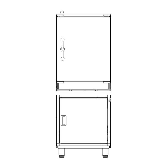
Medium Duty Electric Atmospheric Steamers
OE7503, OE7505
Please make a note of your product details for
future use:
Date Purchased:_________________________
Model Number:__________________________
Serial Number:__________________________
Dealer:_________________________________
_______________________________________
IS 469 ECN 3607
Page 1 of 15
Advertisement
Table of Contents

Subscribe to Our Youtube Channel
Related Manuals for Lincat OE7503


Summary of Contents for Lincat OE7503
- Page 1 User, Installation, Servicing and Conversion Instructions Medium Duty Electric Atmospheric Steamers OE7503, OE7505 Please make a note of your product details for future use: Date Purchased:_________________________ Model Number:__________________________ Serial Number:__________________________ Dealer:_________________________________ _______________________________________ IS 469 ECN 3607 Page 1 of 15...
-
Page 2: Table Of Contents
WARNING! This symbol is used whenever there is a risk of personal injury. CAUTION! This symbol is used whenever there is a risk of damaging your Lincat product. NOTE: This symbol is used to provide additional information, hints and tips. -
Page 3: Warnings And Precautions
Ensure that the plug/socket is accessible at all times. Strip plastic coating and clean the appliance before use. During operation parts may become hot - avoid accidental contact. Disconnect this appliance before servicing, maintenance or cleaning. TECHNICAL DATA OE7503 OE7505 Height (mm) 1600 Width (mm) -
Page 4: Installation And Commissioning
INSTALLATION AND COMMISSIONING This appliance must be earthed. An equipotential bonding terminal is provided to allow cross bonding with other equipment. When installing, connect the terminals as follows: Green and Yellow wire Earth Blue wire Neutral N Brown wire Live Install this appliance on a level surface ensuring all vents are unobstructed. - Page 5 Water supply and connection Install in accordance with BS EN 1717 and the National Water Regulations in Use. Connection is at the rear of the appliance via a 15mm compression fitting with check valve (Fig 2). When making the connection to the appliance, fit an isolating cock into the supply line, close to the appliance, for emergency shutdown or servicing purposes.
-
Page 6: Operating Instructions
Connect via a suitable isolating switch, which should be easily accessible in the event of an emergency. Connection is made at the rear of the appliance, behind the lower rear panel (Fig 2 – panel removed for clarity). Release the protective cover on the terminal housing using a flat bladed screwdriver and fit the cable into the strain relief and then the terminal block. - Page 7 Operating sequence Ensure that the water and electric isolation valves are open before attempting to operate the appliance. The tank will automatically fill with water to the correct level. NEVER OPERATE WHEN TANK IS EMPTY. Open the lower compartment door to gain access to the controls (Fig 3). Check water level is between the indicator marks (Fig 4 - A).
- Page 8 When operating, do not open the door when the steamer is hot. First slacken off the handle and allow steam to vent around the door opening. Wait 15-20 seconds before slowly opening the door fully. This precaution prevents a sudden discharge of steam into the operators face.
-
Page 9: Cleaning
Draining oven chamber Allow the appliance to cool. Turn off the water supply and place a suitable receptacle beneath the valve. Push the safety latch to the left (Fig 6 A) and open the drain tap handle (Fig 6 B). Fig 6 CLEANING Do not use a water jet or steam cleaner, and do not immerse this appliance. -
Page 10: Servicing, Maintenance And Component Replacement
Ensure the appliance is cool and both water and electricity supplies are isolated, then open drain taps, remove oven furniture and clean all panels with warm water and mild detergent, do not use abrasive materials. Rinse and dry with a soft cloth. Do not use any products containing chlorine or hydrochloric acid. - Page 11 Routine service Carry out a general check of the installation, paying particular attention to the following: Has the appliance been installed with the correct supply cable? Does the appliance have separate isolation valve for the water supply? Is there a suitable isolation switch in the electricity supply? Check all components for correct operation, and replace where necessary, following the appropriate instructions.
- Page 12 Contactor Remove the control panel from inside the lower compartment (secured by 5 screws). Disconnect the cables to the contactor, noting their position. Unclip the contactor from the mounting rail. Fit new contactor and reassemble in reverse order. Control thermostat Remove the control panel from inside the lower compartment (secured by 5 screws).
-
Page 13: Fault Finding
FAULT FINDING Explanation of the control system The appliance is fitted with a pre-set control thermostat together with a safety thermostat. Neither is operator accessible. When the water and electricity isolating supplies are switched on and the water inlet tap is open, water is allowed into the reservoir and then into the cooking chamber. Once the correct water level is reached, the green switch is pressed, the amber neon illuminates and all 3 elements are energised. -
Page 14: Spare Parts List
Check valve EL01 Element FL29 Float valve FL30 Ball float MC01 Magnetic catch NE40 Amber neon SE38 Door seal SH116 Shelf OE7503 SH114 Shelf OE7505 SW69 Switch (green) TH106 Control thermostat TH109 Safety thermostat ACCESSORIES Part Number Description Used on SH114... -
Page 15: Service Information And Guarantee
All available on serial plate Type number Serial number Lincat reserve the right to carry out any work under warranty, given reasonable access to the appliance, during normal working hours, Monday to Friday, 08:30 to 17:00. GUARANTEE This unit carries a comprehensive UK mainland 2 year warranty. The guarantee is in addition to, and does not diminish your statutory or legal rights.
Need help?
Do you have a question about the OE7503 and is the answer not in the manual?
Questions and answers