Table of Contents
Advertisement
Quick Links
GS+ / G+ MODULE
CE 0063BP3341
0.0
NOx BP005
0.0
0.0
0.0
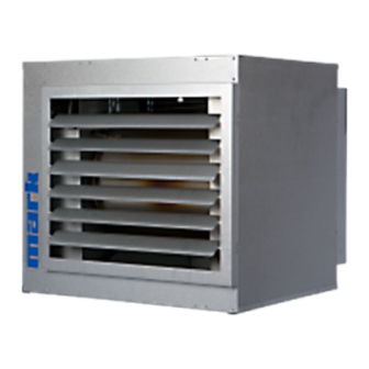
GASFIRED (MODULATING) CONDENSING PREMIX HIGH EFFICIENCY UNIT AIR HEATER
G A S B E F E U E R T E ( M O D U L I E R E N D E ) B R E N N W E R T W A R M L U F T E R Z E U G E R
A É R O T H E R M E G A Z M O D U L A N T À C O N D E N S A T I O N ( S U S P E N D U )
GASGESTOOKTE CONDENSERENDE MODULERENDE (HANGENDE) LUCHTVERWARMER
TECHNICAL MANUAL
TECHNISCHES HANDBUCH
LIVRET TECHNIQUE
TECHNISCH BOEK
Advertisement
Table of Contents


Need help?
Do you have a question about the G+ Series and is the answer not in the manual?
Questions and answers