
Related Manuals for Mark G(N)SD Series


Summary of Contents for Mark G(N)SD Series
- Page 1 Technical manual Technisches Handbuch Livret technique Technisch boek Instrukcja techniczna Manual tehnic Technická dokumentácia Technická dokumentace...
- Page 3 Read this document before installing the appliance Warning 1.0 General 1.1 Application Subject to change 1.2 Type indication...
- Page 4 Flue fan inlet orifice diameter to specific type Flue fan bypass orifice diameter to specific type Restriction ring for short vertical flue system to specific category Restriction ring for short horizontal flue system to specific category 1.3 Warnings General warnings Appliance Gas supply and connection Flue gas discharge and outlet for flue duct/exhaust pipe...
-
Page 6: Installation
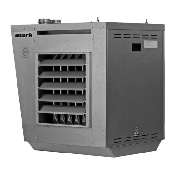
1.4 Think of your safety 2.0 Installation 2.1 Positioning the appliance [2 & 3] 2.2 Positioning the flue gas exhaust system and air supply C32 Flue gas exhaust system C12 Flue gas exhaust system Put the flue gas system into position and attach it correctly according to the installation instructions for the flue gas discharge system. - Page 7 Device type Nominal diameter 2.3 Gas connection 2.4 Electrical connection 2.5 Room thermostat and reset button [17] [15] [16] 2.6 Choice of bus cable...
- Page 8 3.0 Start-up/shutdown 3.1 General 3.2 Appliance address details [16] [18] [18] 3.3 Control activities 3.4 Check that the room thermostat is functioning correctly 3.5 Check the nominal pressure...
-
Page 9: Maintenance
3.6 Check the pre-pressure 3.8 Shutting down the heater For short periods of time: For longer periods of time: 4.0 Maintenance 4.1 General 4.2 Cleaning Burner tray. -
Page 10: Description Of Parts
[13] 5.0 Description of parts General 5.1 Automatic ignition control and gas combination units [6] SIT Sigma 840 order code 0608050 in appliances 20, 22, 25, 27, 30, 35, 40, 45, 50 and 56. SIT Nova 822 order code 0608057 in appliances 60, 65, 80, 90, and 95. 5.2 Ionisation and ignition [8] Ionisation electrode order code 06 25 350 Ignition electrode order code 06 25 347... - Page 13 Lesen Sie dieses Dokument sorgfältig durch, bevor Sie das Gerät installieren Warnhinweis 1.0 Allgemein 1.1 Einsatzbereich Änderungen vorbehalten. 1.2 Typkennzeichnung...
- Page 14 1.3 Warnhinweise Allgemeine Warnhinweise Gerät Gaszufuhr und Gasanschluss Abgasstrecke...
- Page 15 1.4 Denken Sie an Ihre Sicherheit 2.0 Installation 2.1 Aufstellung des Geräts [2 und 3] 2.2 Anbringen der Abgasableitung und der Luftzufuhr Abgasableitungssystem C32 Abgasableitungssystem C12 Gerätetyp Dachdurchführung C32 Wanddurchführung C12...
- Page 16 Gerätetyp Nenndurchmesser 2.3 Gasanschluss 2.4 Elektrischer Anschluss 2.5 Raumthermostat und Rückstellknopf [17] [15] [16] 2.6 Wahl des Buskabels...
- Page 17 3.0 Inbetriebnahme/Außerbetriebnahme 3.1 Allgemeines 3.2 Adressierung des Geräts. [16] [18] [18] 3.3 Überprüfungsarbeiten...
-
Page 18: Wartung
3.4 Überprüfen Sie die Funktion des Raumthermostaten 3.5 Überprüfen Sie die Nennbelastung 3.6 Überprüfung des Vordrucks 3.8 Außerbetriebnahme des Lufterhitzers: Für kurze Zeit: 4.0 Wartung 4.1 Allgemein 4.2 Reinigung Brennerbett. -
Page 19: Beschreibung Der Bauteile
[13] 5.0 Beschreibung der Bauteile: Allgemeines 5.1 Brennerautomat und Gaskombinationsblöcke [6] SIT Sigma 840 Bestellcode 0608050 für die Geräte 20, 22, 25, 27, 30, 35, 40, 45, 50 und 56. SIT Nova 822 Bestellcode 0608057 für die Geräte 60, 65, 80, 90 und 95. 5.2 Ionisation und Zündung [8] Ionisationselektrode Bestellcode 0625349 Zündelektrode Bestellcode 0625346... - Page 20 B Ein Minimalthermostat Bestellnr. 06 29 057 [14] C/D Einer oder zwei Maximalthermostaten, Bestellnr. 31 01 935 5.4 Luftdruckschalter Bestellnr. 06 07 604 [10] 5.5 Abgaslüfter [11] 5.6 Lüfter[12] [12] 6.0 Störungscodes.
-
Page 21: Elektrischer Schaltplan
7.0 Elektrischer Schaltplan Für G(N)CT/RE: Siehe Innenseite des Geräts. - Page 23 Lire attentivement ce document avant de commencer l’installation de l’appareil Avertissement 1.0 Généralités 1.1 Utilisation 1.2 Indication du type...
-
Page 24: Avertissements Généraux
1.3 Avertissements généraux Avertissements généraux Appareil Amenée et raccordement du gaz Tracé des gaz de fumée... - Page 25 1.4 Penser à la sécurité 2.0 Installation 2.1 Mise en place de l’appareil [2 & 3] 2.2 Positionnement de l’évacuation des gaz de combustion et de l’amenée d’air C32 Système d’évacuation des gaz de fumée C12 Système d’évacuation des gaz de fumée Type d’appareil Passage de toiture C32 Passage mural C12...
- Page 26 Type d’appareil Diamètre nominal 2.3 Raccordement gaz 2.4 Raccordement électrique 2.5 Thermostat et bouton de réarmement [17] [15] [16] 2.6 Choix du câble bus...
- Page 27 3.0 Mise en service / mise hors service 3.1 Généralités 3.2 Adressage de l’appareil [16] [18] [18] 3.3 Travaux de contrôle 3.4 Vérification du fonctionnement du thermostat...
-
Page 28: Entretien
3.5 Contrôle de la charge nominale 3.6 Contrôle de la pré-pression 3.8 Mise hors service du dispositif de chauffage Pour une période courte: Pour une période plus longue : 4.0 Entretien 4.1 Généralités 4.2 Nettoyage Caisson du brûleur. -
Page 29: Description Des Éléments
[13] 5.0 Description des éléments Généralités 5.1 Brûleur automatique et blocs gaz combinés [6] Code de commande 0608050 du SIT Sigma 840 pour les appareils 20, 22, 25, 27, 30, 35, 40, 45, 50 et 56. Code de commande 0605057 du SIT Nova 822 pour les appareils 60, 65, 80, 90 et 95. 5.2 Ionisation et allumage [8] Code de commande 06 05 349 de l’électrode d’ionisation Code de commande 06 05 346 de l’électrode d’allumage... -
Page 30: Codes Erreur
C/D Un ou deux thermostat(s) maximum, code de commande 31 01 935 5.4 Interrupteur de pression atmosphérique, code de commande 06 07 604 [10] 5.5 Ventilateur des gaz de fumée [11] 5.6 Ventilateur [12] [12] 6.0 Codes erreur. -
Page 31: Schéma Électrique
7.0 Schéma électrique. - Page 33 Lees dit document door voordat u aan de installatie van het toestel begint Waarschuwing 1.0 Algemeen 1.1 Toepassing LET OP! Wijzigingen voorbehouden 1.2 Typeaanduiding...
-
Page 34: Algemene Waarschuwingen
1.3 Algemene waarschuwingen Algemene waarschuwingen Toestel Gastoevoer en gasaansluiting. Rookgas tracé... - Page 35 1.4 Denk aan uw veiligheid 2.0 Installatie 2.1 Plaatsing toestel [2 & 3] Note: 2.2 Plaatsing Verbrandingsgasafvoer en luchttoevoer. C32 Rookgasafvoersysteem C12 Rookgasafvoersysteem Type toestel Dakdoorvoer C32 Muurdoorvoer C12...
- Page 36 Type toestel Nominale diameter 2.3 Gasaansluiting 2.4 Elektrische aansluiting LET OP! 2.5 Ruimtethermostaat en resetknop LET OP! [17] [15] [16] 2.6 Keuze buskabel...
- Page 37 3.0 Inbedrijfstelling / buiten bedrijfstelling 3.1 Algemeen 3.2 Adressering van het toestel [16] [18] [18] 3.3 Controlewerkzaamheden 3.4 Controleer de werking van de ruimtethermostaat...
- Page 38 3.5 Controle van de nominale belasting 3.6 Controle van de voordruk 3.8 Buitenbedrijf stellen van de verwarmer Voor korte tijd: Voor langere tijd: 4.0 Onderhoud 4.1 Algemeen 4.2 Reiniging Branderbed.
-
Page 39: Beschrijving Van Onderdelen
[13] 5.0 Beschrijving van onderdelen Algemeen 5.1 Branderautomaat en Gas combinatieblokken [6] SIT Sigma 840 bestelcode 0608050 op de toestellen 20, 22, 25, 27, 30, 35, 40, 45, 50 en 56. SIT Nova 822 bestelcode 0608057 op de toestellen 60, 65, 80, 90 en 95. 5.2 Ionisatie en ontsteking [8] Ionisatie elektrode bestelcode 06 25 350 Ontsteek elektrode bestelcode 06 25 347... -
Page 40: Storing Codes
5.4 Luchtdrukschakelaar bestelcode 06 07 604 [10] 5.5 Rookgasventilator [11] 5.6 Ventilator [12] [12] 6.0 Storing codes. - Page 41 7.0 Elekrisch schema...
- Page 43 Proszę przeczytać niniejszy dokument przed instalacją urządzenia Ostrzeżenie 1.0 Opis ogólny 1.1 Zastosowanie Zastrzeżone prawo do modyfikacji 1.2 Oznaczenie typu...
- Page 44 1.3 Ostrzeżenia ogólne Ostrzeżenia ogólne Urządzenie. Zasilanie gazem i podłączenie gazu. Odprowadzanie spalin i pobór powietrza do spalania...
- Page 45 1.4 Pomyśl o swoim bezpieczeństwie 2.0 Montaż 2.1 Ustawianie urządzenia [2 & 3] 2.2 Ustawianie kanału spalinowego i doprowadzenia powietrza Układ odprowadzania spalin typu C32 Układ odprowadzania spalin typu C12...
- Page 46 Typ urządzenia Odprowadzanie spalin Odprowadzanie spalin pionowe C32 poziome C12 Typ urządzenia Średnica nominalna 2.3 Przyłącze gazowe 2.4 Przyłącze elektryczne 2.5 Termostat pomieszczeniowy i przycisk resetowania...
- Page 47 [17] [15] [16] 2.6 Wybór przewodu magistrali 3.0 Uruchomienie / Wyłączenie 3.1 Opis ogólny 3.2 Informacje dotyczące adresu urządzenia [16] [18] [18] 3.3 Czynności kontrolne...
- Page 48 3.4 Sprawdzić, czy termostat pomieszczeniowy działa prawidłowo 3.5 Sprawdzenie ciśnienia nominalnego 3.6 Sprawdzenie ciśnienia wstępnego 3.8 Wyłączanie nagrzewnicy Na krótki okres czasu: Na dłuższe okresy czasu:...
-
Page 49: Opis Części
4.0 Konserwacja 4.1 Informacje ogólne 4.2 Czyszczenie Płyta z palnikami. [13] 5.0 Opis części. Informacje ogólne 5.1 Automatyczne sterowanie zapłonem i elementy układu gazowego [6], [7] 20, 22, 25, 27, 30, 35, 40, 45, 50 i 56 60, 65, 80, 90 i 95... - Page 50 5.2 Jonizacja i zapłon [8] 5.3 Układy termostatów [9] A Pojedynczy termostat bezpieczeństwa (STB), numer katalogowy 31 01 655 B Pojedynczy termostat temperatury minimalnej, numer katalogowy 06 29 057 [14] C/D Jeden lub dwa termostaty temperatury maksymalnej, numer katalogowy 31 01 935 5.4 Przełącznik ciśnieniowy, numer katalogowy 06 07 604 [10] 5.5 Wentylator spalin [11] 5.6 Wentylator [12]...
- Page 51 6.0 Kody zakłóceń.
-
Page 52: Schemat Elektryczny
7.0 Schemat elektryczny... - Page 53 Citiţi acest document înainte de a instala aparatul Avertisment 1.0 Informaţii generale 1.1 Instalarea Posibile schimbări 1.2 Indicarea tipului...
- Page 54 1.3 Atenţionări generale Atenţionări generale Aparat Alimentarea cu gaz şi conectarea Calea de evacuare a gazului...
- Page 55 1.4 Gândiţi-vă la siguranţa dvs 2.0 Instalarea 2.1 Poziţionarea instalaţiei [2 & 3] 2.2 Poziţionarea sistemului de evacuare a gazului şi alimentării cu aer Sistem de evacuare a gazului C32 Sistem de evacuare a gazului C12 Tip dispozitiv Ţeavă plafon C32 Ţeavă...
- Page 56 2.3 Conectarea la gaz 2.4 Conexiunea electrică 2.5 Termostatul de cameră şi butonul de resetare [17] [15] [16] 2.6 Alegerea cablului de magistrală...
-
Page 57: Pornire / Oprire
3.0 Pornire / oprire 3.1 Informaţii generale 3.2 Detaliile de adresare a aparatului [16] [18] [18] 3.3 Controlarea... - Page 58 3.4 Verificaţi dacă termostatul de cameră funcţionează corect 3.5 Verificaţi presiunea nominală 3.6 Verificaţi pre-presiunea 3.8 Oprirea încălzitorului Pentru perioade scurte de timp: Pentru perioade lungi de timp: 4.0 Întreţinerea 4.1 Informaţii generale 4.2 Curăţarea Rampa arzătorului.
- Page 59 [13] 5.0 Descrierea pieselor Informaţii generale 5.1 Controlul automat al aprinderii şi unităţile de combinare a gazului [6] 20, 22, 25, 27, 30, 35, 40, 45, 50 60, 65, 80, 90 5.2 Ionizare şi aprindere [8] 5.3 Îmbinare termostat [9] A Un termostat de siguranţă...
- Page 60 B Un termostat la temperatură minimă, cod de comandă 06 29 057 [14] C/D Unul sau două termostate la temperatură maximă, cod de comandă 31 01 935 5.4 Indicator pneumatic, cod de comandă 06 07 604 [10] 5.5 Ventilator de evacuare a gazului [11] 5.6 Ventilator [12] [12] 6.0 Coduri de defecţiune.
- Page 61 7.0 Schiţa circuitului electric...
- Page 63 Pred inštaláciou zariadenia si prečítajte tento dokument Výstraha 1.0 Všeobecné 1.1 Použitie Predmet zmeny 1.2 Označenie typu...
-
Page 64: Všeobecné Upozornenia
1.3 Všeobecné upozornenia Všeobecné upozornenia Zariadenie Prívod plynu a pripojenie Smer spalinového plynu... - Page 65 1.4 Myslite na svoju bezpečnosť 2.0 Inštalácia 2.1 Umiestnenie zariadenia [2 & 3] 2.2 Umiestnenie odsávacieho systému spalinového plynu a prívod vzduchu C32 Odsávací systém spalinového plynu C12 Odsávací systém spalinového plynu Typ zariadenia Prechod cez strechu C32 Prechod cez stenu C12...
- Page 66 Typ zariadenia Nominálny priemer 2.3 Plynová prípojka 2.4 Elektrická prípojka 2.5 Izbový termostat a reštartovacie tlačidlo [17] [15] [16] 2.6 Výber kábla spojovacieho vedenia...
- Page 67 3.0 Spustenie do prevádzky/vypnutie 3.1 Všeobecné 3.2 Podrobnosti o adrese zariadenia [16] [18] [18] 3.3 Kontrolné činnosti 3.4 Dôkladne skontrolujte, či izbový termostat funguje správne 3.5 Skontrolujte nominálny tlak...
- Page 68 3.6 Kontrola vopred nastaveného tlaku 3.8 Vypnutie ohrievača. Na krátke obdobie: Na dlhšie časové obdobie: 4.0 Údržba 4.1 Všeobecné 4.2 Čistenie Blok horáka.
-
Page 69: Popis Častí
[13] 5.0 Popis častí Všeobecné 5.1 Riadenie automatického zapaľovania a kombinované plynové jednotky [6] 20, 22, 25, 27, 30, 35, 40, 45, 50 a 56 60, 65, 80, 90 a 95 5.2 Ionizácia a zapálenie [8] 5.3 Kombinácia termostatov [9] A Jeden bezpečnostný... - Page 70 5.4 Spínač tlaku vzduchu, objednávací kód 06 07 604 [10] 5.5 Ventilátor spalinového plynu [11] 5.6 Ventilátor [12] [12] 6.0 Kódy chýb.
-
Page 71: Elektrická Schéma
7.0 Elektrická schéma... - Page 73 Před instalací zařízení si přečtěte následující manuál Varování 1.0 Všeobecné informace 1.1 Použití Nezávaznost změn 1.2 Označení typů zařízení...
- Page 74 1.3 Všeobecná upozornění Všeobecná upozornění Zařízení Plynová přípojka a napájení plynem Spalinová dráha plynu...
- Page 76 1.4 Dbejte na svoji bezpečnost 2.0 Instalace 2.1 Umístění zařízení do stanovené polohy [2 & 3] 2.2 Umístění výfukového systému spalin plynu a napájení vzduchem. C32 Výfukový systém spalin plynu C12 Výfukový systém spalin plynu Typ zařízení Střešní průchod C32 Průchod zdí...
- Page 77 Typ zařízení Nominální průměr 2.3 Připojení plynu 2.4 Připojení na elektrické napájení 2.5 Pokojový termostat a tlačítko vynulování [17] [15] [16] 2.6 Výběr sběrnicového kabelu...
- Page 78 3.0 Spuštění/odstavení z provozu 3.1 Všeobecné informace 3.2 Podrobné informace o adresování zařízení [16] [18] [18] 3.3 Vykonávané kontroly 3.4 Kontrola správné funkčnosti pokojového termostatu 3.5 Kontrola nominálního tlaku...
- Page 79 3.6 Kontrola předtlaku 3.8 Odstavení otopného tělesa z provozu. Krátkodobě: Dlouhodobě: 4.0 Údržba 4.1 Všeobecné informace 4.2 Čištění Hořáková deska.
-
Page 80: Popis Dílů
5.0 Popis dílů Všeobecné pokyny 5.1 Automatické ovládání vznícení a kombinované plynové jednotky [6] 20, 22, 25, 27, 30, 35, 40, 45, 50 a 56 60, 65, 80, 90 a 95 5.2 Ionizace a zapálení [8] 5.3 Kombinace termostatu [9] A jeden bezpečnostní... - Page 81 5.4 Spínač tlaku vzduchu, objednávací číslo 06 07 604 [10] 5.5 Ventilátor spalin plynu [11] 5.6 Ventilátor [12] [12] 6.0 Kódy závad.
- Page 82 20/22 75 - 2800 250 1115 130 25/27 75 - 2800 250 1115 130 30/35 75 - 3000 250 1115 130 40/45 1014 75 - 3200 250 1115 130 50/56 1104 1144 75 - 3400 250 1115 160 60/65 1289 1254 1010 75 - 3600 250...
- Page 87 MAX I (°C) MAX II (°C) 20/22 25/27 30/35 40/45 50/56 60/65 80/90/95 [10]...
- Page 88 [11] code 20/35 31 03 275 40/56 31 03 276 60/95 31 03 277 [12] code 20/27 31 09 001 30/35 31 09 002 40/45 31 09 003 50/56 31 09 004 60/65 (2x) 31 09 002 80/95 (2x) 31 09 003...
- Page 89 [13] [14]...
- Page 90 [15] [16]...
- Page 91 [17] MOD E °C HEAT AUTO MOD E °C HEAT AUTO MOD E °C HEAT AUTO =Lb (max.) =La (max.) =Lc+Ld (max.) 0.8mm 160m 800m 1.0mm 200m 1000m 1.5mm 300m 1500m 2.5mm 500m 2500m [18] MOD E MOD E °C °C HEAT HEAT...
- Page 92 TELEFOON +31(0)598 656600 FAX +31 (0)598 624584 info@mark.nl info@mark.de www.mark.nl www.mark.de MARK EIRE BV MARK POLSKA Sp. z o.o COOLEA, MACROOM UL. KAWIA 4/16 CO. CORK (IRELAND) 42-200 CZE ˛STOCHOWA (POLSKA) PHONE +353 (0)26 45334 PHONE +48 34 3683443 FAX +353 (0)26 45383 FAX +48 34 3683553 sales@markeire.com...
Need help?
Do you have a question about the G(N)SD Series and is the answer not in the manual?
Questions and answers