Advertisement
Quick Installation Guide
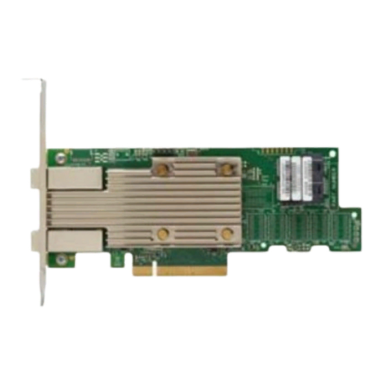
9400-8i8e Tri-Mode Host Bus Adapter
Thank you for purchasing the Host
Bus Adapter (HBA). Please take a few
minutes to read this quick
installation guide before you install
the HBA.
ATTENTION:
Perform all installation work at
an electrostatic discharge (ESD)-
safe workstation that meets the
requirements of EIA-625.
Requirements for Handling
Electrostatic Discharge Sensitive
. You must perform all
Devices
actions in accordance to the
latest revision of the IPC-A-610
ESD-recommended practices.
Hardware Installation Instructions
To install the Tri-Mode HBA, follow these steps:
1.
Unpack the adapter, and inspect it for damage. Unpack the adapter in a static-free environment.
Remove the adapter from the antistatic bag, and carefully inspect the device for damage. If you notice
any damage, contact a Broadcom
ATTENTION:
To avoid the risk of data loss, back up your data before you change your system
configuration.
Prepare the computer. Turn off the computer, and disconnect the power cord from the rear of the
2.
power supply.
CAUTION:
Disconnect the computer from the power supply and from any networks to which you
will install the adapter, or you risk damaging the system or experiencing electrical
shock.
Remove the cover from the chassis.
3.
Check the mounting bracket on the adapter (system dependent). If required for your system,
4.
replace the full-profile mounting bracket that ships on the adapter with the low-profile bracket supplied.
Complete the following steps to attach the low-profile bracket.
a.
Using a No.1 Phillips screwdriver that is ESD safe, remove the two Phillips screws that connect
the full-profile bracket to the board. Unscrew the two screws located at the top and bottom edges
of the board. Avoid touching any board components with the screwdriver or bracket.
Remove the full-profile bracket. Do not damage the adapter.
b.
Place the adapter on top of the low-profile bracket. Position the bracket so that the screw holes
c.
in the tabs align with the openings in the board.
Using a No.1 Phillips torque screwdriver that is ESD safe, set it to a maximum torque of 4.8 ±
d.
0.5 inch-pounds. Replace the two Phillips screws removed in step a.
ATTENTION:
Exceeding this torque specification can damage the board, connectors, or screws, and can
void the warranty on the board.
Insert the adapter into an available PCIe slot. Locate an empty x8 PCIe slot adequate for your
5.
board. Remove the blank bracket panel on the rear of the computer that aligns with the empty PCIe slot.
Save this bracket screw, if applicable. Align the adapter to a PCIe slot. Press down gently, but firmly, to
seat the adapter correctly in the slot. The following figure shows how to insert the adapter into a PCIe
slot.
NOTE: The shape, size, and locations of the components on your adapter and its bracket might vary
from this illustration. The adapter requires an x8 PCIe slot.
®
representative or your reseller sales and support representative.
Advertisement
Table of Contents

Related Manuals for Broadcom 9400-8i8e


Summary of Contents for Broadcom 9400-8i8e
-
Page 1: Quick Installation Guide
Quick Installation Guide 9400-8i8e Tri-Mode Host Bus Adapter Hardware Installation Instructions To install the Tri-Mode HBA, follow these steps: Unpack the adapter, and inspect it for damage. Unpack the adapter in a static-free environment. Remove the adapter from the antistatic bag, and carefully inspect the device for damage. If you notice ®... - Page 2 PCIe Slot Edge of Motherboard Connect the cables between the adapter and the mid-plane or storage devices. The 9400-8i8e Tri-Mode HBA has two SFF-8643 internal x4 mini- SAS HD connectors and two SFF-8644 external x4 mini-SAS HD connectors. • For SAS/SATA connections, connect standard 12Gb/s SAS cables with internal or external mini-SAS HD connectors on one end to the adapter and the appropriate connector on the other end to attach to the backplane, enclosure, or SAS/SATA devices.
- Page 3 Each leg of the U.2 enabler cable must connect to adjacent drives; otherwise, the LEDs might not work properly. It does not matter which leg of the cable is plugged into which connector pair as long as adjacent pairs are used. For more information on NVMe LED functionality, refer to the Broadcom MegaRAID and HBA Tri-Mode Storage Adapters User Guide.
-
Page 4: Technical Support
Broadcom, the pulse logo, Connecting everything, Avago Technologies, Avago, and the A logo, and MegaRAID are among the trademarks of Broadcom in the United States, certain other countries and/or the EU. Any other trademarks or trade names mentioned are the property of their respective owners.
Need help?
Do you have a question about the 9400-8i8e and is the answer not in the manual?
Questions and answers