Table of Contents
Advertisement
Quick Links
Advertisement
Table of Contents

Related Manuals for HygroMatik MiniSteam MS5


Summary of Contents for HygroMatik MiniSteam MS5
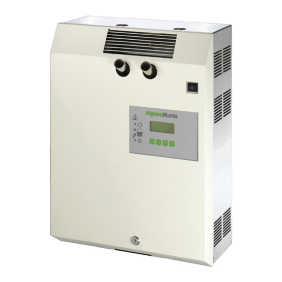
- Page 1 Manual Electrode Steam Humidifier MiniSteam ÁMS.ENUÈ MS.EN...
- Page 2 Consult your HygroMatik specialists. W e will test the quality of your wat er and advise yo u on installation and initial operation. Your Hygro Matik ste am humidifier will be carefully ad apted to your particular application.
-
Page 3: Table Of Contents
1. Introduction ........................5 1.1 Directions for Use ......................5 1.2 Typographic Distinctions ....................6 1.3 Documentation ........................6 2. Safety Notes ........................7 2.1 Overview ........................... 7 2.2 Guidelines for Safe Operation ................... 7 2.3 Disposal after Dismantling ....................8 3. - Page 4 8.7 Cleaning the Water Inlet Solenoid Valve ................36 8.8 Chekking Cable Connections and Electrode Cables ............37 8.9 Checking Operation ......................37 8.10 Dismantling ........................37 9. Commissioning ......................... 38 10. EC-Declaration of Conformity ..................39 11. Spare Parts ........................40 12.
-
Page 5: Introduction
They will impress you with their safety, ease of use and econom- ical operation. In order to op erate your HygroMatik stea m humidifier safely , properly and efficiently, please read these operating instructions. Employ yo ur ste am hu midifier only in sound condition a nd as directed. -
Page 6: Typographic Distinctions
Upper threshold Warning: HygroMatik steam humidifiers emit steam with a tem- perature of 100° C. The steam may not be inhaled directly. The HygroMatik Steam Humidifier is not designed for outdoor fit- ting. 1.2 Typographic Distinctions preceded by a bullet: general specifications. -
Page 7: Safety Notes
2. Safety Notes 2.1 Overview These sa fety notes are required b y law . The y p romote work- place safety and accident prevention. Warnings and Safety Symbols The safety symbols be low identify sections containing warnings about hazards or pot ential da ngers. Please fa miliarize yourself with these symbols. -
Page 8: Disposal After Dismantling
Attention: In t he e vent of leaky or faulty components un con- trolled hot steam may flow. HygroMatik steam humid ifiers a re IP20 -protected. Make sure that the unit is protected from drips in its installed location. Installing a humidifier in a room without water discharge requires safety devices to protect against water leakages. -
Page 9: Transport
3. Transport 3.1 Overview Note: Proceed carefully when transporting the steam humidifier in order to prevent damage due to stress or careless loading and unloading. 3.2 Carton outer Size and Weight HyLine: Type* Height Width Depth Weight [cm] [cm] [cm] [kg] HY05- 08 HY13- 17... -
Page 10: Packing
3.3 Packing Note: Notice the symbols affixed to the packing box. 3.4 Interim Storage Store the unit in a dry place and protect from frost. 3.5 Check for Complete and Correct Delivery of Goods Upon receipt of the unit, confirm that: the type and serial number on the name plate match •... -
Page 11: Operation And Installation
4. Operation and Installation 4.1 Mode of Operation The Hygro Matik steam humidifier utilizes th e con ductivity nor- mally pre sent in t ap water for steam production . Electr odes inside an enclosed steam cylinder are immersed directly into the tap water. - Page 12 Please also see Section „Exploded View“. Location Designation steam nozzle vent pipe max. water level sensor electrode water drain, discharge top part of steam cylinder o-ring cylinder flange cylinder flange and o-ring lower part of cylinder solenoid valve water inlet blow-down pump o-ring cylinder base...
- Page 13 The concentration of dissolved sa lts increases over time, which can lead to a rise in the co nductivity of th e water. If this co ntin- ues, conductivity may increase until a short circuit occurs. This could dama ge the unit, but in any case wo uld significan tly reduce the life span of the electrodes.
- Page 14 The steam cylinder consist s of a top ( 16) an d lo wer (19) p art joined with a cylinder flange. The seal between the cylinder and cylinder base (37), as well as between the top and lower part of the cylinder, is maintained by o-rings (17, 35).
-
Page 15: Installation
5. Installation Warning: Installation of this unit to be attempted only b y quali- fied pe rsonnel. We accept no liability for dama ge due to fau lty installation. Obey all safety notes and warnings present on the unit. During installation the unit must be d isconnected from its power supply. -
Page 16: Fitting Measures
5.1.1 Fitting measures Wall Distances [mm] > 150 Page 16... -
Page 17: Unit Installation Check
Wall Mounting Note: The steam humidifier must be inst alled vertically in order to function properly. Note: Th e steam hu midifier should be po sitioned such that draught ef fects are a voided. The minimum h eight is 0.1 5 m above floor level but we propose a height of 2m in order to avoid scalding. -
Page 18: Unit Dimensions
Unit Dimensions Waste water connection Cable entries Water inlet Page 18... -
Page 19: Water Installation
Note: Please contact HygroMatik if you wish to operate the unit Page 19... -
Page 20: Water Supply
Note: Shut-off valve (SV) and wate r filter (WF) are not supplied with the unit » HygroMatik provides a water hose (56) with a cap nut at both ends which can be used for water installation. Install as follows: »... -
Page 21: Water Discharge
strainer must be placed inside the solenoid valve. » Use a cap nut (internal thread ¾“) with inner seal for a customer-provided water installation. 6.3 Water discharge Warning: During blow down hot wat er wit h a temperature of about 95°C is being drained. If touched this can cause burns to the skin. -
Page 22: Water Installation Check
6.4 Water Installation Check Go down the following water installation checklist: Are all screws and clamps properly tightened? Is the water supply pipe flushed? Was the water installation correctly installed? Can the blow-down water drain freely? Was the water discharge correctly installed? ... -
Page 23: Electrical Connection
7. Electrical Connection Danger, Hazardous Voltage: All work related to electrical instal- lation to be performed by authorized personnel only (electricians or professionals with e quivalent training). Th e customer is responsible for checking qualifications. Danger, Hazardous Voltage: Do not p lug the steam humidifier into the power grid until after all installation work has been com- pleted. - Page 24 Type Standard Main Power Supply HY05 - HY45 1 x 400V/3Phase/N HY60 - HY116 2 x 400V/3Phase/N C01, C02 1 x 230/1Phase/N C06 - C58 1 x 400V/3Phase/N MS5, MS10 1 x 400V/3Phase/N 1 x 230/1Phase/N C01Kit, C02Kit 1 x 230V/1Phase C06Kit - C45Kit 1 x 400V/3Phase/N Other voltages are available on request.
-
Page 25: Cable Connections
MiniSteam: Type Power Usage Circuit Protection MS5, 230V/1/N 15,7 A 1 x 16 A MS5, 400V/3/N 5,4 A 3 x 6 A MS10, 400V/3/N 10,8 A 3 x 16 A CompactLine KIT: Type Power Usage Circuit Protection C01KIT, 230V/1/N 3,3 A 1 x 6 A C02KIT, 230V/1/N 6,5 A... -
Page 26: Safety Interlock
7.3 Safety Interlock Note: Install co ntact interlo cks, i. e. ma x. hygrostat, vane relay, pressure con troller, air inte rlock, in series bet ween terminals 1 and 2. Warning: A max-hygrostat should be installed in the safety inter- lock. -
Page 27: Maintenance
8. Maintenance The HygroMatik steam humidifier is easy to maint ain. However, inadequate or improper main tenance can le ad to o perational malfunctions. Perform regular mainte nance to give your u nit a long life span. Warning: When performing maintenance work, please note: During operation and also for a while after switching off •... -
Page 28: Maintenance Work
In extre me cases, water pretre atment may be necessary (sof t- ening by dilution to ap prox. 4 - 8 °d H; decarbon ization/partial desalination to ach ieve t arget red uctions in carbona te hard- ness). For any question regarding water treatment systems please con- tact HygroMatik. Page 28... -
Page 29: Access Electrical Enclosure
8.2 Access Electrical Enclosure » Remove cover from humidifier (B) and lift display plate (A) of guiding. » Turn display plate (please see sketch) and hang up dis- play plate by using the „front guiding“. » The basic PCB (C) is now accessable. Danger, Hazardous Voltage: Make sure the unit is switched off before installing or removing the display plate. -
Page 30: Removing And Cleaning The Steam Cylinder
8.3 Removing and Cleaning the Steam Cylinder Warning: Please follow the detailed instructions in these operat- ing in structions! The unit is only to be se rviced by qualified, authorized personnel. Note the warnings and safety notes in the operating instru ctions. F ailure to ob serve warnings a nd safety notes may result in injury, serious injury o r d eath, and/or dam- age to the unit. - Page 31 » then: lift steam cylinder out of base remove flange clamps Cleaning open cylinder remove used O-ring clean cylinder inside. Do not use acids or other clean strainer chemicals Warning: Check the inside of the top p art of steam cylinder for crust build-up and possible salt bridges (black grooves between the electrode leads).
- Page 32 Reassembly connect upper and lower insert new O-ring part with clamps remove used O-ring insert new O-ring remove old O-ring place cylinder vertically insert new O-ring into cylinder base » Connect plug (10) to level sensor. » Connect plugs (4) to electrodes. Warning: The plug must be pressed down onto the electrode as far as it will go.
-
Page 33: Electrode Wear
The hu midifier switches it self of f. Also see Se ction "Ma inte- nance." Whe n the ele ctrodes are less than 1/3 to 1/ 2 of their original length, replace them. 8.4.1 Original Electrode Lengths Original lengths of HygroMatik large area st ainless-steel e lec- trodes are: HyLine: Type... -
Page 34: Uneven Electrode Lengths
8.4.2 Uneven Electrode Lengths In mo st case, the longer e lectrode(s) will not be sup plied with electricity for a time. Therefore they will not wear. The cause of the problem, such as a tripped circuit breaker, can be re paired. However, since the sh orter electrode(s) have a grea ter specific load, the electrodes continue to wear unevenly. - Page 35 • black slime collects inside the cylinder, or • there is "lightning" in the cylinder, • the conductivity of the water is too high or it isn't decanted often enough. In this case please contact HygroMatik. Page 35...
-
Page 36: Cleaning The Blow- Down Pump
8.6 Cleaning the Blow- Down Pump » Remove cylinder, as described in Section: "Removing and Cleaning the Steam Cylinder” . » Detach e-cable from the pump. » Detach adapter (30) from the pump. » Loosen screws (44) and remove the pump from the base. -
Page 37: Chekking Cable Connections And Electrode Cables
unit housing. » Attach solenoid valve tightly with screws (28). » Screw on water installation hose. » Connect e-cable to the solenoid valve. » Attach connecting hose (21) to the base. » Install cylinder, as described in Section: "Removing and Cleaning the Steam Cylinder” »... -
Page 38: Commissioning
9. Commissioning Warning: This unit is only to be started by qualified personnel. Switching off steam humidifier Warning: Before starting up the unit, make su re you know h ow to switch it off. » Switch off unit by setting control switch to “0” »... -
Page 39: Ec-Declaration Of Conformity
10. EC-Declaration of Conformity Page 39... -
Page 40: Spare Parts
11. Spare Parts MS5 MS10 Article no. Description E-2 124010 Keys for safety, set=2pc. Safety lock incl. 2 keys E-2 124012 Steam generation B-3 216067 Steam cyl inder CY4 transp . compl. with e lectrodes and Hand nut s ** Steam cyl inder CY8 transp . - Page 41 MS5 MS10 Article no. Description Water drain Connecti ng hose pump-elbow 0,3m 0,4m E-2 604002 Adapter pump - drain hose. connections DN2 5/13 E-3 425002 O-ring seal for adapte r - pump E-3 220005 O-ring seal for cylinder base - pump E-3 220005 Drain pump without mounting set B-2 404027...
-
Page 42: Fax Form - Order For Spare Parts
12. Fax Form - Order for spare parts Fax Form Please copy, fill in and fax to Badgermeter Swiss AG . +41 (0)31 931 08 67 Mittelholzerstrasse 8 Fax.No 3006 Bern Tel. +41 (0)31 932 01 11 Order of spare parts unit type *______________ serial no.* ___________________ commission: ______________ order no.: __________________ quantity article... -
Page 43: Technical Data
13. Technical Data Technical Data Steam Humidifiers MiniSteam Type MS10 Steam Output [kg/h] Electrical Supply 230V/1/N/50-60Hz 400V/3/N/50-60Hz Electrical Power [kW][A] Current 15, 10,8 Fuse 1 x 16 * 3 x 6 * 3x 16 * Control Type Basic, Comfort Control Voltage 230V/50-60Hz Empty Weight [kg]... -
Page 44: Exploded View
14. Exploded View Page 44... -
Page 45: View Of Housing
15. View of housing Page 45... - Page 46 12/2004...
Need help?
Do you have a question about the MiniSteam MS5 and is the answer not in the manual?
Questions and answers