getAir SmartFan Installation And Operating Instructions Manual
Hide thumbs
Also See for SmartFan:
- End-of-lifetime disassembly instructions (7 pages) ,
- User manual (36 pages) ,
- Installation and operating instructions manual (32 pages)
Table of Contents
Advertisement
Quick Links
Advertisement
Table of Contents

Related Manuals for getAir SmartFan


Summary of Contents for getAir SmartFan
- Page 1 SmartFan Installation and operating instructions v 1.2_08/2016...
- Page 2 All information contained in these documents is the property of getAir GmbH & Co. KG. Any publishing thereof, whether in part or in whole, requires the written consent of getAir GmbH & Co. KG. Copying the instructions within the same company for the purpose of evaluating the product or for other product-related uses is permitted and not subject to prior approval.
-
Page 3: Table Of Contents
1 General remarks .......................... 4 2 System overview ......................... 6 2.1 Functioning .......................... 6 3 Installation preparations ......................8 3.1 SmartFan components ...................... 8 3.2 TOUCH control unit components ..................9 3.3 LED control unit components ................... 9 3.4 Dimensions ........................10 3.5 Required tools ........................10... -
Page 4: General Remarks
They are also available at www.getair.eu. Usage The SmartFan is intended for use in the controlled ventilation of rooms in houses, apart- ments, hotels, office and public buildings. It can be installed either in new buildings or in existing buildings undergoing refurbishment and/or modernisation. SmartFan usage is authorised solely in accordance with the described use cases and only in association with components recommended by getAir GmbH &... - Page 5 The following list contains descriptions of the symbols and terms used in these instructions: This hazard symbol warns about Caution the danger of injury. Hazard symbol This hazard symbol warns about Electricity the danger of electrocution. This warning symbol indicates Warning symbol Please note important information. SmartFan...
-
Page 6: System Overview
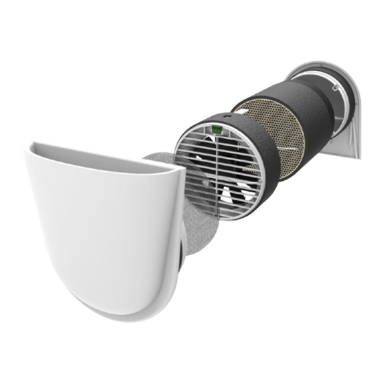
The SmartFan consists of acoustically optimised designer covers for inside (1) and out- side (2) allowing an optimal airflow, a filter unit (3), a fan unit (4), a heat exchanger unit (5) and an mounting tube (6). The SmartFan is always installed in an outside wall. The mounting tube into which the fan and heat exchanger units are inserted is sealed inside the wall. The inside and outside covers can be fitted without tools. They constitute the... - Page 7 GENERALLY SPEAKING, WET ROOMS REQUIRE (1) TWO UNITS TO BE INSTALLED, AND (2) PRECAUTIONS TO BE TAKEN THAT WET ROOM AIR DOES NOT MIX WITH THE AIR OF OTHER ROOMS. THIS SYSTEM IS NOT SUITABLE FOR WET ROOMS WITH NO OUTSIDE WALL. SmartFan...
-
Page 8: Installation Preparations
2 SmartFan outside cover 3 SmartFan fan unit 4 SmartFan heat exchanger unit Full SmartFan set 5 Mounting tube 500 mm 6 Plastering covers 7 SmartFan cap for the inside cover Article name Item Content Numbers 2 SmartFan outside cover SmartFan... -
Page 9: Touch Control Unit Components
TOUCH control unit components Article name Item Content Numbers 1 TOUCH control screen TOUCH control unit 2 Frame 3 Control base LED control unit components Article name Item Content Numbers 1 LED control panel 2 Frame LED control unit 3 Control base SmartFan... -
Page 10: Dimensions
Dimensions Required tools The following equipment is needed to install the SmartFan: • Core drill with a Ø 162 mm bit • Sabre saw for sawing plastic • Mounting adhesive / sealant to fix the mounting tube in place • 2.5 mm slot screwdriver • Hammer and chisel for cable ducts / slits • Deep pattress box for flush mounting (single or double, dependent on the choice of installation) SmartFan... -
Page 11: Positioning
Positioning The best position for the SmartFan is determined in the project planning phase. Please pay attention to the minimum distances, as otherwise no guarantee can be given that the units will function properly. > 300 mm Minimum distance to the ceiling and floor >... -
Page 12: Electrical Installation
The SmartFan home ventilation system can only be used in conjunction with a TOUCH or LED control unit. The SmartFan is controlled via a BUS system, meaning that all units can be connected to the control unit individually or serially. The control unit can be installed anywhere within a home‘s electrical system. -
Page 13: Installation Recommendations For The Control Unit
One power supply can serve up to six units. Once you exceed six SmartFan units, you will need to install a further power supply unit. Further power supply units may also be connec- ted directly to the control unit. However, when distances are long, these should be installed as far away as possible from the first power supply. Care should be taking when doing the... -
Page 14: Connection And Wiring
The connector must be wired as shown below. When connecting the plug to the fan unit holder, the screws should point downwards. When continuing the cable to a further SmartFan unit, the colours of the input and output wires in the selected plug openings must match each other. -
Page 15: Setting The Dip Switch
Zone setting Fan start direction SmartFan fan units are equipped with a DIP switch on the top. During installation, the required zone and initial direction need to be set. Switches 1 - 3 are used to assign a unit to one of the three zones available. -
Page 16: Installation
FOR CORE-DRILLING A HOLE THROUGH THE WALL. 5.1.1 Use of a prefabricated installation block Insert the pre-fabricated Neopor® installation block into the wall, following the instructions for its installation. The hole must point downwards to the outside. Cut of any protruding material so that the block is flush with the wall. SmartFan... -
Page 17: Core-Drilling A Hole Through The Wall
Core-drill a hole in the outside wall using a 162 mm bit. The hole must have a gradient of 1 – 3°, allowing any condensate to flow outwards. It is best to drill the hole from inside to outside. Inside Outside 1 - 3° WHEN CORE DRILLING, PLEASE MAKE SURE THAT THERE IS ADEQUATE PROTECTION FROM FALLING MASONRY ON THE OUTSIDE OF THE BUILDING, ENSURING THAT NO PERSON OR MATERIAL WILL BE HARMED/DAMAGED. SmartFan... -
Page 18: Inserting The Mounting Tube
When using cables with a larger diameter or when linking several SmartFan units together, the slit will need to be wider. Coat the outside of the mounting tube with the sealant (2) and insert it into the core-drilled hole (3). -
Page 19: Cabling
Remove the plastering cover and insert the outside cover into the mounting tube. Make sure that the outside cover is straight and points downwards (the air vent at the bottom). Due to the special mounting slats, the outside cover can be installed without any tools and sits tight in the mounting tube. SmartFan... -
Page 20: Installing The Heat Exchanger Unit
Make sure that the fan unit sits properly in the mounting tube and that the electrical control baseis on top. Connect the power cable to the fan unit and insert the unit carefully into the mounting tube until the spacers touch the heat exchanger. SmartFan... -
Page 21: Inserting The Inside Cover
Place the filter unit in the slots for the filter inside the cover. Insert the cover into the mounting tube, making sure that the air vent points upwards and that the cover sits tightly. THE UNITS MUST HAVE A FILTER INSERTED BEFORE BEING TURNED ON FOR THE FIRST TIME. SmartFan... -
Page 22: Operating The System
Operating the system SmartFan The inside cover can be shut, should you not use the system over a longer period or should you want to prevent smoke for instance entering the room. WHEN IN USE, THE INSIDE COVER MUST BE OPEN! 6.1.1 Shutting the inside cover... -
Page 23: Opening The Inside Cover
Step 1: Pull the inside cover out of the Step 2: Remove the cap from the air intake. mounting tube. Step 3: Store the cap in a safe and easily Step 4: Carefully reinsert the inside cover into accessible place. the mounting tube. SmartFan... -
Page 24: Touch Control Unit
Shows the current menu item. Selection area Activates different operating modes or further menu items. Last menu page Takes you back to the previous menu page. Home Takes you to the start screen. Next menu page Takes you to the next menu page. SmartFan... -
Page 25: System Set-Up
6.2.2 System set-up On starting the SmartFan system for the first time, a number of settings need to be made to ensure that the TOUCH control unit works properly. Language Time setting START Step 1: Press START to Step 2: Select the language. Step 3: Set the time. begin the set-up procedure. Number of units in Zone 1... -
Page 26: Operating Modes And Functions
The system‘s internal clock can be set. System information Show‘s the control unit‘s software version, as well as the system‘s ventilation behaviour in all zones. Initial settings Resets the control unit to its initial settings. Language selection Changes the system‘s language. SmartFan... -
Page 27: Further Functions
The system information area also shows details of the ventilation level. A thumb icon is used to show the level. Optimal ventilation Rooms are being properly ventilated. No action needed. Sufficient ventilation Rooms are being adequately ventilated. Monitor ventilation behaviour. Insufficient ventilation Rooms are not being properly ventilated. Increase the fan speed immediately. SmartFan... -
Page 28: Led Control Unit
When in this mode, the LEDs will be green. Full-blast mode The system runs in just one direction, allowing a room to be thoroughly ventilated. Heat recovery is not available in this mode. When in this mode, the LEDs will be blue. SmartFan... -
Page 29: Further Functions
„Down arrow“ and „Full-blast mode“ concurrently. Here again, the LEDs blink as confirmation. Filter change display When a filter change is required, the middle two LEDs start blinking. Once the filter has been changed, this is confirmed by pressing the two round buttons in the middle concur- rently. In doing so, the internal meter is also reset. THE OPTIMAL TIME FOR CHANGING A FILTER IS DEPENDENT ON LOCAL CONDITIONS AND CAN THUS VARY. SmartFan... -
Page 30: Cleaning And Maintenance
Cleaning and maintenance To ensure the efficient functioning of your SmartFan, all components must be regularly checked and maintained. Maintenance interval Component Interval What is to be done Inside cover/ Once every • Wipe the surface with a damp cloth. grille three months Dust filter Once every • Use a vacuum cleaner to free the filter of dust. three months • Then wash it warm water. -
Page 31: Maintenance Instructions
When necessary, clean or replace it. Step 4a - Dust filter: Step 4b - Pollen filter: Step 5: Reinsert the inside Replace the filter in its Insert the filter unit into the cover (with the air intake holder. holder with the lighter side. pointing upwards) into the mounting tube. SmartFan... -
Page 32: Fan Unit Maintenance
(with the air intake tube. Pay attention to the pointing upwards) into the power cable. Plug in the fan mounting tube. (1). Push the fan unit down into the mounting tube until the spacers touch the heat exchanger (2). SmartFan... -
Page 33: Heat Exchanger Maintenance
Push the fan unit down into ceramic parts with water! mounting tube. the mounting tube until Let the heat exchanger dry. the spacers touch the heat exchanger (2). Step 7: Reinsert the inner cover into the mounting tube (with the air vent pointing upwards). SmartFan... -
Page 34: Troubleshooting
• Clean the ventilation unit. operating in Distance between the heat • check the spacers on the fan unit. normal mode. exchanger unit and fan unit • Increase the distance. too small. Fan speed too high. • Switch to a lower speed. SmartFan... - Page 35 • Check the DIP switch settings on the fan unit. Control unit is operating in • Set the controls to Eco-mode Incoming air "full-blast" mode to thoroughly (heat recovery). is cold. ventilate the room. Heat exchanger missing. • Insert the heat exchanger. SmartFan...
-
Page 36: Disposal
Dust filter Household refuse Pollen filter Household refuse Mounting tube Collection of recyclable materials TOUCH/LED control ABS / Electrical Electronics recycling units components Please note: Do not dispose of batteries along with household waste. Take them to a battery recycling point. SmartFan... -
Page 37: Technical Data
10 Technical data 10.1 SmartFan Heat recovery rate Up to 91% Level 1 Level 2 Level 3 Level 4 Airflow in eco-mode/ventilation [m³/h] Sound pressure level [dB(A)] Power consumption Power [V] 230 AC / 50-60 Hz Input voltage [V] 12 DC SELV RS 485 AB... - Page 38 12 DC SELV Power consumption Connection RS 485 AB Type of protection IP 40 Software class Permissible operating temperatures [°C] 0 ... 40 Contamination level Dimensions [mm] 80 x 80 x 15 (WxHxD) Colour White Conformity without power supply SmartFan...
-
Page 39: Energy Efficiency Label And Product Information Sheet
11 Energy efficiency label and product information sheet 11.1 SmartFan energy efficiency label The product label lists the following details contained in the product information sheet: • Energy efficiency class • Sound power level Lwa in a room at a reference airflow volume • Highest airflow volume SmartFan TOUCH TOUCH sensor ENERGIA · · ΕΝΕΡΓΕΙΑ · ENERGIJA · ENERGY · ENERGIE... - Page 40 11.2 Product information sheet for a SmartFan with TOUCH sensor controls Produktdatenblatt (gem. VO 1254/2014 EU vom 11. Juli 2014) / Product datasheet (acc. REG 1254/2014 EU of 11 July 2014) Beschreibung / Description Werte / Data Pkt. Lieferant / Supplier‘s name getAir Modellkennung / Supplier‘s model identifier...
- Page 41 11.3 Product information sheet for a SmartFan with a TOUCH control unit Produktdatenblatt (gem. VO 1254/2014 EU vom 11. Juli 2014) / Product datasheet (acc. REG 1254/2014 EU of 11 July 2014) Beschreibung / Description Werte / Data Pkt. Lieferant / Supplier‘s name getAir Modellkennung / Supplier‘s model identifier...
- Page 42 11.4 Product information sheet for a SmartFan with a LED control unit Produktdatenblatt (gem. VO 1254/2014 EU vom 11. Juli 2014) / Product datasheet (acc. REG 1254/2014 EU of 11 July 2014) Beschreibung / Description Werte / Data Pkt. Lieferant / Supplier‘s name getAir Modellkennung / Supplier‘s model identifier...
-
Page 43: Warranty
12.1 Warranty conditions getAir GmbH & Co. KG provides a 24-month warranty on its SmartFan ventilation system (or 30 months from the SmartFan‘s date of manufacture). Warranty claims apply solely to material and/or construction faults which occur during the warranty period. Under the warranty conditions, repairs may only be carried out with getAir‘s prior written consent. - Page 44 The system has been developed and manufactured for the decentralised ventilation of homes and functional premises. Any other usage is considered to be improper and can cause damage to the SmartFan or to persons. In such a case, the manufacturer cannot be held liable. The manufacturer cannot be held liable for any damage resulting from one of the following causes: •...
-
Page 45: Attachment
Special cellar version - Shell installation set KA 100260 Replacement parts SmartFan inside cover 100400 SmartFan outside cover 100401 SmartFan fan unit 100411 SmartFan heat exchanger unit 100420 A complete list of accessories and replacement parts is available on our website: www.getair.eu SmartFan... - Page 46 13.2 Wiring protocol Initial direction Name of the room and Ventilation Floor Zone unit ventilation unit position Air intake Exhaust SmartFan...
Need help?
Do you have a question about the SmartFan and is the answer not in the manual?
Questions and answers