Table of Contents
Advertisement
Quick Links
Advertisement
Table of Contents

Related Manuals for getAir SmartFan TOUCH


Summary of Contents for getAir SmartFan TOUCH
- Page 1 SmartFan Installation and operating instructions v 1.2_08/2016...
- Page 2 We reserve the right to make partial or entire changes to these instructions without prior announcement. All information contained in these documents is the property of getAir GmbH & Co. KG. Any publishing thereof, whether in part or in whole, requires the written consent of getAir GmbH &...
-
Page 3: Table Of Contents
4.1.3 Operating modes and functions ................18 4.1.4 Further functions ......................20 4.2 LED control unit........................22 4.2.1 Control panel ........................ 22 4.2.2 Modes ..........................23 4.2.3 Further functions ......................23 5 Technical data ..........................24 6 Disposal ............................26 7 Warranty ............................27 SmartFan TOUCH/LED... -
Page 4: General Remarks
Assembly, electrical installation and system start-up should only be performed by skilled persons. These are people with relevant safety training and qualified to install, commission and label equipment, systems and cabling in accordance with current safety standards. SmartFan TOUCH/LED... - Page 5 The following list contains descriptions of the symbols and terms used in these instructions symbols and explanations: This hazard symbol warns Caution about the danger of injury. Hazard symbol This hazard symbol Electricity warns about the danger of electrocution. Please This warning symbol indicates Warning symbol note important information. SmartFan TOUCH/LED...
-
Page 6: Installation Preparations
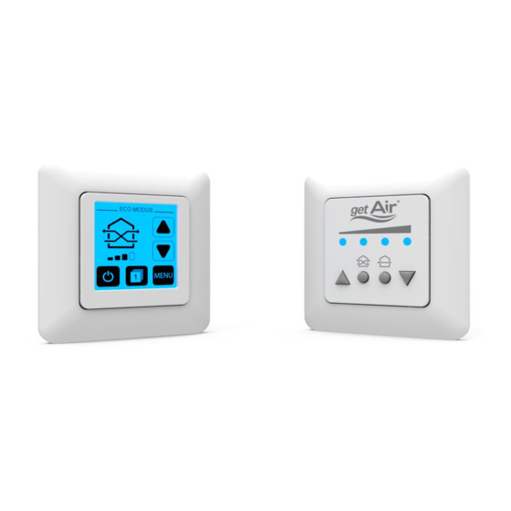
Before starting installation, please check that all components are present, as otherwise it will not be possible to complete the installation. TOUCH control unit components Article name Item Content Numbers 1 TOUCH screen Touch control unit 2 Frame 3 Control base SmartFan TOUCH/LED... -
Page 7: Led Control Unit Components
LED control unit components Article name Item Content Numbers 1 LED panel LED control unit 2 Frame 3 Control base SmartFan TOUCH/LED... -
Page 8: Dimensions
The following equipment is needed to install the SmartFan: • 2.5 mm slot screwdriver • Hammer and chisel for cable ducts / slits • Deep pattress for flush mounting (single or double, dependent on the choice of installation) SmartFan TOUCH/LED... -
Page 9: Electrical Installation
The control base is equipped with two rows of ports. Each can be used to connect one series of SmartFan units. Should several series need to be connected, the bottom (larger) row of ports or screw terminals can be used. Example of the wiring of six SmartFans Segment Power supply 230 V AC SmartFan TOUCH/LED... - Page 10 Care should be taking when doing the wiring, as a false connection of the +42 V and earth cables can damage the power supply units. PLEASE NOTE: THE SMARTFAN FAN UNITS HAVE AN INTERNAL VOLTAGE CONVERTER WHICH CONVERTS THE 42V INPUT VOLTAGE TO 12V. SmartFan TOUCH/LED...
-
Page 11: Installation Recommendations For The Control Unit
SIDE OF THE POWER SUPPLy UNIT. To avoid the use of a electronics box, you may also use a top hat rail terminal box. However, this requires a further cable duct for the cable to the fuse box. SmartFan TOUCH/LED... -
Page 12: Cabling And Wiring
Cabling and wiring All electrical work must be performed by a qualified electrician. Make sure that all wiring is done correctly. Port row 1 Port row 2 Power Black supply unit SmartFan TOUCH/LED... - Page 13 The plug must be wired as shown below. When connecting the plug to the fan unit, the screws should point downwards. When continuing the cable to a further SmartFan, the poles must match in all plugs. INCORRECT WIRING CAN CAUSE DAMAGE TO THE FAN UNIT. SmartFan TOUCH/LED...
-
Page 14: Setting The Dip Switch
Configure the units in such a way that the same number of SmartFan units are assigned to each direction. THOUGH THE LED CONTROL UNIT DOES NOT SUPPORT ZONE CONTROLS. THE INITIAL DIRECTION OF THE FAN (SWITCH 4) MUST STILL bE SET. SmartFan TOUCH/LED... -
Page 15: Operating The System
Shows the current menu item or the active mode. Active mode The icon shows the active mode and the selected fan speed. Fan speed Increases/decreases the fan speed. On / off Starts/stops the system. Zone selection Shows the currently selected zone. Menu Opens the menu. SmartFan TOUCH/LED... - Page 16 Selection area Activates different operating modes or further menu items. Last menu page Takes you back to the previous menu page. Home Takes you to the start screen. Next menu page Takes you to the next menu page. SmartFan TOUCH/LED...
-
Page 17: System Set-Up
Pay attention to the DIP switch settings. Step 4: Assign a room to Step 5: Select the number Step 6: Repeat for Zone 1. Multiple assignments of units in Zone 1. Zones 2 & 3 (where are possible. applicable). SmartFan TOUCH/LED... -
Page 18: Operating Modes And Functions
To adjust the duration, press the „Power mode“ icon on the main menu. Automatic mode Automatic mode is available when a fan unit is equipped with a sensor. Using this mode, the system automatically adjusts to a room‘s temperature and humidity levels. SmartFan TOUCH/LED... - Page 19 Locking the control unit The Lock icon is used to lock the TOUCH control unit. Through typing in a PIN, the system goes into management mode, preventing deactivation of the system and thereby protecting rooms against increased humidity. SmartFan TOUCH/LED...
-
Page 20: Further Functions
The filter status menu can be used to display the current filter status (dirt level). Filter not dirty No action needed. Filter quite dirty Order a replacement filter. Filter very dirty Change the filter in the near future. Filter totally clogged up Change the filter immediately. SmartFan TOUCH/LED... - Page 21 A thumb icon is used to show the level. Optimal ventilation Rooms are being properly ventilated. No action needed. Sufficient ventilation Rooms are being adequately ventilated. Monitor ventilation behaviour. Insufficient ventilation Rooms are not being properly ventilated. Increase the fan speed immediately. SmartFan TOUCH/LED...
-
Page 22: Led Control Unit
Increases the fan speed and/or turns the system on. Switches on the heat recovery mode. Eco-Mode The LEDs become green. Puts the system into full-blast mode. Full-blast mode The LEDs become blue. Down arrow Decreases the fan speed and/or turns the system off. SmartFan TOUCH/LED... -
Page 23: Modes
In doing so, the internal meter is also reset. THE OPTIMAL TIME FOR CHANGING A FILTER IS DEPENDENT ON LOCAL CONDITIONS AND CAN THUS VARy. SmartFan TOUCH/LED... -
Page 24: Technical Data
Connection RS 485 AB Type of protection IP 30 Software class Permissible operating temperature [°C] 0 ... 40 Contamination level Battery CR 2032 Dimensions [mm] 80 x 80 x 25 (WxHxD) Colour White Conformity without power supply unit SmartFan TOUCH/LED... - Page 25 12 DC SELV Energy consumption Connection RS 485 AB Type of protection IP 40 Software class Permissible operating temperature [°C] 0 ... 40 Contamination level Dimensions [mm] 80 x 80 x 15 (WxHxD) Colour White Conformity without power supply unit SmartFan TOUCH/LED...
-
Page 26: Disposal
Contact the appropriate authority. Packaging material should be sorted before disposal. Electronic devices or batteries do not belong in normal household waste. Please note: Do not dispose of batteries along with household waste. Take them to a battery recycling point SmartFan TOUCH/LED... -
Page 27: Warranty
Warranty Warranty conditions getAir GmbH & Co. KG provides a 24-month warranty on its SmartFan ventilation system (or 30 months from the SmartFan‘s date of manufacture). Warranty claims apply solely to material and/or construction faults which occur during the warranty period. Under the warranty conditions, repairs may only be carried out with getAir‘s prior written consent. - Page 28 • when non-original replacement parts (not approved by the manufacturer) are installed; • when the faults/defects are the result of faulty installation, improper/incorrect use or dirt; • normal wear and tear. SmartFan TOUCH/LED...
- Page 29 The diagrams in this documentation may deviate slightly from the design of the product you have purchased. Even when this is the case, the functions basically remain the same. Service For technical advice, please contact your supplier, dealer or our service staff. SmartFan TOUCH/LED...
- Page 30 Notes SmartFan TOUCH/LED...
Need help?
Do you have a question about the SmartFan TOUCH and is the answer not in the manual?
Questions and answers