Advertisement
Quick Links
DO
GUIDE
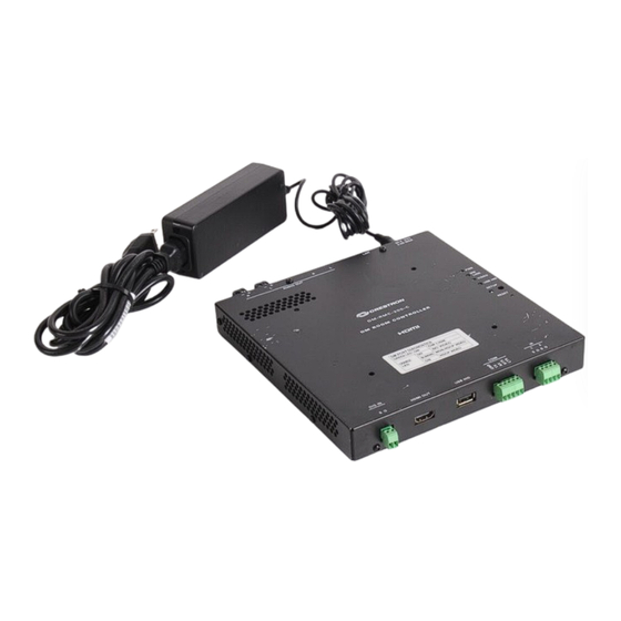
DM-RMC-200-S/DM-RMC-200-S2
DigitalMedia 8G™ Fiber Receiver and Room Controller
DO
Install the Device
The Crestron
DM-RMC-200-S and DM-RMC-200-S2 mount
®
onto a 2-gang electrical box using the included support
bracket. The support bracket provides a holder for the included
power pack.
Mounting the Device onto an Electrical Box
To mount the device onto an electrical box, do the following:
1. Attach the four included 6-32 x 1-1/4" standoffs to the
studs of the included support bracket.
2. Using the four included 6-32 x 3/4" combo truss head
screws, attach the included support bracket to the
electrical box.
3. Ground the device and then connect the proper cables to
the bottom of the unit.
Ground
RELAY:
To relay
controllable
devices
4. Using the four included 6-32 x 1/4" Phillips head screws,
attach the device to the standoffs.
Inserting the Power Pack
into the Power Pack Holder
To insert the power pack into the power pack holder, do the
following:
1. Slide the power pack into the power pack holder.
2. Using the included 6-32 x 1/2" Phillips pan head screw,
thread the screw through either of the two provided
screw holes to hold the power pack in place.
3. Bundle the excess cable of the power pack into a loop,
and then fasten the bundled cable to the power pack
holder by doing the following:
AUDIO OUT:
a. Insert one of the included tie wraps through one of
Ampli ed stereo
the tie wrap holes in the power pack holder.
audio output
b. Wrap the tie wrap around the bundled cable.
DIG IN:
Software
programmable
digital input
DO
Check the Box
QTY PRODUCT
1
Bracket, Support
2
Connector, 2-Pin
4
Connector, 2-Pin
2
Connector, 4-Pin
1
Connector, 5-Pin
1
Power Cord, 5' 10" (1.78 m)
1
Power Pack, 24 Vdc 2.5 A, 100-240 Vac
1
Screw, 6-32 x 1/2", Pan Head, Phillips
4
Screw, 6-32 x 1/4", Pan Head, Phillips
4
Screw, 6-32 x 3/4", Truss Head, Combo
4
Standoff, 06-32 x 1-1/4", 1/4" OD, Hex
2
Tie Wrap, Cable Tie, 15-1/2" x 1"
c. Repeat steps 3a and 3b if necessary using the other
Installation of the power pack in the holder appears as shown
below.
COLOR
PART NUM.
2047591
2003574
2003582
2003576
2003577
2042043
2045873
Black
2007238
Black
2007215
2009211
2007056
Black
2013608
included tie wrap and the remaining tie wrap hole in
the power pack holder.
Screw
hole*
Tie wrap
hole
Tie wrap
Screw
hole
hole*
*Use either screw hole for the included 6-32 x 1/2" Phillips
pan head screw.
Advertisement

Related Manuals for Crestron DigitalMedia 8G DM-RMC-200-S


Summary of Contents for Crestron DigitalMedia 8G DM-RMC-200-S
- Page 1 2003582 Connector, 4-Pin 2003576 Install the Device Connector, 5-Pin 2003577 The Crestron DM-RMC-200-S and DM-RMC-200-S2 mount ® Power Cord, 5' 10" (1.78 m) 2042043 onto a 2-gang electrical box using the included support Power Pack, 24 Vdc 2.5 A, 100-240 Vac 2045873 bracket.
- Page 2 FCC Rules. These limits are designed to provide reasonable protection against harmful interference when the equipment used in this document to refer to either the entities claiming the marks and names or their products. Crestron disclaims any proprietary interest in the marks and names of others. Crestron is is operated in a commercial environment.
Need help?
Do you have a question about the DigitalMedia 8G DM-RMC-200-S and is the answer not in the manual?
Questions and answers