Table of Contents

Related Manuals for STIEBEL ELTRON AWG 315 SR


Summary of Contents for STIEBEL ELTRON AWG 315 SR
- Page 1 INSTALLATION INSTALLAZIONE Wanddurchführung | Wall outlet | Traversée murale | Passaggio nella parete | Væggennemføring » AWG 315 GL » AWG 315 SR » AWG 315 L » AWG 560 H-GL » AWG 560 H-SR » AWG 560 V-GL » AWG 560 V-SR » AWG 560 L » AWG 600 L...
-
Page 2: Installation
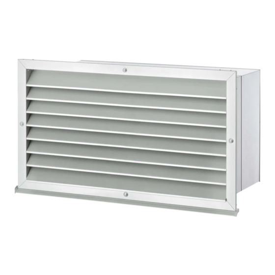
This symbol indicates that you have to do something. The action you need to take is described step by step. Standard delivery Relevant product AWG 315 GL / AWG 315 SR This document describes the installation of the following wall outlets: Wall outlet... - Page 3 INSTALLATION mounting AWG 560 V-GL / AWG 560 V-SR AWG 600 L 1 Weather grille 1 Grille to keep out small animals 2 Insert 2 Insert 3 Wall outlet 3 Wall outlet 4 Hose clip with tensioning closure 4 Hose clip with tensioning closure Also part of the standard delivery: AWG 315 L - Four self-tapping screws (4.2 x 32) to connect the insert...
- Page 4 Push the parts of the installation aid together at the cut-out points. 4.4.1 AWG 315 GL / AWG 315 SR / AWG 315 L: Affixing the f Position the installation aid in the wall outlet. insulating mat The installation aid stops the wall outlet becoming deformed as you carry out the next steps.
-
Page 5: Connecting The Air Hose
Sealing the weather grille all around 4.4.2 Securing the insert f Seal the gap between the building wall and weather grille, AWG 315 GL / AWG 315 SR / AWG 560 H-GL / e.g. using silicone. AWG 560 H-SR / AWG 560 V-GL / AWG 560 V-SR 4.6 Connecting the air hose f AWG 560 H-GL, AWG 560 H-SR, AWG 560 V-GL,... -
Page 6: Specification
INSTALLATION Specification f Seal the transition from the internal hose to the connector with the self-adhesive thermal insulation tape supplied. 1 Hose clamp f Secure the air hose to the connector using the hose clip. 1 Hose sleeve f Tighten the hose clip by turning the screw in the hose clip closure clockwise with a screwdriver. -
Page 7: Data Table
5.1.5 AWG 560 L max. air volume m³/h 1500 3500 3500 colour RAL 9006 RAL 9006 RAL 9006 AWG 315 SR AWG 560 H-SR AWG 560 V-SR 233836 233837 233838 Height Width Depth Weight Wall thickness 280 - 500 280 - 500 280 - 500 5.1.6 AWG 600 L... - Page 8 STIEBEL ELTRON GmbH & Co. KG tecalor GmbH Dr.-Stiebel-Str. 33 | 37603 Holzminden Lüchtringer Weg 3 | 37603 Holzminden Tel. 05531 702-0 | Fax 05531 702-480 Tel. 05531 99068-700 | Fax 05531 99068-712 info@stiebel-eltron.de info@tecalor.de www.stiebel-eltron.de www.tecalor.de 4 < A M H C M N = j b c e b g >...
Need help?
Do you have a question about the AWG 315 SR and is the answer not in the manual?
Questions and answers