Table of Contents
Advertisement
Quick Links
Advertisement
Table of Contents
Troubleshooting

Related Manuals for STIEBEL ELTRON LWZ 70 E


Summary of Contents for STIEBEL ELTRON LWZ 70 E
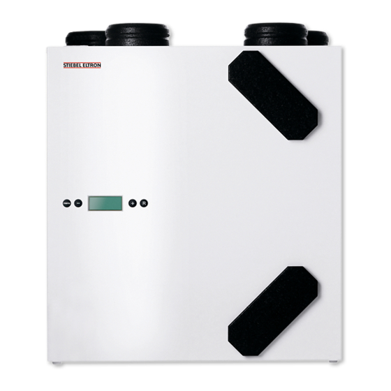
- Page 1 OPERATION AND INSTALLATION Central ventilation unit with heat recovery » LWZ 70 E...
-
Page 2: Table Of Contents
CONTENTS | SPECIAL INFORMATION SPECIAL INFORMATION Maintenance ������������������������������������������������ 16 Troubleshooting �������������������������������������������� 18 OPERATION Specification ������������������������������������������������ 19 General information �����������������������������������������3 15.1 Dimensions and connections ��������������������������������� 19 Safety instructions ����������������������������������������������� 3 15.2 Standard circuit ������������������������������������������������� 20 Other symbols in this documentation ����������������������� 3 15.3 Wiring diagram �������������������������������������������������... -
Page 3: General Information
OPERATION General information OPERATION Symbol Meaning Appliance disposal f This symbol indicates that you have to do something. The ac- General information tion you need to take is described step by step. The chapters "Special Information" and "Operation" are intended Units of measurement for both the user and qualified contractors. -
Page 4: General Safety Instructions
OPERATION Appliance description General safety instructions the supply air flow and the extract air flow is disrupted, thus pre- venting freezing. The supply air fan may also, for short periods, be switched OFF at very low outdoor temperatures. Preheating WARNING Injury the outdoor air by using an electric preheating coil or by means The appliance may be used by children aged 8 and up and of a geothermal heat exchanger, for example, can prevent this... -
Page 5: Switching The Appliance On
OPERATION Settings When the mains power is switched on, all available symbols are The appliance then runs according to the stage switch setting. If displayed for two seconds. The backlight is also switched on for no stage switch is connected, the appliance always runs in fan 60 seconds. -
Page 6: Standard Mode
OPERATION Settings 4.5.2 Indication of the air flow rate WARNING Electrocution Before working on the appliance, always isolate the appliance from the power supply by first switching the appliance off via the software and then unplugging it from the mains. Standard mode In standard mode, the display shows up to four different pieces of information (operating modes and values) simultaneously. -
Page 7: Maintenance, Cleaning And Care
OPERATION Maintenance, cleaning and care Maintenance, cleaning and care f Extract the supply air and extract air filters. Make a note of how the filters were fitted. Maintenance by the user is limited to filter cleaning or replacement required at certain intervals. Replacement filter Product desig- Part number... -
Page 8: Troubleshooting
OPERATION Troubleshooting To confirm that the filters have been reset, the text "FILTER" will If you cannot remedy the fault, notify your qualified contractor. flash briefly. Even if the message "FILTER" has not yet been dis- To facilitate and speed up your request, provide the number from played, you can reset the filter message. -
Page 9: Installation
INSTALLATION Safety INSTALLATION Simultaneous operation WARNING INJURY To prevent any flue gas escaping into the installation room, it is necessary to ensure that sufficient combustion Safety air is supplied or that the negative pressure in room where the stove is installed is not greater than 4 Pa. Only a qualified contractor should carry out installation, commis- Tested safety equipment must be installed to monitor the sioning, maintenance and repair of the appliance. -
Page 10: Appliance Description
INSTALLATION Appliance description Appliance description Minimum clearances Standard delivery The following are delivered with the appliance: - Wall mounting bracket set (2 mounting brackets, 3 protec- tive caps, 1 rubber strip, 2 rubber rings, 1 set of installation instructions) - PVC condensate drain (1x1.5” threaded plastic nut, 1 sealing ring, 1 PVC glued joint) - Approx. -
Page 11: Connecting The Condensate Drain
INSTALLATION Installation 10.3 Connecting air ducts During installation, ensure that no metal swarf enters the ductwork. However, should this still occur, you must remove this material, otherwise the fans may be damaged. External wall ducts f Place the rubber strips supplied on the rail mounted on the Supply outdoor air from a location where contamination (dust, wall. -
Page 12: Power Supply
INSTALLATION Commissioning 10.4 Power supply 11. Commissioning 11.1 Initial start-up WARNING Electrocution Carry out all electrical connection and installation work Setting the air flow rate in accordance with national and regional regulations. Output and energy consumption of the appliance depend on the WARNING Electrocution pressure drop in the duct system and the resistance of the filters. -
Page 13: Settings
INSTALLATION Settings 12. Settings Parameter change f Press menu. 12.1 Settings menu For optimum appliance function, you can change parameters used to adapt the appliance to the actual installation. Some parameter settings such as the air flow rates have been set out in the technical details appertaining your individual building. -
Page 14: Read-Out Menu
INSTALLATION Settings 12.1.2 List of parameters in the settings menu Parameter Description Unit Factory Setting range Step Display text and setting size symbols Air flow rate of stage 50: Moisture protection ventilation Air flow rate of stage 1 50 - 180 Air flow rate of stage 2 50 - 180 Air flow rate of stage 3... -
Page 15: Service Menu
INSTALLATION Settings Indication "No fault message" Current fault message (fault symbol on the display) f Press R twice to return to standard mode. For fault messages with a cause that has not yet been eliminated, If no key is pressed for 5 minutes, the appliance returns automat- the fault symbol (spanner) appears. -
Page 16: Restoring Factory Settings
INSTALLATION Maintenance 12.4 Restoring factory settings It is possible to reset all changed settings simultaneously to factory settings. All changed settings revert back to their factory default settings; all message/fault codes are also deleted from the service menu. f Remove the display. f Press plus and minus simultaneously and hold down for 10 seconds. - Page 17 INSTALLATION Maintenance f Reconnect the fan cables to the PCB. Observe the label in the appliance to establish the correct position for the plug-in connections. f Slide the insert with the control PCB into the appliance. f Install the display. f Reconnect all cables disconnected before cleaning, to their original position.
-
Page 18: Troubleshooting
INSTALLATION Troubleshooting 14. Troubleshooting Correct microswitch setting Fault Block- Cause Appliance be- Measure code haviour fault E104 The extract air Both fans are Isolate the appliance fan is faulty. switched off. The from the power sup- preheating coil, if ply. Replace the ex- present, is switched tract air fan. -
Page 19: Specification
INSTALLATION Specification 15. Specification 15.1 Dimensions and connections LWZ 70 E Entry electrical cables Condensate drain Diameter Outdoor air Nominal diameter DN 125 g04 Exhaust air Nominal diameter DN 125 Extract air Nominal diameter DN 125 g06 inrushing air Nominal diameter DN 125 www.stiebel-eltron.com LWZ 70 E |... -
Page 20: Standard Circuit
INSTALLATION Specification 15.2 Standard circuit ZLWZ 4S 3-Stufen-Schalter Lüftungsgerät 6 x 0,5 mm² max. 30 m 1/N/PE 230V ~50Hz Differenzdruckcontroller für Feuerstätten 3-Stufen-Schalter 3-stage switch ZLWZ 4S 4-stage switch Air quality sensor Remote control Lüftungsgerät Ventilation unit Ofen Stove Raum Room Druckanschluss Pressure connection... -
Page 21: Wiring Diagram
INSTALLATION Specification 15.3 Wiring diagram 3-stage switch, 4-stage switch, air quality sensor FEQ or remote control FEZ (see chapter "Specification / Standard circuit") External preheating coil (optional) Outside temperature sensor Room temperature sensor Service connection Wire no. 1 Wire no. 2 www.stiebel-eltron.com LWZ 70 E |... -
Page 22: Fan Diagram
INSTALLATION Specification 15.4 Fan diagram 0,62 0,59 0,53 0,51 0,49 0,43 0,40 0,46 0,45 0,40 0,40 0,37 0,37 0,34 0,32 0,32 0,29 0,28 0,28 0,27 0,26 Air flow rate [m³/h] Average value, static pressure [Pa] Example: system curve with low pressure drop Example: system curve with average pressure drop Example: system curve with higher pressure drop Specific power consumption of both fans [Wh/m³]... -
Page 23: Data Table
INSTALLATION | GUARANTEE | ENVIRONMENT AND RECYCLING Specification 15.5 Data table LWZ 70 E 233851 Sound data Sound power level (EN 12102) dB(A) Energy data Energy efficiency class Electrical data Rated voltage Max. current drawn 1.48 Power consumption without preheater coil 1.48 Phases 1/N/PE Frequency... - Page 24 Deutschland Verkauf Tel. 05531 702-110 | Fax 05531 702-95108 | info-center@stiebel-eltron.de STIEBEL ELTRON GmbH & Co. KG Kundendienst Tel. 05531 702-111 | Fax 05531 702-95890 | kundendienst@stiebel-eltron.de Dr.-Stiebel-Straße 33 | 37603 Holzminden Ersatzteilverkauf Tel. 05531 702-120 | Fax 05531 702-95335 | ersatzteile@stiebel-eltron.de Tel.
Need help?
Do you have a question about the LWZ 70 E and is the answer not in the manual?
Questions and answers