Table of Contents
Advertisement
Available languages
Available languages
Quick Links
D
Einbau- und Betriebsanleitung für Fachpersonal............................................................2
GB
Installation and operating instructions for the specialised installer ................................5
F
Notice d'installation et d'utilisation pour le professionnels.............................................8
E
Instrucciones de instalación y operación para el instalador especializado..................11
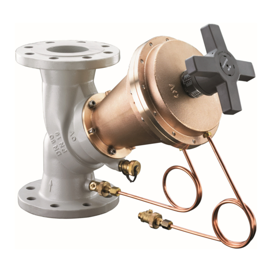
„Hydromat DFC"
Advertisement
Table of Contents

Related Manuals for oventrop Hydromat DFC


Summary of Contents for oventrop Hydromat DFC
- Page 1 „Hydromat DFC” Einbau- und Betriebsanleitung für Fachpersonal............2 Installation and operating instructions for the specialised installer ........5 Notice d’installation et d’utilisation pour le professionnels..........8 Instrucciones de instalación y operación para el instalador especializado....11...
- Page 2 Die Betriebssicherheit ist nur bei bestimmungsgemäßer durch geschultes Fachpersonal durchgeführt werden Verwendung des Ventils gewährleistet. Die Einbau- und Betriebsanleitung sowie alle mitgeltenden Oventrop Differenzdruckregler „Hydromat DFC“ sind zum Unterlagen sind an den Anlagenbetreiber weiterzugeben Einbau in Heiz- und Kühlsystemen mit geschlossenem Wasserkreislauf zur automatischen Differenzdruckregelung Inhalt: (hydraulischer Abgleich) bestimmt.
- Page 3 Bevor der Regler in die Rohrleitung ein- gesetzt wird, ist diese gründlich zu spülen. Es empfiehlt (Art.-Nr. 106 49 ..) sich der Einbau eines Oventrop Schmutzfängers. Die Im- max. Betriebsdruck p 16 bar (PN 16) pulsleitung sollte stets oberhalb bis waagerecht, nicht je- max.
- Page 4 Fenster der Umfangsskala gut sicht- 7.3 Voreinstellung bar ist. Dann das Handrad wieder auf die Ventilspindel Der Sollwert des Oventrop Differenzdruckreglers kann stu- aufdrücken und befestigen. Anschließend die Abdeck- fenlos von 200 und 1000 mbar oder 400 bis 1800 mbar kappe aufdrücken.
-
Page 5: Table Of Contents
The installation and operating instructions, as well as ot- Oventrop differential pressure regulators “Hydromat DFC“ her valid documents must remain with the user of the are installed in heating and cooling systems with closed... -
Page 6: Technical Data
200 up to 1000 mbar 400 up to 1800 mbar “Hydromat DFC” 106 46 51 106 47/49 51 Illustr. 6.1 “Hydromat DFC”, installation in the return pipe 106 46 52 106 47/49 52 After installation, the handwheel and the measuring con-... -
Page 7: Operation
Next, without altering the setting, adjust the position of 7.3 Presetting the handwheel so that the indicator window of the peri- The nominal value of the Oventrop differential pressure re- pheral scale is clearly visible. Finally, refit the handwheel gulator is infinitely adjustable between 200 and 1000 mbar to the valve stem, tighten the screw and replace the cover or 400 and 1800 mbar. - Page 8 Robinetterie «haut de gamme» + Systèmes Régulateur de pression différentielle «Hydromat DFC» Notice d’installation et d’utilisation pour le professionnels Lire intégralement la notice d’installation et d’utilisation 2 Consignes de sécurité avant le montage du régulateur de pression différentielle 2.1 Utilisation conforme Le montage, la mise en route, le service et l’entretien ne...
- Page 9 106 46 51 106 47/49 51 «Hydromat DFC» 106 46 52 106 47/49 52 Fig. 6.1 «Hydromat DFC», montage sur le retour 106 46 53 106 47/49 53 110 La poignée manuelle et les raccordements de mesure 106 46 54 106 47/49 54 145 doivent être facilement accessibles après le montage.
- Page 10 La valeur de consigne du régulateur de pression différen- sur la tige du robinet et la fixer. Remettre le capot. tielle Oventrop est à réglage progressif entre 200 et 1000 mbars ou 400 et 1800 mbars. La valeur désirée peut être 7.6 Blocage de la poignée manuelle...
- Page 11 Los reguladores de presión diferencial “Hydromat DFC” ¡Las instrucciones de instalación y funcionamiento, así de Oventrop se instalan en sistemas de calefacción y refri- como cualquier otra documentación válida, deben per- geración con circuitos cerrados de calefacción para una manecer con el usuario del sistema regulación automática de la presión diferencial (equilibrado...
- Page 12 – Orificio circular de las bridas según ANSI 150 ésta debe ser lavada a fondo. Se recomienda la instalación (art. nº 106 49 ..) de un filtro tipo “Y” de Oventrop. El capilar debe montarse máx. presión de funcionamiento p 16 bar (PN 16) por encima o en horizontal respecto a la tubería de ida,...
- Page 13 El valor nominal del regulador de presión diferencial de pón. Oventrop puede ajustarse en todos los puntos entre 200 7.6 Bloqueo del volante y 1000 mbar ó 400 y 1800 mbar.
-
Page 14: Design Of The Differential Pressure Regulator
11 Auslegung des Differenzdruckreglers Design of the differential pressure regulator Dimensionnement du régulateur de pression différentielle Diseño del regulador de presión diferencial Der empfohlene Anwendungsbereich wird durch den minimalen Durchfluss (qm ) und dem maximalen Durch- min. fluss (qm ) bestimmt. max. - Page 15 DN 65: kvs = 52; z-Wert/z-value/Valeur z/Valor z = 0.45 Einbaubeispiel/Installation example/Exem- ple de montage/Ejemplo de instalación Vorlauf Flow Sollwert ∆p Aller Nominal value ∆p Valeur de consigne ∆p Valor nominal ∆p ∆p de ajuste ∆p Rücklauf Return Retour Retorne Massenstrom qm/Flow rate qm/Débit qm/Caudal qm [x 1000 kg/h] Geringste P-Abweichung bei qm nom.
- Page 16 Eine Übersicht der weltweiten Ansprechpartner finden Sie unter www.oventrop.de. For an overview of our global presence visit www.oventrop.com. Vous trouverez une vue d’ensemble des interlocuteurs dans le monde entier sur www.oventrop.com. Para una visión general de nuestra presencia en el mundo visite www.oventrop.com.
Need help?
Do you have a question about the Hydromat DFC and is the answer not in the manual?
Questions and answers