Table of Contents
Advertisement
Available languages
Available languages
Quick Links
Advertisement
Chapters
Table of Contents

Related Manuals for oventrop Unibox E RTL


Summary of Contents for oventrop Unibox E RTL
- Page 1 Premium Armaturen + Systeme Rücklauftemperaturregelung „Unibox E RTL“ Betriebsanleitung Return flow temperature control "Unibox ERTL" Operating instructions Régulation de la température de retour « Unibox ERTL » Notice d'utilisation...
-
Page 3: Table Of Contents
Technische Daten ......................9 Zubehör und Ersatzteile ..................9 Transport und Lagerung ..................9 Montage ......................9 Allgemeine Montagehinweise .................... 9 Montage „Unibox E RTL“ ....................10 Inbetriebnahme ....................11 Füllen, Entlüften und Dichtheit prüfen ................11 Vorarbeiten Funktionsheizen ................... 11 Funktionsheizen ......................12 Abdeckplatte aufsetzen .................... - Page 4 Inhaltsverzeichnis Unibox E RTL Betrieb ......................12 Störungen beheben ..................13 Instandhaltung ....................14 Entsorgung .....................14 Anhang ......................15 12.1 Häufige Fragen ........................ 15 Abbildungsverzeichnis ..................18 Index ........................19 Glossar ......................20 102273180-V02.06.2019...
-
Page 5: Allgemeine Angaben
Der Lieferumfang umfasst: beschäftigten Personen bestimmt. • „Unibox E RTL“ mit Bauschutzabdeckung 1.5 Konformitätserklärung • Abdeckplatte Hiermit erklärt die Oventrop GmbH & Co. KG, • Winkel dass dieses Produkt in Übereinstimmung mit • Betriebsanleitung den grundlegenden Anforderungen und den einschlägigen Bestimmungen der betreffenden EU-Richtlinien hergestellt wurde. -
Page 6: Sicherheitsbezogene Informationen
Verwendung des Produktes gewähr- wird. leistet. Die „Unibox E RTL“ begrenzt die Medientem- 2.5 Sicherheitshinweise peratur eines Radiatorheizkreises und nutzt sie zur Temperierung von Boden- und Wandflä- Dieses Produkt ist so konstruiert, dass es chen in einzelnen Räumen. -
Page 7: Verletzungsgefahr Bei Unsachgemäßer Arbeit
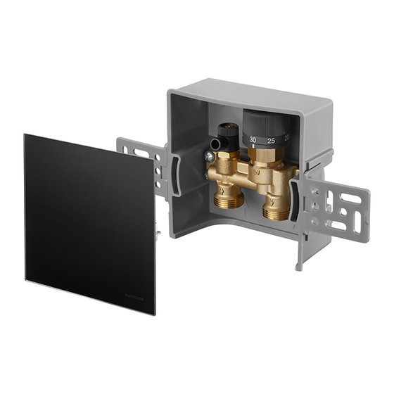
Führen Sie Arbeiten nur bei drucklosem Produkt aus. f Lassen Sie das Produkt vor Arbeiten abkühlen. f Prüfen Sie nach Arbeiten das Produkt auf Abb. 2: Aufbau „Unibox E RTL“ Dichtheit. f Decken Sie Entlüftungsöffnungen gegebe- Wandeinbaukasten nenfalls mit einem Tuch ab. -
Page 8: Funktionsbeschreibung
Technische Beschreibung Unibox E RTL 3.3 Funktionsbeschreibung Die „Unibox E RTL“ dient zur Begrenzung der Rücklauftemperatur einer Flächentemperie- rung. Die Einbauposition der „Unibox E RTL“ ist so zu wählen, dass zunächst der Heizkreis und anschließend das Ventil der „Unibox E RTL“... -
Page 9: Technische Daten
Montagekanal 1022652 Vor der Montage sollten Sie folgendes beach- 1022653 ten: Formschacht 1022650 • Die Unterkante der „Unibox E RTL“ muss Duo-Anschlussstück 1022655 mindestens 20 cm über dem fertigen Fuß- boden liegen. Schutzrohr (siehe Abb. 5 auf 1501184 Seite 10) •... -
Page 10: Montage „Unibox E Rtl
Montage Unibox E RTL 6.2 Montage „Unibox E RTL“ ACHTUNG Sachschaden durch Schmier- Die „Unibox E RTL“ muss sich mittel! immer am Ende des Flächentempe- rierungskreises befinden (siehe 3.3 Dichtungen können durch die Verwen- auf Seite 8). dung von Fetten oder Ölen zerstört werden. -
Page 11: Inbetriebnahme
Unibox E RTL Inbetriebnahme 4. Nutzen Sie die beiliegenden Winkel (siehe 1.2 auf Seite 5) um die „Unibox E RTL“ im Formschacht auszurichten und zu befestigen. Abb. 8: Bauabdeckung aufsetzen 7.2 Vorarbeiten Funktionsheizen Führen Sie das Funktionsheizen durch um die ordnungsgemäße Funktion der Flächentempe-... -
Page 12: Funktionsheizen
Betrieb Unibox E RTL 7.3 Funktionsheizen Gehen Sie beim Funktionsheizen wie folgt vor: 1. Öffnen Sie das Ventil vollständig durch betätigung des Handrads (siehe 3.4 auf Seite 8). Regeln Sie die Vorlauftempera- tur nun über die Steuerung des Wärme erzeugers. -
Page 13: Störungen Beheben
Unibox E RTL Störungen beheben Störungen beheben STÖRUNG URSACHE BEHEBUNG Die Flächentemperierung wird Die „Unibox E RTL“ ist im Die „Unibox E RTL“ muss nicht warm. Vorlauf eingebaut. von einer Rücklauftempe- raturbegrenzung in eine Einzelraumtemperaturregelung („Unibox T“) umgebaut wer- den. Verwenden Sie dafür den Umrüstsatz „Unibox T“. -
Page 14: Instandhaltung
Instandhaltung Unibox E RTL 10. Instandhaltung Prüfen Sie die Dichtheit und Funktion der Ar- matur und ihrer Verbindungsstellen im Rahmen der Anlagenwartung regelmäßig. 11. Entsorgung ACHTUNG Verschmutzungsgefahr für die Umwelt! Nicht fachgerechte Entsorgung (z. B. im Hausmüll) kann zu Umweltschäden führen. -
Page 15: Anhang
Abb. 11: Anschlussschema zwei Heizkreise mit „Duo-An- schlussstück“ Wie viel m² Flächentemperie- Pro „Unibox E RTL“ können Sie ca. 20 m² Fläche anschließen. rung kann ich an die „Unibox Die Rohrlänge darf max. 100 m betragen bei einem 17er Rohr. -
Page 16: Abb. 12: Anschluss Mit Bypass-Ventil Und Heizkörperverschraubung Mit Bypass
Anhang Unibox E RTL FRAGE ANTWORT Kann ich die „Unibox E RTL“ Die „Unibox E RTL“ ist für Einrohrheizungsanlagen geeignet. auch bei einer Einrohrheizung Möglichkeit 1: verwenden? Abb. 12: Anschluss mit Bypass-Ventil und Heizkörperver- schraubung mit Bypass Bypass-Ventil Heizkörperverschraubung mit Bypass - Der Volumenstrom und Druckverlust können sich erhöhen. -
Page 17: Abb. 14: Anschluss Mit „Unibox Rla
Unibox E RTL Anhang FRAGE ANTWORT - Der Volumenstrom und Druckverlust können sich erhöhen. - Beachten Sie die Druckverlust und Geräuschkennlinie der Heizkörperarmaturen. - Regulieren Sie das Bypass-Ventil so ein, dass genug Wasser durch die Flächentemperierung fließt. - Bei geschlossenem Ventil dürfen am Heizkörper keine Ge- räusche entstehen. -
Page 18: Abbildungsverzeichnis
Abbildungsverzeichnis Unibox E RTL 13. Abbildungsverzeichnis Seite Abb. 1: Bauabdeckung auf „Unibox ERTL“ ................... 5 Abb. 2: Aufbau „Unibox ERTL“ ...................... 7 Abb. 3: Maße in mm ........................7 Abb. 4: Handrad ..........................8 Abb. 5: Einbauquerschnitt ......................10 Abb. 6: Anschluss ........................10 Abb. -
Page 19: Index
Unibox E RTL Index 14. Index Seite Bypass-Ventil .......................... 16, 17 Duo-Anschlussstück ........................15 Einrohrheizung ..........................16 Einzelraumtemperaturregelung ..................... 13 Kontakt ............................5 Lieferumfang ........................... 5 Sanitär-, Heizungs- und Klimatechnik-Fachhandwerker ..............6 Schmiermittel ..........................10 Technische Daten ..........................9 Zubehör ............................9... -
Page 20: Glossar
Glossar Unibox E RTL 15. Glossar Bypass-Ventil Ein Bypass-Ventil ist ein Absperr- oder Drosselventil, das eingesetzt wird um ein anderes Bauteil zu umgehen. Das Bypassventil ist in einer Leitung verbaut, welche das andere Bauteil umgeht. Mit dem Einbau dieses Ventils werden verschiedene Ziele verfolgt: •... - Page 23 Accessories and spare parts ................29 Transport and storage ...................29 Installation ......................29 General installation advice ....................29 "Unibox E RTL" installation ..................... 30 Commissioning ....................31 Filling, bleeding and leak testing ..................31 Preliminary work for incremental heating test ..............31 Incremental heating test ....................32 Positioning the cover plate ....................
- Page 24 Contents Unibox E RTL Operation ......................32 Troubleshooting .....................33 Maintenance ....................34 Disposal ......................34 Appendix ......................35 12.1 FAQs ..........................35 Illustration index .....................38 Index ........................39 Glossary ......................40 102273180-V02.06.2019...
-
Page 25: General Information
E RTL" is protected by a protec- tion cover made of cardboard (see Highlights important information Illustr. 1 on page 25). and further explanations. Action required • List Fixed order. Steps 1 to X. Result of action Illustr. 1: Protection cover on "Unibox E RTL" 102273180-V02.06.2019... -
Page 26: Safety-Related Information
Safety in operation is only guaranteed if the damage to property if not avoided. product is used correctly. "Unibox E RTL" limits the media temperature of a radiator heating circuit and uses it to control the temperature on floor and wall surfaces in 2.5 Safety notes... -
Page 27: Risk Of Injury In Case Of Improper Work
Only carry out work when the product is depressurised. f Allow the product to cool down before working on it. Illustr. 2: "Unibox E RTL" construction f Check that the product is not leaking after work is complete. Wall installation cabinet f If necessary, cover the vent holes with a cloth as appropriate. -
Page 28: Functional Description
"Unibox E RTL" valve. The heating medium cools down from entering the heating surface up to "Unibox E RTL". The valve with integrated return temperature limiter automati- Illustr. 4: Handwheel cally controls the flow. -
Page 29: Technical Data
Forming shaft 1022650 flooring. Duo connector 1022655 • The front edge of "Unibox E RTL" must be at the same level as the completed wall. Protective pipe (see Illustr. 5 on 1501184 page 30) If the wall has not been completed, note the design specified by plaster and tiles. -
Page 30: Unibox E Rtl" Installation
3. Remove the valve’s protection cover and Screed the front cover of the forming shaft (you Protective pipe (separate accessory) must reposition the protection and front cover following commissioning) and insert "Unibox E RTL" into the forming shaft. 102273180-V02.06.2019... -
Page 31: Commissioning
Illustr. 8: Positioning the protection cover 7.2 Preliminary work for incremental heating test Illustr. 7: "Unibox E RTL" with brackets Carry out an incremental heating test to check the correct function of the surface temperature 5. Connect the surface temperature balance balance. -
Page 32: Incremental Heating Test
7.4 Positioning the cover plate 1. After having completed all building work, remove the "Unibox E RTL" protection cover. 2. Position the cover plate on "Unibox E RTL". Illustr. 9: Positioning the cover plate Operation Adjust the medium temperature of the surface temperature balance circuit using the hand- wheel (see 3.4 on page 28). -
Page 33: Troubleshooting
Unibox E RTL Troubleshooting Troubleshooting MALFUNCTION CAUSE REMEDY Surface temperature balance "Unibox E RTL" has been Convert "Unibox E RTL" from does not reach hot tempera- installed in the supply. a return flow temperature tures. limiter to an individual room temperature control ("Unibox... -
Page 34: Maintenance
Maintenance Unibox E RTL 10. Maintenance Regularly check the integrity and function of the valves and fittings as well as their connec- tion points as part of system maintenance. 11. Disposal NOTICE Risk of environmental pollution! Incorrect disposal (for instance with do- mestic waste) may lead to environmen- tal damage. -
Page 35: Appendix
Is it possible to connect two Yes, use a "duo connector" to connect two heating circuits with heating circuits to "Unibox E the same size to one "Unibox E RTL". Each surface tempera- RTL"? ture balance circuit can feature pipes with a maximum length of 80 m, providing you use size 16/17 pipes. - Page 36 Appendix Unibox E RTL QUESTION RESPONSE Can I also use "Unibox E RTL" "Unibox E RTL" is suitable for one pipe heating. for one pipe heating? Option 1: Illustr. 12: Connection with bypass valve and radiator screw connection with bypass...
- Page 37 Unibox E RTL Appendix QUESTION RESPONSE - Volume flow and pressure loss may increase. - Note the pressure loss and noise characteristic of the radi- ator fittings. - Configure the bypass valve so that a sufficient amount of water flows through the system for surface temperature balance.
-
Page 38: Illustration Index
Illustration index Unibox E RTL 13. Illustration index Page Illustr. 1: Protection cover on "Unibox ERTL"................27 Illustr. 2: "Unibox ERTL" construction ................... 29 Illustr. 3: Dimensions in mm ......................29 Illustr. 4: Handwheel ........................30 Illustr. 5: Installation cross section....................32 Illustr. -
Page 39: Index
Unibox E RTL Index 14. Index Page Accessories ........................... 31 Bypass valve ........................... 38, 39 Contact ............................27 Duo connector ..........................37 Extent of supply ..........................27 Individual room temperature control ..................... 35 Lubricants ............................. 32 One pipe heating ........................... 38 Sanitary, heating and air-conditioning specialists ................. -
Page 40: Glossary
Glossary Unibox E RTL 15. Glossary Bypass valve A bypass valve is a shutoff or throttling valve that is used to bypass another component. The bypass valve is installed in a pipe that bypasses the other component. Installing such a valve has the following purpose: •... - Page 43 Accessoires et pièces de rechange .............49 Transport et stockage ...................49 Montage ......................49 Instructions générales de montage ................. 49 Montage « Unibox E RTL » ....................50 Mise en service ....................51 Remplissage, purge et test d'étanchéité ................. 51 Préparation de la mise en chauffe ................... 51 Mise en chauffe .......................
- Page 44 Sommaire Unibox E RTL Exploitation .....................52 Correction des dysfonctionnements ............53 Entretien ......................54 Traitement des déchets .................54 Annexe ......................55 12.1 Questions fréquentes ...................... 55 Liste des figures .....................58 Index ........................59 Glossaire ......................60 102273180-V02.06.2019...
-
Page 45: Généralités
Fourniture : 1.5 Déclaration de conformité • « Unibox E RTL » avec protection pour le montage Par la présente, la société Oventrop GmbH & • Plaque de recouvrement Co. KG déclare que ce produit est en confor- mité... -
Page 46: Informations Relatives À La Sécurité
Signale une situation susceptible d'en- traîner des dégâts matériels si elle n'est L'« Unibox E RTL » limite la température du pas évitée. fluide d'un circuit de chauffage de radiateur et l'utilise pour réguler la température des sur- faces au sol et au mur dans chaque pièce. -
Page 47: Risque De Blessure Lié À Des Travaux Non Conformes
N'effectuer les interventions que lorsque le produit n'est plus sous pression. f Laisser le produit refroidir avant de débuter toute intervention. Fig. 2: Configuration de l'« Unibox E RTL » f Contrôler l'étanchéité du produit au terme des interventions. Boîtier de montage mural f Au besoin, recouvrir les ouvertures de ventilation avec un chiffon. -
Page 48: Description Du Fonctionnement
L'« Unibox E RTL » sert à limiter la tempéra- ture de retour d'un système de régulation de température de surfaces. Choisir la position de montage de l'« Unibox E RTL » pour que le circuit de chauffage soit traversé en premier et le robinet de l'« Unibox E RTL » ensuite. Le liquide chauffant se refroidit entre l'entrée dans... -
Page 49: Données Techniques
Tenir compte des instructions suivantes avant Gaine encastrable 1022650 de procéder au montage : Pièce de raccordement à 1022655 • Le bord inférieur de l'« Unibox E RTL » doit double sortie se situer au minimum 20 cm au-dessus du Tube de protection (voir Fig. 5 1501184 sol fini. -
Page 50: Montage " Unibox E Rtl
3. Retirer le capot de construction du robinet Tube de protection (accessoire fourni et le capot frontal de la gaine encastrable séparément) (remettre les deux protections après la mise en service) et insérer l'« Unibox E RTL » dans la gaine encastrable. 102273180-V02.06.2019... -
Page 51: Mise En Service
Réaliser la mise en chauffe des 6. Créer une conduite de raccordement à chapes de ciment et de sul- partir de l'« Unibox E RTL » vers le retour fate de calcium selon la norme de l'installation de chauffage bitube. DIN EN 1264-4. -
Page 52: Mise En Chauffe
Exploitation Unibox E RTL 7.3 Mise en chauffe Procédure de mise en chauffe : 1. Ouvrir complètement le robinet en tournant la poignée manuelle (voir 3.4 page 48). La température de départ doit être désormais réglée par la commande du générateur de chaleur. -
Page 53: Correction Des Dysfonctionnements
DYSFONCTIONNEMENT CAUSE MESURE DE CORREC- TION Le système de régulation de L'« Unibox E RTL » est mon- L'« Unibox E RTL » doit être température de surfaces ne tée sur l'aller. convertie d'un dispositif géné- chauffe pas. ral de limitation de tempéra- ture de retour en dispositif de régulation de température par... -
Page 54: Entretien
Entretien Unibox E RTL 10. Entretien Vérifier régulièrement l'étanchéité et le fonc- tionnement du distributeur/collecteur en acier inoxydable « Multidis SFQ » et des points de raccordement lors de l'entretien de l'installa- tion. 11. Traitement des déchets AVIS Risque de pollution ! Une élimination non conforme (par ex. -
Page 55: Annexe
Deux circuits de chauffage Oui, deux circuits de chauffage de la même taille peuvent être peuvent-ils être raccordés à raccordés à une même « Unibox E RTL » avec une « pièce de une même « Unibox E RTL » ? raccordement à double sortie ». Chaque circuit de régulation de température de surfaces peut avoir jusqu'à... - Page 56 Annexe Unibox E RTL QUESTION RÉPONSE Est-il possible d'utiliser L'« Unibox E RTL » est compatible avec les installations de l'« Unibox E RTL » avec un chauffage monotube. chauffage monotube ? Configuration 1 : Fig. 12: Raccordement avec robinet bypass et raccord de radiateur avec bypass...
- Page 57 Unibox E RTL Annexe QUESTION RÉPONSE - Le débit et la perte de charge peuvent augmenter. - Respecter les courbes caractéristiques de la perte de charge et des bruits de la robinetterie de radiateur. - Réajuster le robinet bypass pour que suffisamment d'eau traverse le système de régulation de température de sur-...
-
Page 58: Liste Des Figures
Liste des figures Unibox E RTL 13. Liste des figures Page Fig. 1: Capot de construction de l'« Unibox ERTL » ..............45 Fig. 2: Configuration de l'« Unibox ERTL » ..................47 Fig. 3: Dimensions en mm ......................47 Fig. 4: Poignée manuelle ....................... 48 Fig. -
Page 59: Index
Unibox E RTL Index 14. Index Page Accessoires ........................... 49 Chauffage monotube ........................56 Contact ............................45 Données techniques ........................49 Fourniture ............................45 Lubrifiants ............................. 50 Pièce de raccordement à double sortie ..................55 Professionnel du sanitaire, du chauffage et de la climatisation ............ 46 Régulation de température par pièce.................... -
Page 60: Glossaire
Glossaire Unibox E RTL 15. Glossaire Robinet bypass Un robinet bypass est une vanne d'arrêt ou d'étranglement utilisée pour contourner un autre composant. Le robinet bypass est intégré à une conduite contournant l'autre composant. Ce robinet a plusieurs objectifs : • Garantir un débit minimal •... - Page 64 OVENTROP GmbH & Co. KG Paul-Oventrop-Straße 1 D-59939 Olsberg Telefon +49 (0) 29 62 82-0 Telefax +49 (0) 29 62 82-400 E-Mail mail@oventrop.de www.oventrop.com Internet 102273180 V02.06.2019...
Need help?
Do you have a question about the Unibox E RTL and is the answer not in the manual?
Questions and answers