
Related Manuals for Clarke GRH15


Summary of Contents for Clarke GRH15
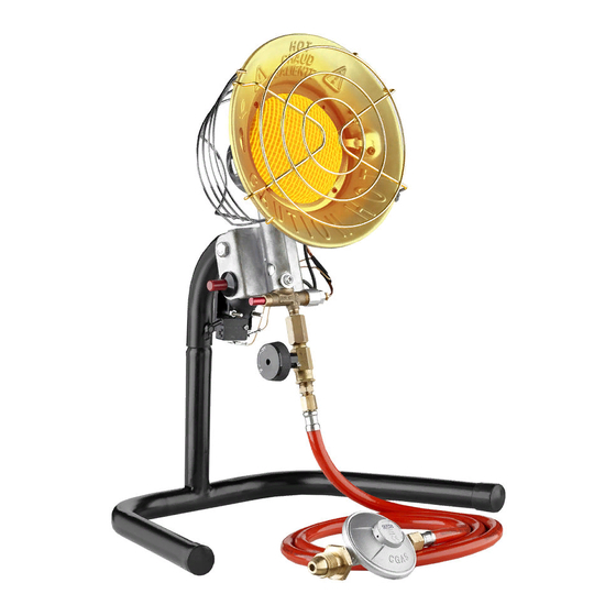
- Page 1 PORTABLE GAS RADIANT HEATER MODEL NO: GRH15 PART NO: 6920018 OPERATION & MAINTENANCE INSTRUCTIONS ORIGINAL INSTRUCTIONS GC1019 - ISS 1...
- Page 2 INTRODUCTION Thank you for purchasing this CLARKE heater. This portable gas radiant heater is designed to give safe, efficient and reliable operation and is for use with Propane Gas only. Propane gas bottles are readily available from builders merchants or gas suppliers.
-
Page 3: General Safety Precautions
GENERAL SAFETY PRECAUTIONS 10. This heater is for indoor use only in Read and ensure you fully well ventilated areas. understand the following precautions and the hazards associated with this 11. If at any time, gas odour is type of equipment. detected, IMMEDIATELY STOP 1. -
Page 4: Fresh Air Requirements
FRESH AIR REQUIREMENTS • DO NOT use in unventilated areas. • The flow of combustion and ventilation air must not be obstructed. WARNING: PROVIDE AT LEAST A 3FT OPENING OF FRESH, OUTSIDE AIR WHILST USING THIS HEATER. IF FRESH OUTSIDE AIR VENTILATION IS NOT PROVIDED, CARBON MONOXIDE POISONING CAN OCCUR. -
Page 5: If You Smell Gas
IF YOU SMELL GAS NO ODOUR DETECTED Liquid Propane gas has a man-made odourant added specifically for detection 1. Some people cannot smell the odour of gas leaks. added to propane (LP). You must If a leak occurs you should be able to determine if you can smell the smell the gas. -
Page 6: Gas System
FEATURES OF THE GRH15 Understanding the basic operation of the heater will reinforce the need to maintain it in top condition at all times whilst always observing the safety precautions. The heater comprises of three basic systems: 1. The gas system. -
Page 7: Installation
Remove the heater from the carton and remove all protective material used for shipment. Check the heater for possible shipping damage. Should any damage be apparent, please notify your CLARKE dealer immediately. ASSEMBLING THE SUPPORT STAND 1. Connect the stand base section to the upper part and secure with the wing nut supplied. -
Page 8: Gas Connection
GAS CONNECTION WARNING: PROPANE GAS CYLINDERS MUST BE USED AND STORED IN ACCORDANCE WITH THE ‘HIGHLY FLAMMABLE LIQUIDS AND LIQUEFIED PETROLEUM GASES REGULATIONS 1972. WARNING: IF YOU DO NOT FOLLOW THESE INSTRUCTIONS EXACTLY, A FIRE OR EXPLOSION MAY RESULT CAUSING PROPERTY DAMAGE, PERSONAL INJURY OR LOSS OF LIFE. - Page 9 4. Place the regulator on the cylinder connection and hand tighten by turning anti-clockwise. 5. Tighten firmly using a gas spanner (or an adjustable spanner), continuing in an anti-clockwise direction. 6. Simply turn the valve hand wheel anti-clockwise when you need to start the flow of gas.
-
Page 10: Operation
OPERATION WARNING: BEFORE STARTING THE HEATER YOU MUST ENSURE THAT THE MINIMUM VENTILATION REQUIREMENTS ARE OBSERVED TO AVOID THE RISK OF CARBON MONOXIDE POISONING. WARNING: THIS HEATER WILL BE HOT DURING NORMAL OPERATION. AVOID PHYSICAL CONTACT. DO NOT ALLOW CLOTHING OR OTHER COMBUSTIBLE MATERIALS TO TOUCH THE HEATER. - Page 11 WARNING: DO NOT FACE THE HEATER ELEMENT WHEN STARTING - ALWAYS STAND TO ONE SIDE. NOTE: If a new gas cylinder has been connected, it may take time for the gas line to be purged of air. Press the Piezo electric button every 10-15 seconds until it ignites.
-
Page 12: Troubleshooting
TROUBLESHOOTING Fault Cause Remedy Burner fails to light 1.Gas supply valve 1.Open gas supply valve closed. slowly 2.Excess gas flow 2.Close propane supply valve at propane tank and re- open slowly. 3.Piezo ignition not 3.Check wire lead for sparking. damage. Replace igniter assembly. -
Page 13: Cleaning And Maintenance
5. If the hose shows evidence of excessive abrasion or wear or if the hose is cut it must be replaced prior to the heater being put into operation. The replacement hose assembly shall be as supplied by CLARKE International. 6. The heater, including hose and regulator assembly, must be inspected at least annually by a qualified service person. -
Page 14: Component Parts
COMPONENT PARTS Guard assembly Piezo igniter kit Thermocouple protector Hose/regulator assembly Reflector assembly On/off Knob Ignitor electrode Inlet connection Rear guard assembly On/off valve Tip-over switch Tube support Wing nut Thermocouple Tube base Bolt End cap Gas valve Parts & Service: 020 8988 7400 / E-mail: Parts@clarkeinternational.com or Service@clarkeinternational.com... -
Page 15: Declaration Of Conformity
DECLARATION OF CONFORMITY Parts & Service: 020 8988 7400 / E-mail: Parts@clarkeinternational.com or Service@clarkeinternational.com...
Need help?
Do you have a question about the GRH15 and is the answer not in the manual?
Questions and answers