Table of Contents
Troubleshooting

Related Manuals for Keysight RP7900 Series


Summary of Contents for Keysight RP7900 Series
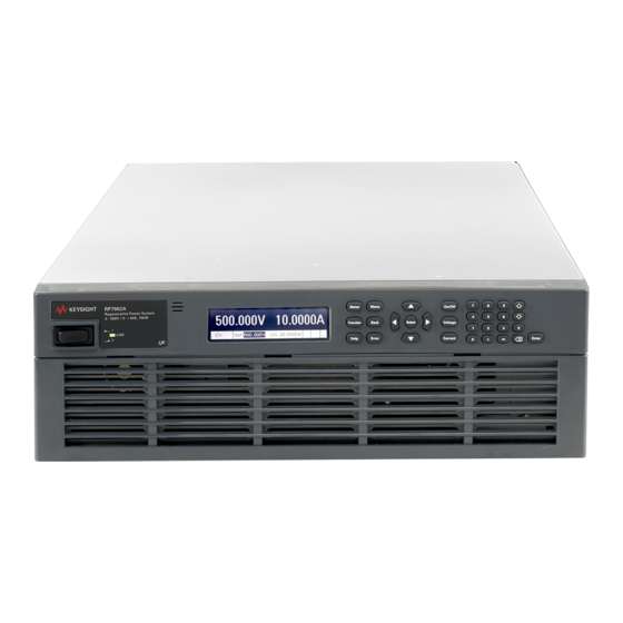
- Page 1 Keysight RP7900 Series Regenerative Power System This manual provides the documentation for the following instruments: RP7951AT, RP7952AT, N6991A, RP7951A, RP7952A, RP7953A, RP7961A, RP7962A, and RP7963A Advanced Service Guide...
- Page 2 Conformity. understood and met. where in the EULA. Keysight shall be under no obligation to update, revise or otherwise modify the Software. With WARNING respect to any technical data as defined by FAR 2.101, pursuant to FAR...
-
Page 3: Safety Notices
Failure to comply with these precautions or with specific warnings or instructions elsewhere in this manual violates safety standards of design, manufacture, and intended use of the instrument. Keysight Technologies assumes no liability of the customer’s failure to comply with the requirements. - Page 4 Improper actions can cause fatal injury as well as equipment damage. Note the instrument's external markings described under Safety Symbols and Regulatory Markings. Keysight RP7900 Series Advanced Service Guide...
- Page 5 Do not remove the instrument cover WARNING Only qualified, service-trained personnel who are aware of the hazards involved should remove instrument covers. Always disconnect the power cable and any external circuits before removing the instrument cover. Keysight RP7900 Series Advanced Service Guide...
- Page 6 Do not mod ify the instrument WARNING Do not install substitute parts or perform any unauthorized modification to the product. Return the product to a Keysight Sales and Service Office for service and repair to ensure that safety features are maintained. Fuses WARNING The instrument contains an internal fuse, which is not customer accessible.
-
Page 7: Safety Symbols And Regulatory Markings
Forty years is the expected useful life environment outside of the home. of the product. Keysight RP7900 Series Advanced Service Guide... -
Page 8: South Korean Class A Emc Declaration
이 기 기 는 업 무 용 환 경 에 서 사 용 할 목 적 으 로 적 합 성 평 가 를 받 은 기 기 로 서 가 정 용 환 경 에 서 사 용 하 는 경 우 전 파 간 섭 의 우 려 가 있 습 니 다 . 사용자 안내문은 " 업무용 방송통신기자재 " 에만 적용한다 . Keysight RP7900 Series Advanced Service Guide... -
Page 9: Waste Electrical And Electronic Equipment (Weee) Directive
To return this unwanted instrument, contact your nearest Keysight Service Center, or visit http://about.keysight.com/en/companyinfo/environment/takeback.shtml for more information. Sales and Technical Support To contact Keysight for sales and technical support, refer to the support links on the following Keysight websites: – www.keysight.com/find/RP7900 (product-specific information and support, software and documentation updates) –... - Page 10 THIS PAGE HAS BEEN INTENTIONALLY LEFT BLANK. Keysight RP7900 Series Advanced Service Guide...
-
Page 11: Table Of Contents
Before, During, and After Troubleshooting ..... .15 Introduction to the Titan HV (RP7900 Series) Architecture ..16 Titan HV architecture: . - Page 12 RP7900 Replaceable Parts List ....... 76 Keysight RP7900 Series Advanced Service Guide...
-
Page 13: Troubleshooting
Introduction to the Titan HV (RP7900 Series) Architecture General Troubleshooting Information List of Error Codes Hardware Troubleshooting Guide This chapter lists the possible errors and their description and discusses the procedures for troubleshooting the Keysight RP7900 Series Regenerative Power System. -
Page 14: Safety Precaution
Ensure that all safety precautions are observed during all phases of operation of this instrument. Failure to comply with these precautions or with specific warnings or instructions elsewhere in this manual or in the RP7900 Series Operating and Service Guide violates safety standards of design, manufacture, and intended use of the instrument. -
Page 15: Before, During, And After Troubleshooting
– DO NOT touch any location of the UUT as the HIGH RAIL VOLTAGE is slowly discharging (the RAIL LED is RED). – Wait 5 minutes or until the RAIL LED is OFF before performing any disassembly procedure. Keysight RP7900 Series Advanced Service Guide... -
Page 16: Introduction To The Titan Hv (Rp7900 Series) Architecture
– Control board and digital personality module (DPM) – Output board – Bias board – Customer interface board (P600 and carrier) [1] Limited distirbution/customers only. Not available for sale to the public on www.keysight.com. Keysight RP7900 Series Advanced Service Guide... -
Page 17: Titan Hv Architecture
Shown below is the block diagram for a Titan HV unit. – Titan HV 5 kW models (RP7951A/RP7961A): One pair of isolation board and regulation board. – Titan HV 10 kW models (RP7952A/RP7962A/RP7953A/RP7963A): Two pairs of isolation board and regulation board. Keysight RP7900 Series Advanced Service Guide... - Page 18 Model AC 3-phase input DC output RP7951A, RP7952A, RP7953A 208 Vrms 425 Vdc RP7961A, RP7962A, RP7963A 400 Vrms 980 Vdc Keysight RP7900 Series Advanced Service Guide...
- Page 19 During normal operation, if the supply voltage is above the UVLO threshold, the output of the photo-detector will drive the IGBTs of the output stage. Keysight RP7900 Series Advanced Service Guide...
- Page 20 Inhibit_R,Y,B depends on the Inverter_ON_R,Y,B to decide whether it needs to turn the gate drive on or off. If the Inhibit_R,Y,B signal goes low, the microprocessor will shut down the gate immediately. Keysight RP7900 Series Advanced Service Guide...
- Page 21 – The isolation board protects itself from ‘live’ conditions, such as local over temperature (OT) and rail over voltage (OV) or low voltage (LV). The source of a rail OV/LV will either be an issue with its input, an internal malfunction, or a regulation board malfunction. Keysight RP7900 Series Advanced Service Guide...
- Page 22 – It communicates using the PG signal from the front-end. Provides ±23 V to the isolation board Provides ±23 V to the regulation board Provides +12 V to the chassis fan Provides ±15 V to the control board Keysight RP7900 Series Advanced Service Guide...
- Page 23 — it depends on the unit model whether it is a high voltage or high current model. The output board will provide the second level of filtering to the output. Keysight RP7900 Series Advanced Service Guide...
- Page 24 Troubleshooting MASTER/SLAVE board operation – The master slave circuitry allows communication between the units. This allows the user to talk with only the master when paralleling units. Keysight RP7900 Series Advanced Service Guide...
- Page 25 – The P600 is the processor board, which will store the firmware. – The constellation board is the interface board, which is equipped with other communication peripherals such as the USB port, LAN port, and GPIB ports. Keysight RP7900 Series Advanced Service Guide...
-
Page 26: General Troubleshooting Information
Troubleshooting General Troubleshooting Information Refer to the RP7900 Series Operating and Service Guide for more details on the recommended ETE information. Keysight SD1000A SDS (safety Model Firmware d isconnect system) port functionality RP7951AT, RP7952AT, N6991AT B_01_02_730 Available RP7951, RP7952A, RP7953A, RP7961A,... -
Page 27: List Of Error Codes
31. Measurement cal constants out of range The measurement calibration constant is outside the acceptable range. Over vol tage cal constants out of range The over voltage calibration constant is outside the acceptable range. Keysight RP7900 Series Advanced Service Guide... - Page 28 The calibration file was written or read using old firmware. The firmware must be updated. Running backup firmware Check the P600 firmware programming The instrument is presently running the backup (previous) version of the firmware. Keysight RP7900 Series Advanced Service Guide...
- Page 29 Cannot initiate transient generator. Either the voltage or current function is set to Fixed mode. The command is not supported by this model This instrument either does not have the hardware capability or the options required to support this command. Keysight RP7900 Series Advanced Service Guide...
- Page 30 Master/slave error Check the master/slave connection or the hardware An error has occurred in the master/slave configuration Safety Disconnect error Check the SDS connection or the hardware An error has occurred in the SDS unit. Keysight RP7900 Series Advanced Service Guide...
-
Page 31: Hardware Troubleshooting Guide
– DC electronic load: EA-EL 9750-75HP or Chroma 63206A-1200-240A or equivalent – Digital multimeter – Keysight high performance Infiniium oscilloscope – Current probe – Differential probe – Guild-line shunt – DC power supply – Cables and connectors Keysight RP7900 Series Advanced Service Guide... -
Page 32: Hardware Trouble Shooting Procedure
Troubleshooting Hardware trouble shooting procedure 1 Visually inspect all the LED indicators as shown below: Figure 1-1 Location of the LED indicators Keysight RP7900 Series Advanced Service Guide... - Page 33 – Red LED flashing and green LED off indicates that a fault code is being annunciated. C DPM processor LED – Green LED indicates that the unit has booted up properly. D AC mod ule rail LED – Red LED indicates that there is rail voltage present. Keysight RP7900 Series Advanced Service Guide...
- Page 34 – Disconnect the cable connecting the isolation board to the regulation board to verify that the isolation is good. – Disconnect the cable from the regulation board to the output board to verify that the regulation is good. Keysight RP7900 Series Advanced Service Guide...
- Page 35 16.013 W [a] Instrument setting - Voltage: 20 V, Current: 1 A [b] Instrument setting - Voltage: 500 V, Current: 8 A 8 Refer to the troubleshooting flow chart in Figure 1-3 for further details. Keysight RP7900 Series Advanced Service Guide...
- Page 36 Check the backplane connectors. control board Vmon and • Check the FFC cable connecting to the control board. Imon signals are good. • Swap the control board. Swap the DPM Figure 1-3 Hardware troubleshooting flow chart Keysight RP7900 Series Advanced Service Guide...
- Page 37 RP7951A, RP7952A, RP7953A, RP 7951AT, RP7952AT, N6991A (3-phase, 208 V models) Isolation Brd Output 565Vdc PFC AC Output 425Vdc 425V and 10V PG goes into the Bias Brd Figure 1-4 Bias voltage test points for 3-phase, 208 V models Keysight RP7900 Series Advanced Service Guide...
- Page 38 RP7961A, RP7962A, RP7963A (3-phase, 480 V models) Isolation Brd Output 565Vdc PFC AC Output 980Vdc 980V and 10V PG goes into the Bias Brd Figure 1-5 Bias voltage test points for 3-phase, 480 V models Keysight RP7900 Series Advanced Service Guide...
-
Page 39: Disassembly
Disassembly Tips Disassembly Procedures This chapter discusses the disassembly procedures for troubleshooting and repairing the Keysight RP7900 Series Regenerative Power System. SHOCK HAZARD. Only qualified, service-trained personnel who are aware of WARNING the hazards involved should remove instrument covers. Always disconnect the power cable and any external circuits before removing the instrument cover. -
Page 40: Electrostatic Discharge (Esd) Precautions
– Use a conductive wrist strap to reduce static accumulation. – Minimize handling. – Keep replacement parts in original static-free packaging. – Remove all plastic, foam, vinyl, paper, and other static-generating materials from the immediate work area. Keysight RP7900 Series Advanced Service Guide... -
Page 41: Disassembly Tools
Removing the fan bracket assembly from the chassis 7 mm Hex driver Removing the output and back plane assembly 8 mm Hex driver Removing the PFC control board 9/32 Hex driver Removing the GPIB board from the chassis Keysight RP7900 Series Advanced Service Guide... -
Page 42: Disassembly Tips
After installation, check the cable to ensure the cable is straight and securely aligned within the connector. Assembly procedures To assemble the instrument, reverse the procedures described in the “Disassembly Procedures” on page 43. Keysight RP7900 Series Advanced Service Guide... -
Page 43: Disassembly Procedures
1 First, remove all cables, wires, or power cord that are connected to the instrument before performing any disassembly. 2 Remove the 7 screws (0515-1946) on the top chassis of the instrument. 3 Next, remove the 3 screws (0515-0430) at the rear panel of the instrument. Keysight RP7900 Series Advanced Service Guide... - Page 44 5 Gently remove the top chassis cover (5003-2346). Ensure that a proper insulator is installed on the top cover. If the existing NOTE insulator is damaged or worn out, please replace the existing insulator with a new insulator (5188-9218). Keysight RP7900 Series Advanced Service Guide...
-
Page 45: Removing The Pfc Control Board
Disassembly Removing the PFC control board 1 First, remove all the cables that are connected to the PFC control board. 2 Next, remove the 2 screws (0515-0430) shown below. Keysight RP7900 Series Advanced Service Guide... - Page 46 Disassembly 3 Then, unsecure the 2 screws (0515-0430) shown below from the chassis. 4 Use an 8 mm Hex driver to remove the nut-hex (0535-0077) and then remove the flat washer lock (2190-0629). Keysight RP7900 Series Advanced Service Guide...
- Page 47 Disassembly 5 Flip the instrument to its bottom to remove the 5 screws (0515-1946) shown below. 6 Finally, pull out the PFC control board from the chassis. Keysight RP7900 Series Advanced Service Guide...
-
Page 48: Removing The Digital Personality Module Pca
Removing the digital personality module PCA 1 First, gently unlock the connector pin and pull out the digital personality module PCA (5067-5271) from its casing. 2 Next, remove the screw on the digital personality module PCA bracket. Keysight RP7900 Series Advanced Service Guide... - Page 49 Disassembly 3 Then, remove the screw securing the control PCA to the constellation bracket. 4 Next, remove the bias control cable. Keysight RP7900 Series Advanced Service Guide...
- Page 50 Disassembly 5 Then, remove the constellation FFC cable at the back of the digital personality module PCA. 6 Finally, remove the control insulator from the constellation bracket. Keysight RP7900 Series Advanced Service Guide...
-
Page 51: Removing The Isolation And Isolation Attic Board (Top And Bottom) From The Chassis
1 First, remove the air guard insulator and cables from the isolation and isolation attic board. 2 Next, remove the 10 screws (0515-0430) shown below on the isolation PCA and isolation attic PCA. Keysight RP7900 Series Advanced Service Guide... - Page 52 3 Then, remove both PCAs from the chassis module by removing the 12 screws (0515-0667) shown below. 4 Finally, remove the 400 V isolation attic PCA (5067-6590) from the 400 V AC in isolation PCA (5067-6589) as shown below. Keysight RP7900 Series Advanced Service Guide...
- Page 53 Disassembly Set aside the 400 V isolation attic PCA and the 400 V AC in isolation PCA. Keysight RP7900 Series Advanced Service Guide...
-
Page 54: Removing The Regulation Magnitcs Pca From The Regulation Pca
1 First, remove the 8 screws (0515-0430) shown below securing the regulation magnitcs PCA to the regulation PCA. 2 Next, remove both PCAs from the chassis by removing the 12 screws (0515-0667) shown below. Keysight RP7900 Series Advanced Service Guide... -
Page 55: Removing The Isolation Partition, Insulator Regulation, And Chassis Module
3 Finally, remove the regulation magnitcs PCA from the regulation PCA as shown below. Removing the isolation partition, insulator regulation, and chassis module 1 First, remove the isolation partition (5066-1924) from the chassis module. Keysight RP7900 Series Advanced Service Guide... - Page 56 Disassembly 2 Next, remove the insulator regulation (5188-9219) from the chassis module. 3 Then, remove the 6 screws (0515-0430) shown below securing the chassis module to the rear tray. Keysight RP7900 Series Advanced Service Guide...
- Page 57 Disassembly 4 Flip over the chassis. Remove the 8 screws (0515-1946) shown below securing the chassis module to the chassis. 5 Finally, remove the chassis module from the chassis. Keysight RP7900 Series Advanced Service Guide...
-
Page 58: Removing The Output And Back Plane Assembly
Disassembly Removing the output and back plane assembly 1 First, remove the 2 screws (0515-0430) shown below. 2 Next, tear off the “+ (red)” and “– (black)” labels on the output terminal. Keysight RP7900 Series Advanced Service Guide... - Page 59 3 Then, remove the 2 screws (0515-0382) shown below to securing the bezel to the buss bar using a T-20 Torx driver and a 7 mm Hex driver. The screws are secured using a nut-hex (0535-1097) and a flat washer lock (3050-0893) as shown below. Keysight RP7900 Series Advanced Service Guide...
- Page 60 Disassembly 4 Remove the 2 screws (0515-0372) shown below securing the bezel plate (5066-1911). 5 Finally, pull out the output and backplane assembly from the chassis as shown below. Keysight RP7900 Series Advanced Service Guide...
-
Page 61: Removing The Bias Bracket From The Chassis
Removing the bias bracket from the chassis 1 First, remove all the cables attached on this board. 2 Next, remove the bias bracket from the chassis by removing the 3 screws (0515-1946) shown below. Keysight RP7900 Series Advanced Service Guide... -
Page 62: Removing The Constellation And P600 Assembly From The Chassis
Removing the constellation and P600 assembly from the chassis 1 First, remove the 3 screws (0515-1946) shown below securing the constellation and P600 assembly to the chassis. 2 Next, remove the constellation and P600 assembly from the chassis. Keysight RP7900 Series Advanced Service Guide... - Page 63 (on both sides of the cable) using a glue gun to secure the FFC cable to the constellation and P600 assembly. Ensure that the FFC cable is inserted properly before applying the glue. Keysight RP7900 Series Advanced Service Guide...
-
Page 64: Removing The Gpib Board From The Chassis
Removing the GPIB board from the chassis 1 First, remove the 2 standoff-hex screws (0380-5630) shown below securing the GPIB board to the chassis using a 9/32 Hex driver. 2 Next, pull the GPIB board out from the chassis. Keysight RP7900 Series Advanced Service Guide... -
Page 65: Removing The Io Board From The Chassis
Removing the IO board from the chassis 1 First, remove the IO board from the chassis by removing the 2 screws (0515-0430) shown below. 2 Next, pull the IO board out from the chassis. Keysight RP7900 Series Advanced Service Guide... -
Page 66: Removing The Front Panel From The Chassis
Disassembly Removing the front panel from the chassis 1 First, remove the FFC cable connected to the front panel display. Keysight RP7900 Series Advanced Service Guide... - Page 67 – When reconnecting the FFC cable to the front panel display, reapply the glue (on both sides of the cable) using a glue gun to secure the FFC cable to the front panel display connector. Keysight RP7900 Series Advanced Service Guide...
- Page 68 Disassembly 2 Next, remove the AC switch cable (5188-9483) on the front panel. 3 Then, remove the screws on the right and left side of the front panel. Keysight RP7900 Series Advanced Service Guide...
-
Page 69: Removing The Front Frame Vent From The Chassis
4 Finally, pull out the front panel from the chassis as shown below. Removing the front frame vent from the chassis 1 First, remove the 2 screws (0515-1103) on the right side and left side of the front frame vent. Keysight RP7900 Series Advanced Service Guide... -
Page 70: Removing The Fan Bracket Assembly From The Chassis
2 Next, pull out the front frame vent (5066-1923) as shown below. Removing the fan bracket assembly from the chassis 1 First, flip the chassis over and remove the 3 screws (0515-1946) shown below securing the fan bracket assembly to the chassis. Keysight RP7900 Series Advanced Service Guide... - Page 71 Disassembly 2 Remove the 2 screws (0515-1946) on the right side and left side of the fan bracket assembly as shown below. 3 Remove the fan bracket assembly as shown below. Keysight RP7900 Series Advanced Service Guide...
- Page 72 4 Finally, remove the 4 bumper feet (0403-1294) shown below using a flat blade driver. You will need to use a mallet and a slot screwdriver to assemble back the 4 NOTE bumper feet to the chassis. Keysight RP7900 Series Advanced Service Guide...
- Page 73 Disassembly Keysight RP7900 Series Advanced Service Guide...
- Page 74 Disassembly Keysight RP7900 Series Advanced Service Guide...
-
Page 75: Replaceable Parts
Keysight RP7900 Series Regenerative Power System Advanced Service Guide Replaceable Parts RP7900 Replaceable Parts List The following table documents the replaceable parts description, Keysight part numbers, and applicable models. -
Page 76: Rp7900 Replaceable Parts List
TESTED PCA HV TITAN 480VAC ATTIC BOARD ✔ ✔ ✔ 5067-6718 TESTED PCA HV TITAN ISOLATION ✔ ✔ ✔ ✔ ✔ ✔ 5067-6727 TESTED PCA HV TITAN HV RAIL ISOLATION BOARD - 480VAC ✔ ✔ ✔ Keysight RP7900 Series Advanced Service Guide... - Page 77 CONSTELLATION FLEXIBLE FLAT CABLE ✔ ✔ ✔ ✔ ✔ ✔ ✔ ✔ ✔ 5003-2346 COVER TOP ✔ ✔ ✔ ✔ ✔ ✔ ✔ ✔ ✔ 0403-1294 FOOT STAND ✔ ✔ ✔ ✔ ✔ ✔ ✔ ✔ ✔ Keysight RP7900 Series Advanced Service Guide...
- Page 78 MENTOR CONNECTOR-HEADER VERTICAL SMT 70-PIN 2MM 3.2A 1254-2880 ✔ ✔ ✔ ✔ ✔ ✔ ✔ ✔ ✔ 2-ROW NUT-HEX W/LOCK-WASHER M3X0.5 2.4MM-THK 5.5MM-A/F 0535-0031 ✔ ✔ ✔ ✔ ✔ ✔ ✔ ✔ ✔ STEEL NI-PLATED Keysight RP7900 Series Advanced Service Guide...
- Page 79 SCREW-MACHINE W/CREST-CUP-CON-WASHER PAN-HD 0515-0430 ✔ ✔ ✔ ✔ ✔ ✔ ✔ ✔ ✔ TORX-T10 M3X0.5 6MM-LG SST-300 PASSIVATED SCREW-MACHINE W/CREST-CUP-CON-WASHER PAN-HD 0515-0430 ✔ ✔ ✔ ✔ ✔ ✔ ✔ ✔ ✔ TORX-T10 M3X0.5 6MM-LG SST-300 PASSIVATED Keysight RP7900 Series Advanced Service Guide...
- Page 80 WASHER-FLAT METALLIC 4.2MM-ID 8MM-OD 0.8MM-THK STEEL 3050-2376 ✔ ✔ ✔ ✔ ✔ ✔ ✔ ✔ ✔ NI-PLATED WASHER-FLAT METALLIC 4.4MM-ID 8.85MM-OD 0.8MM-THK SST 3050-0893 ✔ ✔ ✔ ✔ ✔ ✔ ✔ ✔ ✔ PASSIVATED Keysight RP7900 Series Advanced Service Guide...
- Page 81 WASHER-LOCK HELICAL 4.1MM-ID 7.6MM-OD 0.9MM-THK SST 2190-0586 ✔ ✔ ✔ ✔ ✔ ✔ ✔ ✔ ✔ PASSIVATED WINDOWS EMBEDDED COMPACT OTHER MOBILE 7 EMB ESD OEI 9010-0321 ✔ ✔ ✔ ✔ ✔ ✔ ✔ ✔ ✔ (C7P) RUNTIME/LICENSE Keysight RP7900 Series Advanced Service Guide...
- Page 82 Replaceable Parts THIS PAGE HAS BEEN INTENTIONALLY LEFT BLANK. Keysight RP7900 Series Advanced Service Guide...
- Page 83 This information is subject to change without notice. Always refer to the Keysight website for the latest revision. © Keysight Technologies 2019 Edition 1, July 11, 2019 Printed in Malaysia *RP7900-90000* RP7900-90000 www.keysight.com...
Need help?
Do you have a question about the RP7900 Series and is the answer not in the manual?
Questions and answers