
Related Manuals for Keysight N6751A


Summary of Contents for Keysight N6751A
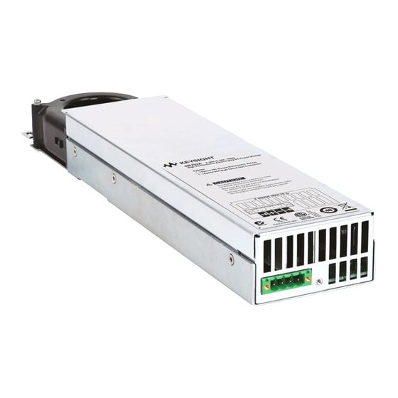
- Page 1 DUT Power Supply for Keysight i3070 Series 6 In-Circuit Test System DUT power supply models: N6751A N6773B N6752A N6746A Installation Guide...
- Page 2 DFARS and are set forth THIS DOCUMENT THAT CONFLICT specifically in writing elsewhere in the WITH THESE TERMS, THE WARRANTY EULA. Keysight shall be under no TERMS IN THE SEPARATE AGREEMENT obligation to update, revise or WILL CONTROL.
-
Page 3: Table Of Contents
Contents N67xx DUT Power Supply Overview ..........1-2 Installing the DUT Power Supply . -
Page 5: N67Xx Dut Power Supply
This guide describes the installation of the N67xx DUT power supplies in the i3070 Series 6 test systems (2- or 4-module). The procedures in this document must be performed by personnel who are trained and qualified to service Keysight systems. -
Page 6: Overview
Overview The DUT power supplies are installed in the rack(s) behind the i3070 Series 6 testhead. Figure 1-1 shows the location of DUT power supplies in a 4-module system (rear view, service position). A 2-module system contains only Bank 2 and one rack for the DUT power supplies. - Page 7 Part Numbers Table 1-1 For DUT power supply installation Part Number Description Quantity Brackets N1808-01212 Bracket, DUTPS - Rear N1808-01217 Bracket, DUTPS - Front E9900-06001 Screw (A pair of front brackets and a pair of rear brackets required for each DUT power supply.) Cables N1807-61622 Module Cable 4 Channel;...
-
Page 8: Installing The Dut Power Supply
Universal AC input - DUT power supplies have universal input voltage capability with active power factor correction. Inventory the DUT power supply kit. Compare the part numbers and quantities of parts to the Parts List in the kit. Report any discrepancies to your Keysight support representative. Preparation: a Remove any test fixture that may be on the system. - Page 9 Connect the output cables to the ASRU Cards and DUT power supplies. Connecting the Output Cables on page 1-6. To set up Fault/Inhibit system protection, see Setting Up Fault/Inhibit System Protection on page 1-19. Connect the power and GPIB cables as described in Connecting the Power and GPIB Cables on page 1-25.
-
Page 10: Connecting The Output Cables
Connecting the Output Cables When adding a supply, the configuration of existing supplies may prevent you from following all of these procedures. Do not reconfigure existing supplies. Reconfiguring existing supplies is likely to cause previously developed board tests to fail. These instructions are for a system being configured for the first time. -
Page 11: Connecting Output Cables For N6751
Connecting Output Cables for N6751 The DUT power supply connections are J4 and J9 on the ASRU Card. The ASRU Card end of the cable can be either a 34-pin connector or a 20-pin connector. The 34-pin connector is for ASRU channels 1–4, and the 20-pin connector is for channels 5–6. - Page 12 Table 1-3 Connector B to J9 on ASRU Card Wire Color Wire Size Con/Terminal WHT/BRN WHT/BRN WHT/BLK WHT/BLK WHT/ORN WHT/ORN WHT/RED WHT/RED N67xx DUT Power Supply Installation...
- Page 13 Connecting to the ASRU Card Connecting to Channels 1 through 4 The N6751 is a 4-output DUT power supply. One ASRU channel is required for each output. Locate the highest numbered module with channels 1 through 4 available on the ASRU Card. If channels 1 through 4 are not available, see Connecting to Channels 5 and 6 on page 1-10.
- Page 14 Connecting to Channels 5 and 6 If channels 1 through 4 are not available in any module, cable the N6751 supply to a bank where both modules have channels 5 and 6 available. Split the outputs as shown in Figure 1-6.
-
Page 15: Connecting Output Cables For N6752
Connecting Output Cables for N6752 Connecting to the ASRU Card Connecting to the Utility Card Connecting to the ASRU Card The N6752 is a 2-output, high-current DUT power supply. Two ASRU channels are required for each output to handle the high current. Both power outputs can be routed to any single module or they can be split across two modules in the same bank. - Page 16 Figure 1-7 N6752 output connections – Channels 5 & 6 Channels 5 & 6 L1 L2 L3 L4 K1 K2 K3 K4 Label on cable Cable color BLK/WHT – BRN/WHT –S RED/WHT – ORN/WHT –S 1-12 N67xx DUT Power Supply Installation...
- Page 17 Figure 1-8 N6752 output connections – Channels 1 through 4 Channels 2 & 3 Channels 1 & 4 G1 G2 G3 G4 F1 F2 F3 F4 H1 H2 H3 H4 J1 J2 J3 J4 Label on cable Cable color Label on cable Cable color BLU/WHT BLK/WHT...
- Page 18 Connecting to the Utility Card The Utility Card provides an additional two channels of high current output (channels 7–8). The power supply connector on the card is J601. Table 1-4 Connector A to J601 on Utility Card Wire Color Wire Size Con/Terminal CH7 S+ CH7 S–...
- Page 19 Figure 1-9 N6752 output connections – Channels 7 and 8 (Utility Card) Channel 8 Channel 7 + – + – + – + – – – Label on cable Cable color Label on cable Cable color CH8 S+ CH7 S+ CH8 + BLK/BRN CH7 +...
-
Page 20: Connecting Output Cables For N6773
Connecting Output Cables for N6773 Connecting to the ASRU Card Connecting to the Utility Card Connecting to the ASRU Card The N6773 DUT Power Supply is a one-output, high-current supply. It can only be connected to channels 5 and 6 on the ASRU Card. Two ASRU channels are required to handle the high current. - Page 21 Connecting to the Utility Card The N6773 DUT Power Supply can be connected to channel 7 or 8 on the Utility Card as shown Figure 1-11. Figure 1-11 N6773 output connections – Channels 7 or 8 (Utility Card) Channel 7 or 8 + –...
-
Page 22: Connecting Output Cables For N6746
Connecting Output Cables for N6746 Power from the N6746 power supply can be routed to any single module, but must use either ASRU channel 5 or 6. It is recommended that you use ASRU channel 6 as a first choice when configuring this supply. Up to four power outputs can be routed to any single module or they can be split across four modules. -
Page 23: Setting Up Fault/Inhibit System Protection
Setting Up Fault/Inhibit System Protection To set up Fault/Inhibit system protection, an OVL sense cable is required. Refer to the following sections: • Digital Control Port • What is Being Connected in ICT? Table 1-5 OVL sense cable Part number Description 03066-61623 OVL sense cable, 67xx DUT power supply... -
Page 24: Digital Control Port
Digital Control Port An 8-pin connector and a quick-disconnect connector plug are provided for accessing the digital control port functions. The digital control connector accepts wires sizes from AWG 14 to AWG 30. Note that wire sizes smaller than AWG 24 are not recommended. Disconnect the connector plug to make your wire connections. -
Page 25: What Is Being Connected In Ict
What is Being Connected in ICT? • Fault Output • Inhibit Input • Fault/Inhibit System Protection • Clearing a System Protection Fault Fault Output Pins 1 and 2 can be configured as a fault-output pair. The polarity of pin 1 can also be configured. - Page 26 Inhibit Input Pin 3 can be configured as a remote inhibit input. The polarity of pin 3 can also be configured. Pin 8 is the common for pin 3. The Inhibit Input function lets an external input signal control the output state of all the output channels in the DUT power supply.
- Page 27 Fault/Inhibit System Protection The following figure illustrates some ways that you can connect the Fault/Inhibit pins of the connector. As shown above, when the Fault outputs and Inhibit inputs of several DUT power supplies are daisy-chained, an internal fault condition in one of the DUT power supplies will disable all of them without intervention by either the controller or external circuitry.
- Page 28 From the front panel: Select Protect/Clear. Select the Clear button. Using SCPI command: To clear a protection fault on output1, execute OUTP:PROT:CLE(@1) 1-24 N67xx DUT Power Supply Installation...
-
Page 29: Connecting The Power And Gpib Cables
Connecting the Power and GPIB Cables Plug the DUT Power Supply’s power cord into the nearest power outlet box, with the proper voltage, in the testhead. Each outlet box is marked with its voltage. Connect 0.5-meter GPIB cables (10833D) to existing supplies. The DUT power supplies handshake faster than most other devices on the bus. - Page 30 Programming the GPIB Address on Power Supplies Table 1-8 shows the valid GPIB addresses for DUT power supplies. Be sure not to duplicate a GPIB address if making changes. Set the GPIB address from the front panel of the DUT power supply. Press ADDR and enter the address.
- Page 31 Table 1-8 DUT Power Supply Addressing (continued) Power Supply Connection GPIB Address Device File (in /dev/) Module 0, Utility Card channel 7 or 7-8 ps12 Module 0, Utility Card channel 8 ps13 Module 1, Utility Card channel 7 or 7-8 ps14 Module 1, Utility Card channel 8 ps15...
-
Page 32: Updating The Configuration Files
Updating the Configuration Files The power supply connections must be defined in the system and standard config files: \I3070_ICT_ROOT\diagnostics\th1\config \I3070_ICT_ROOT\standard\config Use the statement. supplies supplies <type> <#> asru channel <#> • The supplies type can be ps6751, ps6752, ps6746, or ps6773 depending on which power supply was installed. - Page 33 Table 1-9 Default and alternative power supply mapping Module 2 Module 0 !supplies ps6751 5 to 8 asru channels 1 to 4 supplies ps6751 13 to 16 asru channels 1 to 4 supplies ps6752 5 to 6 asru channels 1 to 4 !supplies ps6752 13 to 14 asru channels 1 to 4 !supplies ps6751 19 to 20 asru channels 5 to 6 !supplies ps6751 23 to 24 asru channels 5 to 6...
-
Page 34: Verifying Operation
Some supplies come from the factory with shorting straps. They must be removed to do remote sensing. In Case of Difficulty If you need phone support, go to www.keysight.com/find/contactus for contact information. 1-30 N67xx DUT Power Supply Installation... -
Page 35: Replacement Procedures
Keysight i3070 In-Circuit Test System N67xx DUT Power Supply Installation Replacement Procedures Replacing a Power Module Replacing Connectors on Old Output Cables... -
Page 36: Replacing A Power Module
Replacing a Power Module Turn the DUT power supply off and disconnect the power cable before removing and installing power modules. Observe all standard electrostatic discharge precautions before handling electronic components. Always replace a power module with the same model, otherwise the DUT power supply cannot be controlled by the i3070 In-Circuit Test Software. - Page 37 Align the new power module over the pins and push it down onto the connector. Secure with the screws at each end of the power module. Because the RFI strips apply upward pressure, continue pushing down on the module until the screws are tight.
-
Page 38: Replacing Connectors On Old Output Cables
Replacing Connectors on Old Output Cables The output cables from some older i3070 systems can be used with the N67xx DUT power supplies by cutting off the lugs and rewiring them based on the diagrams in Connecting the Output Cables. Note that the labels on new output cables are different from the old cables, and the wiring information in this chapter refer to the new labels. - Page 39 Table 2-3 Mapping old and new labels on output cables (E4000-61606, 2-module) Label on Cable: Label on Cable: Cable Color Cable Color BLK/RED RED/BLK – BRN/RED – ORN/WHT –S –S Table 2-4 Mapping old and new labels on output cables (E4000-61602, 4-module) Label on Cable: Label on Cable:...
- Page 40 This information is subject to change without notice. © Keysight Technologies 2019 Edition 1, July 2019 E4000-90024 www.keysight.com...
Need help?
Do you have a question about the N6751A and is the answer not in the manual?
Questions and answers