
Related Manuals for Keysight MP4303A


Summary of Contents for Keysight MP4303A
- Page 1 MP4300 Series Modular Power System MP4301A, MP4302A, MP4303A, MP4304A Mainframes MP4361A, MP4362A, MP4351A, MP4352A SAS Power Modules OPERATING AND SERVICE GUIDE...
-
Page 3: Table Of Contents
AC Mains Connections AC Mains Considerations Power Cable Connections Output Connections Wiring Considerations Single Load Connections Multiple Load Connections Remote Sense Connections Paralleled Channel Connections Parallel Connections Interface Connections LAN Connections - site and private Keysight MP4300 Series Operating and Service Guide... - Page 4 Current Sinking Operation Current Sinking Regenerative Operation Programming Output Protection Introduction Set the Overvoltage Protection Set the Overcurrent Protection Clear Output Protection Using Power Limit Protection Making Measurements Average Measurements Programming the Digital Port Keysight MP4300 Series Operating and Service Guide...
- Page 5 MEMory Subsystem OUTPut Subsystem POWer Command [SOURce] Subsystem STATus Subsystem SYSTem Subsystem VOLTage Subsystem Status Tutorial Status Registers EDP Status Register UNR Status Register Standard Event Status Group Questionable Status Groups Operation Status Group Keysight MP4300 Series Operating and Service Guide...
- Page 6 Software Required Update Procedure Calibration Switches Accessing the Calibration Switch Switch Functions Battery Replacement Replacing the Battery Cleaning Cleaning the Outside Cleaning the Filter Disassembly Electrostatic Discharge (ESD) Precautions Tools Required Remove Maintenance Cover Keysight MP4300 Series Operating and Service Guide...
- Page 7 Access the Calibration Switches and the Battery Index Keysight MP4300 Series Operating and Service Guide...
-
Page 8: Legal And Safety Information
No part of this manual may be reproduced in any form or by any means (including electronic storage and retrieval or translation into a foreign language) without prior agreement and written consent from Keysight Technologies as governed by United States and international copyright laws. Keysight Technologies... -
Page 9: Warranty
EULA shall apply, except to the extent that those terms, rights, or licenses are explicitly required from all providers of commercial computer software pursuant to the FAR and the DFARS and are set forth specifically in writing elsewhere in the EULA. Keysight shall be under no obligation to update, revise or otherwise modify the Software. -
Page 10: Safety And Regulatory Symbols
The RCM mark is a registered trademark of the Australian Communications and Media Authority. Indicates United Kingdom Conformity Assessed. Contains one or more of the 6 hazardous substances above the maximum concentration value (MCV), 40 Year EPUP. Keysight MP4300 Series Operating and Service Guide... -
Page 11: Safety Notices
Failure to comply with these precautions or with specific warnings or instructions elsewhere in this manual violates safety standards of design, manufacture, and intended use of the instrument. Keysight Technologies assumes no liability of the customer’s failure to comply with the requirements. - Page 12 Do Not Modify the Instrument Do not install substitute parts or perform any unauthorized modification to the product. Return the product to a Keysight Sales and Service Office for service and repair to ensure that safety features are maintained. Readings and State Reported by the Browser Web Control Page.
- Page 13 Do not attempt to clean internally. In Case of Damage Instruments that are not functioning correctly, appear damaged or defective should be made inoperative and secured against unintended operation until they can be repaired by qualified service personnel. Keysight MP4300 Series Operating and Service Guide...
-
Page 14: Symboles De Sécurité
établies lors de la conception, de la fabrication et de l’usage normal de l’instrument. Keysight Technologies ne saurait être tenu pour responsable du non-respect de ces consignes. - Page 15 Seules des personnes qualifiées, formées à la maintenance et conscientes des risques d’électrocution encourus peuvent démonter les capots de l’instrument. Débranchez toujours le cordon d’alimentation et tous les circuits externes avant de démonter le capot de l’instrument. Keysight MP4300 Series Operating and Service Guide...
- Page 16 N’installez pas de composants de remplacement et n’apportez aucune modification non autorisée à l’appareil. Pour garantir les caractéristiques de sécurité de l’instrument, retournez-le à votre bureau de vente et d’après-vente Keysight le plus proche en vue d’une opération de maintenance et de réparation.
-
Page 17: Quick Reference
You can download the latest version of this document at www.keysight.com/find/MPS-doc. If you have questions about your shipment, or if you need information about warranty, service, or technical support, contact Keysight Technologies. Contacting Keysight Technologies www.keysight.com/find/assist for information on contacting Keysight... -
Page 18: Introduction To The Instrument
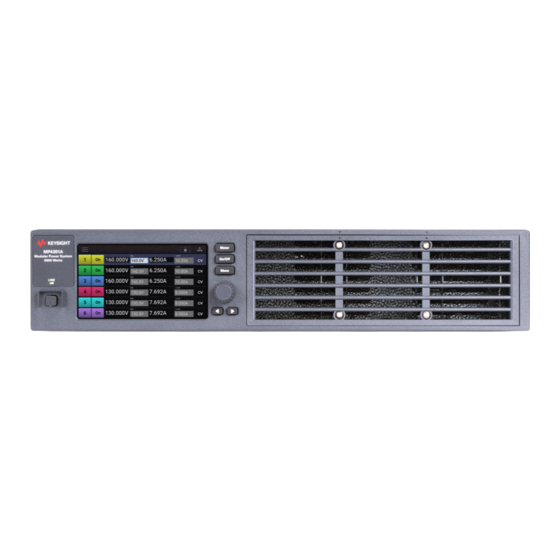
Front Panel Keys at a Glance Modular Power System at a Glance The Keysight Modular Power System (MPS) series include 2U rack-mountable mainframe with user- installable power modules with performance and features that are optimized for automated test systems. The output and system features are described as follows. The... -
Page 19: Front Panel At A Glance
4. Rotary knob- Scrolls through the display selections. Push to make a selection. 5. Navigation keys - Move horizontally across the selections on the display. 6. Air inlets - Do not block front panel air inlets. Keysight MP4300 Series Operating and Service Guide... -
Page 20: Rear Panel At A Glance
8. Module connectors - Includes sense and output connections for each power module. Up to six single slot modules can be installed in an MPS mainframe. 9. Lockout bar - Must be installed to operate power modules. Keysight MP4300 Series Operating and Service Guide... -
Page 21: Front Panel Display At A Glance
Using the Front Panel for more information. Channel 1 Details Grouped Channels In this view, power modules installed in slots 2 and 3 are grouped with channel 1. Channel 1 addresses all three grouped channels. Keysight MP4300 Series Operating and Service Guide... - Page 22 CSF = the output is disabled by current-sharing fault protection FLT = the output is disabled by a hardware fault; cycle power to clear FPL = the output is disabled by the mainframe power limit being exceeded. Keysight MP4300 Series Operating and Service Guide...
-
Page 23: Front Panel Keys At A Glance
Pushing the knob again will choose the option from the list. Arrow keys let you navigate around the display in the same manner as the Rotary knob. Keysight MP4300 Series Operating and Service Guide... -
Page 24: Front Panel Menu Reference
Configures the Digital IO port Help Back Back to previous level Error Queue Displays the error messages Reading the messages deletes them About Instrument Displays Mainframe serial number and firmware version Displays power module information Keysight MP4300 Series Operating and Service Guide... -
Page 25: Command Quick Reference
Returns the averaged measurement. :VOLTage [:DC]? (@<chanlist>) Returns the averaged measurement. HCOPy :SDUMp :DATA? [JPG|PNG] Returns an image of the front panel display. :DATA :FORMat JPG|PNG Specifies the format for front panel images returned. Keysight MP4300 Series Operating and Service Guide... - Page 26 Turns the front panel LXI identify indicator on or off. :MDNS [:STATe] 0|OFF|1|ON Sets the MDNS state MEASure [:SCALar] :CURRent [:DC]? (@<chanlist>) Takes a measurement; returns the averaged current. :VOLTage [:DC]? (@<chanlist>) Takes a measurement; returns the averaged voltage. Keysight MP4300 Series Operating and Service Guide...
- Page 27 Resets the latched protection. :COUPle 0|OFF|1|ON Enables or disables channel coupling for protection faults. :OT :AMBient:MARGin? Returns the difference between over-temp and ambient temp. :TUNNel:MARGin? (@<chanlist>) Returns the difference between heatsink over-temp and temp. Keysight MP4300 Series Operating and Service Guide...
- Page 28 :ISC <value>, (@<chanlist>) Sets the Isc current of the curve in SAS mode. :SCALe <percent>, (@<chanlist>) Specifies the current scale in SAS mode. :TABLe :NAME <name, (@<chanlist> Activates a table when operating in Table mode. Keysight MP4300 Series Operating and Service Guide...
- Page 29 Specifies the voltage scale in SAS mode. :VMP <value> Sets the voltage at the Vmp point of the curve in SAS mode. :VOC <value> Sets the Voc voltage of the curve in SAS mode. Keysight MP4300 Series Operating and Service Guide...
- Page 30 :DELete (@<channel>) Removes the specified channel from the group. :ALL Deletes all groups. :TIME <hh>, <mm>, <ss> Sets the time of the system clock. :VERSion? Returns the SCPI version that the instrument complies with. Keysight MP4300 Series Operating and Service Guide...
-
Page 31: Model Features And Options
Filler module kit (contains 5 filler modules for installing in unused slots) Keysight 1CP104A Rack mount kit with handles - for use with MP4301A and MP4302A Keysight RP7908A Rack rails for Keysight racks or similar designs Keysight MP4300 Series Operating and Service Guide... -
Page 32: Specifications And Characteristics
5 From 20 Hz to 20 MHz with 5 ohms in parallel with ≥400 nF, terminals ungrounded, or either terminal grounded 6 From 20 Hz to 10 MHz with 5 ohms in parallel with ≥400 nF, terminals ungrounded, or either terminal grounded 7 @ 23°C ±5°C ≥ Keysight MP4300 Series Operating and Service Guide... - Page 33 5 From 20 Hz to 20 MHz with 10 ohms in parallel with ≥100 nF, terminals ungrounded, or either terminal grounded 6 Change in output voltage or current for any load change within ratings 7 Change in output voltage or current for any line voltage change within ratings Keysight MP4300 Series Operating and Service Guide...
-
Page 34: Power Module Output Quadrants
17.5 20 A 1.4 kW Mainframe Characteristics Common Characteristic Keysight MP4301A, MP4302A, MP4303A, and MP4304A Command Processing Time ≤ 1 ms from receipt of command to start of output change for simple output setting commands. Computer Interfaces LXI version: 1.5 LXI Device Specification 2016 LAN:... - Page 35 L1, L2, L3, and PE (does not require a neutral connection) Phase and range: MP4301A, MP4303A - 3 phase; 200 VAC ± 10% and 208 VAC ± 10% MP4302A, MP4304A - 3 phase; 380 VAC ± 10%, 400VAC ± 10% and 480 VAC ± 10% Frequency:...
-
Page 36: Outline Diagram
1 Quick Reference Outline Diagram All dimensions are in millimeters. Keysight MP4300 Series Operating and Service Guide... -
Page 37: Installing The Instrument
Keysight MP4300 Series Operating and Service Guide Installing the Instrument Before Installation or Use Installing the Mainframe AC Mains Connections Output Connections Multiple Channel Connections Interface Connections Heavy Weight Danger to hands and feet. To avoid personal injury and damage to the instrument, always use a sturdy cart or other suitable device to move the instrument. -
Page 38: Before Installation Or Use
/find/assist). Save the shipping carton and packing materials in case the unit has to be returned. Before getting started, check the following list and verify that you have received these items. If anything is missing, please contact your nearest Keysight Sales and Support Office. Supplied Items... -
Page 39: Observe Environmental Conditions
Stacking Instruments Never stack more then three mainframes in a free-standing installation. Rack Mounting Accessories Keysight MP4300 MPS mainframes can be mounted in a 19-inch EIA rack cabinet. They are designed to fit in two rack-units (2U) of space. Accessory... -
Page 40: Installing The Mainframe
The lockout bar ensures that the power modules are not inserted or removed while the internal high voltage rail is active. Without the lockout bar, the module cannot be powered-on. The front panel will indicate "No Module Installed". Keysight MP4300 Series Operating and Service Guide... - Page 41 Lastly, tighten the module thumbscrews all the way, thus clamping the metal tabs to the lockout bar. To remove a module, follow the above steps in reverse. Replacement installation parts can be ordered from Keysight Technologies using the following part numbers: Part Number...
-
Page 42: Power Module Channel Assignment
Four self-adhesive feet are shipped with the mainframe. If desired, install the feet on the bottom of the chassis - one on each corner. Do not install the feet on the front frame. Keysight MP4300 Series Operating and Service Guide... -
Page 43: Ac Mains Connections
Power Cable Connections AC Mains Considerations Keysight MPS systems have a fully bi-directional three-phase ac input converter, which allows for seamless bi-directional power flow between the ac mains and dc output terminals. In a standard power supply, energy only flows from the ac to the dc output terminals. In a regenerative... - Page 44 A Wye-type or Delta-type ac mains distribution is required, provided the correct line-to-line voltage is applied. An earth-ground to the PE-ground connection through a separate conductor is also required. Delta-type Wye-type Keysight MP4300 Series Operating and Service Guide...
- Page 45 Torque the M5 combination nut to 20 in-lbs. Attach the safety cover to the unit using the three T10 screws provided. Torque the cover screws to 9 in-lbs. Tighten the strain relief. Keysight MP4300 Series Operating and Service Guide...
-
Page 46: Output Connections
The only time the sense jumpers should be disconnected from the output is when remote sensing. Keysight recommends 22 AWG wire used for sense jumpers as well as for remote sensing. Ferrules are recommended for all wiring, especially when using stranded wires (see Items Supplied). - Page 47 4. Because of wire inductance considerations, it is also recommended that you keep your load leads twisted, tie wrapped, or bundled together. Refer to Remote Sense Connections for additional information.. 5. Wire ferrules are included with this product for AWG 12 and 4 mm 2 stranded wires. Keysight MP4300 Series Operating and Service Guide...
-
Page 48: Single Load Connections
Disconnect the connector plug to make your wire connections. The 4-pin output connector accepts wires sizes from AWG 8 to AWG 24. Wire sizes smaller than AWG 20 are not recommended. Keysight recommends either using solid wires, or attaching ferrules to the end of stranded wires. - Page 49 Additionally, when the output is disabled when operating in diode mode, the front panel voltage readback switches from sensing at the anode of the blocking diode, to reading the voltage at the remote sense terminals. This results in a change in the front panel voltage reading. Keysight MP4300 Series Operating and Service Guide...
-
Page 50: Multiple Load Connections
Remote voltage sensing may be recommended when using remote distribution terminals. Sense either at the remote distribution terminals or, if one load is more sensitive than the others, directly at the critical load. Keysight MP4300 Series Operating and Service Guide... -
Page 51: Remote Sense Connections
(see following table) protect The formula assumes that the voltage drops in the +/- load leads are equal. Keysight MP4300 Series Operating and Service Guide... - Page 52 If it is desirable to keep voltage transient levels to a minimum, place an aluminum or tantalum capacitor, with an approximate value of 10 µF per foot (30.5 cm) of load lead, right across the load. Keysight MP4300 Series Operating and Service Guide...
-
Page 53: Paralleled Channel Connections
The remote sense terminals must always be connected, either locally or remotely. Note that certain compensation modes used in SAS operation require the use of remote sensing at the DUT, as described under Compensation Modes. Local sensing Remote sensing Keysight MP4300 Series Operating and Service Guide... -
Page 54: Grouping The Outputs
Voltage: All parallel specifications referring to voltage are the same as for a single output except for CV load effect, CV load cross regulation, CV source effect, and CV short term drift. These are all twice the voltage programming accuracy (including the percentage portion) at all operating points. Keysight MP4300 Series Operating and Service Guide... -
Page 55: Interface Connections
Remote Interface Configuration. If you have not already done so, install the latest Keysight IO Libraries Suite from www.keysight.com. For detailed information about interface connections, refer to the Keysight Technologies USB/LAN/GPIB Interfaces Connectivity Guide, included with the Keysight IO Libraries Suite. -
Page 56: Usb Connections
169.254.nnn. The front panel LAN indicator will come on when the LAN port has been configured. 2. Use the Connection Expert utility of the Keysight IO Libraries Suite to add the instrument and verify a connection. To add the instrument, you can request the Connection Expert to discover the instru- ment. -
Page 57: Gpib Connections
Option GPB. 1. Connect your instrument to the GPIB interface card using a GPIB interface cable. 2. Use the Connection Expert utility of the Keysight IO Libraries Suite to configure the GPIB card’s parameters. 3. You can now use Interactive IO within the Connection Expert to communicate with your instru- ment, or you can program your instrument using the various programming environments. -
Page 59: Getting Started
Keysight MP4300 Series Operating and Service Guide Getting Started Using the Front Panel Remote Interface Configuration... -
Page 60: Using The Front Panel
If a self-test error occurs, the self test error will be noted in the Error queue. Refer to Service and Maintenance for instructions on returning the instrument for service. Keysight MP4300 Series Operating and Service Guide... -
Page 61: Set The Output Voltage
Cancel cancels everything and exits the dialog. Method 3 Touch Channel to display the channel details. Fixed Mode and Voltage Priority is assumed. Touch Channel 1's Set field. Repeat Method 1 or Method 2 to enter a value. Keysight MP4300 Series Operating and Service Guide... -
Page 62: Set The Output Current
Use the numeric keypad to enter a value. Back backs up one digit. Clear clears the entry. EEX adds an exponent to the value. Enter enters the value. Cancel cancels everything and exits the dialog. Keysight MP4300 Series Operating and Service Guide... -
Page 63: Set The Output Mode And Priority
In current priority mode, the unit will maintain the output current at its programmed setting. The unit will limit the output voltage when it reaches the specified voltage limit value. Refer to Set the Output Mode for more information. Keysight MP4300 Series Operating and Service Guide... -
Page 64: Set The Overvoltage Protection
An Error status indicator appears at the top of the display if self-test fails or if other operating problems occur with your instrument. Touch the Error indicator to display the list of errors. Touch a specific error message to display details. Refer to SCPI Error Messages for further information. Keysight MP4300 Series Operating and Service Guide... - Page 65 No more errors are stored until you remove errors from the queue. If there are no errors, the instrument responds with +0,"No error". Except for selftest errors, errors are cleared when exiting the Error Log menu by touching OK. or when cycling power. Keysight MP4300 Series Operating and Service Guide...
-
Page 66: Remote Interface Configuration
Introduction This instrument supports three remote interfaces: LAN, USB, and optional GPIB. To use the interfaces, you must first install the latest Keysight IO Libraries Suite from www.keysight.com. Then connect your instrument to your PC. This instrument provides Ethernet connection monitoring. With Ethernet connection monitoring, the instrument’s LAN port is continually monitored, and automatically reconfigured when the instrument is... -
Page 67: Modifying The Lan Settings
Subnet Mask - This value is used to enable the instrument to determine if a client IP address is on the same local subnet. The same numbering notation applies as for the IP address. When a client IP address is on a different subnet, all packets must be sent to the Default Gateway. Keysight MP4300 Series Operating and Service Guide... -
Page 68: Gpib/Usb Configuration
5. Your computer’s GPIB interface card address must not conflict with any instrument on the GPIB interface bus. This setting is nonvolatile; it will not be changed by power cycling or *RST. Keysight MP4300 Series Operating and Service Guide... -
Page 69: Using The Web Interface
4. Click on Use Instrument IO to send SCPI commands to the instrument. You an also select from Use RDP to launch a remote desktop session, or Use VNC to launch a remote display session. Selecting Use Tablet Optimized lets you access the GUI on most mobile devices Keysight MP4300 Series Operating and Service Guide... - Page 70 3 Getting Started 5. You need to enter a password to continue. As shipped, the default password is Keysight. To set a different password, click on the Settings (gear) icon. 6. Enter the SCPI command in the Command field and click the Execute button. The command and response will display in the Response History area.
- Page 71 The Advanced options button accesses the reset network configuration option. You will need to reboot your instrument after you have changed the LAN configuration For additional help about any of the pages, click on the ? button. Keysight MP4300 Series Operating and Service Guide...
-
Page 72: Using Telnet
Type the SCPI commands at the prompt. Using Sockets Keysight instruments have standardized on using port 5025 for SCPI socket services. A data socket on this port can be used to send and receive ASCII/SCPI commands, queries, and query responses. All commands must be terminated with a newline for the message to be parsed. -
Page 73: Using The Modular Power System
Keysight MP4300 Series Operating and Service Guide Using the Modular Power System Fixed Mode Operation SAS Operation Current Sinking Operation Programming Output Protection Making Measurements Programming the Digital Port System-Related Operations... -
Page 74: Fixed Mode Operation
Fixed mode - The Fixed mode output characteristic is similar to that of a standard power supply. The output behavior is determined by the priority setting - either Voltage priority or Current priority. Refer Output Quadrants for details. Keysight MP4300 Series Operating and Service Guide... -
Page 75: Set The Output Priority Mode
In the Priority field, Select Voltage or Current. Touch the selection or press the rotary knob to select. When switching between modes, the output is turned off and the output settings revert to their power-on or RST values. Keysight MP4300 Series Operating and Service Guide... -
Page 76: Set The Output Voltage
Touch the Set field to enter a current value using the rotary knob and arrow keys. To set the negative output current: CURR –4, (@1) Alternatively, touch the Set field again to display the numeric entry keypad. Enter a value and press Enter. Keysight MP4300 Series Operating and Service Guide... -
Page 77: Set The Diode Mode
To disable the internal reverse current protection diode: OUTP:MODE BID, (@1) A diode symbol will appear in the channel icon to indicate that the protection diode is enabled. Refer to Blocking Diode for connection information. Keysight MP4300 Series Operating and Service Guide... -
Page 78: Enable The Output
This is consistent with safe operating procedures. Priority Mode Tutorial Keysight MP4362A power modules have a fixed sinking current limit of 0.5 A. They also have a rectangular output characteristic. Refer to Output Quadrants for details. - Page 79 The following figure shows the current priority operating locus of the output. The area in the white quadrants shows the output as a source (sourcing power). The shaded quadrants show the output as a load (sinking power). Keysight MP4300 Series Operating and Service Guide...
- Page 80 OCF status bits will be set. In such a case, it is important to set the voltage limit properly in order prevent this protection shutdown. Keysight MP4300 Series Operating and Service Guide...
-
Page 81: Sas Operation
Reference Information Introduction Keysight MPS instruments operate as a solar array simulator when the SAS:MODE command specifies either Curve or Table mode. The two primary SAS applications for which the MPS power modules are designed for are: dc to dc converter devices, and shunt switching devices. - Page 82 (a short) and a stiff voltage bus (coupled through a blocking diode). Shunt Switching operation Keysight MP4300 Series Operating and Service Guide...
-
Page 83: Compensation Modes
These must be adhered to for stable operation. Model Minimum Maximum capacitance value capacitance value MP4361A, MP4362A, MP4351A, 1 μF 2,000 μF MP4352A, : 4 μF 8,000 μF Keysight MP4300 Series Operating and Service Guide... - Page 84 For optimal operation, the bus voltage should either be static or vary slowly. By Keysight MP4300 Series Operating and Service Guide...
- Page 85 (per module, in the case of grouped modules) under all conditions. If the maximum capacitance allowance is exceeded, the system will exhibit poor stability and may ring or overshoot. Keysight MP4300 Series Operating and Service Guide...
-
Page 86: Programming A Curve
The settings shown on the display are the true Vmp and Imp values. These values are calculated based on the running curve parameters or table points. Keysight MP4300 Series Operating and Service Guide... - Page 87 In the Curve dialog, enter a value for each of the four I-V curve Specify the Imp, Isc, Vmp, and Voc on the same line: parameters. Then press View Curve. CURR:SAS:ISC 5, (@1);IMP 4.5, (@1);: VOLT:SAS:VOC 100, (@1);VMP 90, (@1) Keysight MP4300 Series Operating and Service Guide...
- Page 88 Note that the accuracy specifications in SAS mode are relative to the values given in the exponential equations, and not necessarily to the input parameters Imp and Vmp. However, the Isc and Voc values are always accurately given by the exponential equations. Keysight MP4300 Series Operating and Service Guide...
-
Page 89: Programming A Table
Front Panel Menu Reference SCPI Command Not available To create a new a table for output 1: MEM:TABL:SEL <"name"> To enter voltage and current data for the table: MEM:TABL:VOLT 0,5,10,50,55,60 MEM:TABL:CURR 4,4,3.5,3,2.5,0 Keysight MP4300 Series Operating and Service Guide... - Page 90 RST values (see *RST). When switching between Curve and Table modes, solar array settings will be preserved. When the reverse-current blocking diode is enabled, the only available compensation modes are Default and ShuntSw. Keysight MP4300 Series Operating and Service Guide...
-
Page 91: Reference Information
The following SCPI commands are not supported in SAS mode: CALibrate:STATe Enable calibration mode CURRent[:LEVel] all CURR[:LEV] commands CURRent:LIMit all CURR:LIM commands FUNCtion CURR|VOLT Priority mode setting VOLTage[:LEVel] all VOLT[:LEV] commands VOLTage:LIMit all VOLT:LIM commands Keysight MP4300 Series Operating and Service Guide... - Page 92 Note 1 This model is described in the paper: Britton, Lunscher, and Tanju, "A 9 KW High-Performance Solar Array Simulator", Proceedings of the European Space Power Conference, August 1993 (ESA WPP-054, August 1993) Keysight MP4300 Series Operating and Service Guide...
-
Page 93: Current Sinking Operation
4 Using the Modular Power System Current Sinking Operation Current Sinking Regenerative Operation Keysight MP4362A power modules have a fixed sinking current limit of 0.5 A. Refer Output Quadrants for details. Current Sinking Current sinking, also referred to as down-programming, is the ability to pull current into the positive terminal of the power supply. -
Page 94: Programming Output Protection
Using Power Limit Protection Introduction Keysight MPS protection functions disable the channel output to protect the device under test (DUT) as well as the channel. A front panel status indicator turns on when a protection function has been set. Most protection functions are latching - meaning that they must be cleared once they have been set. -
Page 95: Set The Overvoltage Protection
+ and – sense leads are accidentally reversed. Note that you can specify a delay to prevent momentary overvoltage excursions from tripping the over- voltage protection. Delay values can range from 10 microseconds to 65 milliseconds. Keysight MP4300 Series Operating and Service Guide... -
Page 96: Set The Overcurrent Protection
Touch the Error indicator. To clear a protection fault: Touch a specific error message to display details. OUTP:PROT:CLE (@1) Touch OK to clear all errors. Refer to In Case of Trouble for more information. Keysight MP4300 Series Operating and Service Guide... -
Page 97: Using Power Limit Protection
POW:LIM? (@1:6) To return all output channels to their default settings, you can either cycle AC power or send the following commands: Front Panel Reference SCPI Command not available *RST POW:LIM MAX (@1:6) Keysight MP4300 Series Operating and Service Guide... -
Page 98: Making Measurements
Press the [Meter] key again to display a single channel view. To return the other parameter from the simultaneous measurement: If dashes are displayed, the front panel measurement is FETC:VOLT? interrupted because a remote interface measurement is FETC:CURR? taking place. Keysight MP4300 Series Operating and Service Guide... -
Page 99: Programming The Digital Port
For level signals, POSitive indicates a voltage high at the pin. NEGative indicates a voltage low at the pin. For edge signals, POSitive means a rising edge and NEGative means a falling edge. Keysight MP4300 Series Operating and Service Guide... -
Page 100: Bi-Directional Digital I/O
In the Polarity field, select either + or - polarity for all pins. DIG:PIN<1-7>:POL POS Enter the binary word in the Data Out row. Example: “0000111” To configure pins 1 through 7 as “0000111”: The data automatically appears on the connector pins. DIG:OUTP:DATA 7 Keysight MP4300 Series Operating and Service Guide... -
Page 101: Digital Input
Clear Output Protection. Pin 2's selected function is ignored. Pin 2 should be connected to the ground of the external circuit. Keysight MP4300 Series Operating and Service Guide... -
Page 102: Inhibit Input
Select pin 3, then select INHibit in (INH). To select the pin polarity: In the Polarity field, select either Positive or Negative. DIG:PIN3:POL POS Select Latching. To specify the Inhibit mode: OUTP:INH:MODE LATC OUTP:INH:MODE OFF Keysight MP4300 Series Operating and Service Guide... -
Page 103: Fault/Inhibit System Protection
2. Set the delay offset of each individual unit to match the longest delay offset of the group. 3. Connect and configure the digital connector pins of the sequenced units as shown below. Keysight MP4300 Series Operating and Service Guide... - Page 104 Repeat these steps for units #2 and #3 Once configured and enabled, turning the output on or off on any coupled unit will cause all coupled units to turn on or off according to their user-programmed delays. Keysight MP4300 Series Operating and Service Guide...
-
Page 105: System-Related Operations
Turn the rotary knob to select; press the knob to Save. To recall a state from location 1: *RCL 1 Select the Recall field and enter a location from 0 to 9. Turn the rotary knob to select; press the knob to Recall. Keysight MP4300 Series Operating and Service Guide... -
Page 106: Output Grouping
In the channel list that appears, select the starting channel for the group. This must be the lowest numbered channel in the group. In the following example, channel 2 will be selected as the starting channel. Keysight MP4300 Series Operating and Service Guide... - Page 107 Grouped channels will adopt the color of the SYST:GRO:DEF (@2,3,4,5,6) start channel. Activate (apply) the defined group. Front Panel Reference SCPI Command Next, In the Output Grouping menu... select Create Group. To create the groups: SYST:GRO:APPly Keysight MP4300 Series Operating and Service Guide...
- Page 108 SHOCK HAZARD Turn off ac power before making rear panel connections. Verify that any external sources are powered down, and any that capacitance on the MPS output terminals has been fully discharged. The MPS does not automatically down-program external capacitance connected to output terminals. Keysight MP4300 Series Operating and Service Guide...
-
Page 109: Output Coupling
Inhibit Input pin: Check Enable Protection Coupling. OUTP:INH:MODE LATC Select Latching to enable the coupled outputs to shut down in response to a signal on the digital Inhibit Input pin. Then select Close. Keysight MP4300 Series Operating and Service Guide... -
Page 110: Password Protection
If the message “Locked out by internal switch setting” or “Calibration is inhibited by switch setting” appears, the internal switch is set to prevent the password from being changed. Refer to Calibration Switches for more information. Keysight MP4300 Series Operating and Service Guide... -
Page 111: Scpi Programming Reference
Keysight MP4300 Series Operating and Service Guide SCPI Programming Reference Related Software SCPI Introduction Commands by Subsystem Status Tutorial Reset State SCPI Error Messages E4360A Compatibility... -
Page 112: Related Software
Web at www.keysight.com/find/connectivity. Web Interface The Keysight MPS provides a Web interface that is built into the instrument. You can use this interface over LAN for remote access and control of the instrument via a Web browser. See... -
Page 113: Scpi Introduction
Note that some [optional] commands have been included for clarity. OUTPut [:STATe] OFF|0|ON|1, (@<chanlist>) :INHibit :MODE OFF :PROTection :CLEar (@<chanlist>) Keywords Keywords, also referred to as headers, are instructions recognized by the instrument. Common commands are also keywords. Keysight MP4300 Series Operating and Service Guide... -
Page 114: Queries
This lets you send several subsystem commands within the same message string. For example, sending the following command string: OUTPut:STATe ON, (@<chanlist>);PROTection:CLEar (@<chanlist>);COUPle ON is the same as sending the following commands: Keysight MP4300 Series Operating and Service Guide... -
Page 115: Syntax Conventions
However, if you are combining several commands within the same message string as pre- viously described, you must include the optional commands to place the command parser at the correct level in the hierarchy. Keysight MP4300 Series Operating and Service Guide... -
Page 116: Parameter Types
IMMediate, EXTernal, or BUS). They may have a short form and a long form just like command keywords. You can use upper- or lower-case letters. Query responses will always return the short form in all upper-case letters. The following command requires a discrete parameter for the Function: Keysight MP4300 Series Operating and Service Guide... -
Page 117: Device Clear
If a measurement is in progress, it is aborted. The instrument returns to the trigger idle state. The instrument's input and output buffers are cleared. The instrument is prepared to accept a new command string. Keysight MP4300 Series Operating and Service Guide... -
Page 118: Commands By Subsystem
5 SCPI Programming Reference Commands by Subsystem CALibrate FETCh HCOPy IEEE-488 Common MEASure MEMory OUTPut [SOURce:] CURRent DIGital FUNCtion POWer VOLTage STATus SYSTem Keysight MP4300 Series Operating and Service Guide... - Page 119 Enters the calibration value read by the external meter. You must first select a calibration level for the value being entered. Data values are expressed in base units - either volts or amperes Parameter Typical Return <value> the numeric value (none) Enter the calibration value 10.02: CAL:DATA 10.02 Keysight MP4300 Series Operating and Service Guide...
- Page 120 To change the password: unsecure calibration memory with old code, then set the new code. If you forget your password, refer to Calibration Switches. This setting is nonvolatile; it will not be changed by power cycling or *RST. Keysight MP4300 Series Operating and Service Guide...
- Page 121 Calibrates the output voltage. The value entered selects the range that is being calibrated. Parameter Typical Return <value> the maximum voltage rating of the range (none) <channel> the channel to calibrate Calibrates the 160 V range: CAL:VOLT 160, (@1) Keysight MP4300 Series Operating and Service Guide...
-
Page 122: Current Subsystem
DAC values of the next channel. Parameter Typical Return <chanlist> one or more channels <4.8,4.9,5.0,5.1,5.2,5.3, ...> Returns the DAC table settings on channel 2: CURR:DTAB? (@2) Keysight MP4300 Series Operating and Service Guide... - Page 123 DAC values of the next channel. Parameter Typical Return <"name"> the table name <4.8,4.9,5.0,5.1,5.2,5.3, ...> <chanlist> one or more channels Returns the DAC table on channel 2: CURR:DTAB:TABL? "table1", (@2) Keysight MP4300 Series Operating and Service Guide...
- Page 124 Parameter Typical Return FIXed|SASimulator|TABLe *RST: FIXed FIX|SAS|TABL <chanlist> one or more channels Set channel 2 to operate in SAS mode: CURR:MODE SAS, (@2) Keysight MP4300 Series Operating and Service Guide...
- Page 125 [SOURce:]CURRent:SAS:BUS? (@<chanlist>) Specifies the source of the bus voltage estimate. AUTO - The instrument automatically estimates the external bus voltage. FIXed - The external bus voltage estimate is entered by the CURR:SAS:BUS:VALue command. Keysight MP4300 Series Operating and Service Guide...
- Page 126 FAST_HIGHC - Optimized to provide fast emulation of a solar array when connected to a device with relatively high input capacitance. Formerly DCDC_20UF, which is deprecated. SHUNTSW - Used for shunt switching applications. Keysight MP4300 Series Operating and Service Guide...
- Page 127 If a parameter is outside the limits, an error occurs and no new curve is programmed. If all four para- meters are programmed individually, four curves are produced as each parameter is programmed. Keysight MP4300 Series Operating and Service Guide...
- Page 128 <"name"> the table name <table name> <chanlist> one or more channels Activates the table named curve1 on channel 1: CURR:TABL:NAME "curve1", (@1) De-selects the active table when not in Table mode: CURR:TABL:NAME (@1) Keysight MP4300 Series Operating and Service Guide...
-
Page 129: Digital Subsystem
Pin 1 functions as an isolated fault output. Pin 2 is common for pin 1 INHibit Pin 3 functions as an inhibit input. ONCouple Pins 4 -7 synchronize the output On state. OFFCouple Pins 4 -7 synchronize the output Off state. Keysight MP4300 Series Operating and Service Guide... - Page 130 NEGative means a logical true signal is a voltage low at the pin. For trigger inputs and outputs, NEGative means a falling edge. The pin polarities are saved in non-volatile memory. Parameter Typical Return POSitive|NEGative POS or NEG Sets pin 1 to POSitive polarity: DIG:PIN1:POL POS Keysight MP4300 Series Operating and Service Guide...
-
Page 131: Fetch Subsystem
The data is valid until the next MEASure command occurs. Parameter Typical Return <chanlist> one or more channels +1.000000E+01 Returns the measured DC current FETC:CURR? (@1 Returns the measured DC voltage FETC:VOLT? (@1 Keysight MP4300 Series Operating and Service Guide... -
Page 132: Function Command
Priority Mode Tutorial for more information. Parameter Typical Return CURRent|VOLTage, *RST VOLTage CURR or VOLT <chanlist> one or more channels Sets the output regulation to current priority on channel 2: FUNC CURR, (@2) Keysight MP4300 Series Operating and Service Guide... -
Page 133: Hcopy Subsystem
Returns the image in PNG format: HCOP:SDUM:DATA? PNG HCOPy:SDUMp:DATA:FORMat JPG|PNG HCOPy:SDUMp:DATA:FORMat? Specifies the format for front panel images returned. Parameter Typical Return BMP|JPG|PNG, *RST PNG JPG, or PNG Specify JPG as the image format: HCOP:SDUM:DATA:FORM JPG Keysight MP4300 Series Operating and Service Guide... -
Page 134: Ieee-488 Common Commands
Event status event query. Reads and clears the event register for the Standard Event Status group. The event register is a read-only register, which latches all standard events. Refer to Status Tutorial for more information. Keysight MP4300 Series Operating and Service Guide... - Page 135 Other commands may be executed before the operation complete bit is set. However, other com- mands cannot be executed until the query completes. The difference between *OPC and *OPC? is that *OPC? returns "1" to the output buffer when the current operation completes. Keysight MP4300 Series Operating and Service Guide...
- Page 136 Reset State. Parameter Typical Return (none) (none) Reset the instrument: *RST This cancels any measurement or transient actions in process. It resets the WTG-meas, WTG-tran, and WTG-dlog bits in the Operation Status registers. Keysight MP4300 Series Operating and Service Guide...
- Page 137 Output Queue MAV bit. The Status Byte is a read-only register and the bits are not cleared when it is read. Refer to Status Tutorial for more information. Parameter Typical Return (none) <bit value> Read status byte: *STB? Keysight MP4300 Series Operating and Service Guide...
- Page 138 Pauses additional command processing until all pending operations are complete. See for more information. Parameter Typical Return (none) (none) Wait until all pending operations complete. *WAI *WAI can only be aborted by sending the instrument a Device Clear command. Keysight MP4300 Series Operating and Service Guide...
-
Page 139: Lxi Subsystem
To blink the front panel LXI indicator: LXI:IDENT ON LXI:MDNS[:STATe] 0|OFF|1|ON LXI:MDNS[:STATe]? Sets the MDNS state on or off. Parameter Typical Return 0|OFF|1|ON, *RST OFF 0 or 1 To set the MDNS state on: LXI:MDNS ON Keysight MP4300 Series Operating and Service Guide... -
Page 140: Measure Subsystem
The MEASure query starts a new measurement immediately. It is not synchronized to any trigger event. Use the INITiate, TRIGger, and FETCh sequence for synchronized measurements. The default measurement time interval is 1.7 milliseconds. Keysight MP4300 Series Operating and Service Guide... -
Page 141: Memory Subsystem
Deletes all tables in both volatile and non-volatile mass memory. The command fails if a table is currently selected or activated with the MEMory:TABLe:SELect or CURRent:TABLe:NAME command. If the command fails, no tables are deleted. Parameter Typical Return (none) (none) Deletes all tables in volatile and non-volatile memory: MEM:DEL:ALL Keysight MP4300 Series Operating and Service Guide... - Page 142 Creates a new table in volatile memory to be programmed with a list of voltage and current points. Table names cannot be longer than 12 alphanumeric characters and must start with an alpha character. Table names are converted to upper case. Keysight MP4300 Series Operating and Service Guide...
- Page 143 Querying values from a table where no values have been set will return NAN (9.91E37). MEMory:TABLe:VOLTage[:MAGNitude] :POINts? The query returns the number of voltage points in the active table. Parameter Typical Return (none) <# of points> Return the number of points in the active table: MEM:TABL:VOLT:POIN? Keysight MP4300 Series Operating and Service Guide...
-
Page 144: Output Subsystem
Turns the output coupling state on: OUTP:COUP ON When this command is sent, all output channels in the mainframe will go to the output Off state. This setting is non-volatile and not affected by *RST. Keysight MP4300 Series Operating and Service Guide... - Page 145 DIODe - the protection diode is enabled (the output operates as a source only). Refer to Blocking Diode for connection information. BIDirectional - the protection diode is disabled (the output operates bi-directionally). Keysight MP4300 Series Operating and Service Guide...
- Page 146 When disabled, only the affected output channel is disabled when a protection fault is triggered. Parameter Typical Return 0|OFF|1|ON, *RST OFF 0 or 1 Turns the output coupling protection on: OUTP:PROT:COUP ON Keysight MP4300 Series Operating and Service Guide...
- Page 147 The margin is returned in degrees Celsius. Parameter Typical Return <chanlist> one or more channels (none) Returns the temperature margin for channel 1: OUTP:PROT:OT:TUNN:MARG? (@1) The factory over-temperature setting is 100° C and the ambient temperature is 25° C. Keysight MP4300 Series Operating and Service Guide...
-
Page 148: Power Command
The query returns the power limit of the module in each channel in Watts. Parameter Typical Return 0% to 100% of power rating, *RST MAX <power rating> <chanlist> one or more channels Return the power limit of channel 2: POWer:LIMit? (@2) Keysight MP4300 Series Operating and Service Guide... -
Page 149: [Source] Subsystem
Because SOURce subsystem commands are often used without the optional SOURce keyword, these commands are listed by their individual subsystems, below: Subsystems and Commands Using the Optional [SOURce:] Keyword CURRent DIGital FUNCtion VOLTage Keysight MP4300 Series Operating and Service Guide... -
Page 150: Status Subsystem
The value returned is the binary-weighted sum of all enabled bits in the register. For example, with bit 3 (value 8) and bit 5 (value 32) set and enabled, the query returns +40. *RST has no effect on this register. Keysight MP4300 Series Operating and Service Guide... - Page 151 When a bit in the PTR register is set to 1, then a 0-to-1 transition of the corresponding bit in the Frame Condition register causes that bit in the Frame Event register to be set. STATus:PRESet sets all bits in the PTR registers and clears all bits in the NTR registers. Keysight MP4300 Series Operating and Service Guide...
- Page 152 The condition register bits reflect the current condition. If a condition goes away, the cor- responding bit is cleared. *RST clears this register, other than those bits where the condition still exists after *RST. Keysight MP4300 Series Operating and Service Guide...
- Page 153 If the same bits in both NTR and PTR registers are set to 0, then no transition of that bit at the Oper- ation Condition register can set the corresponding bit in the Operation Event register. The value returned is the binary-weighted sum of all enabled bits in the register. Keysight MP4300 Series Operating and Service Guide...
- Page 154 The condition register bits reflect the current condition. If a condition goes away, the cor- responding bit is cleared. *RST clears this register, other than those bits where the condition still exists after *RST. Keysight MP4300 Series Operating and Service Guide...
- Page 155 If the same bits in both NTR and PTR registers are set to 0, then no transition of that bit at the Ques- tionable Condition register can set the corresponding bit in the Questionable Event register. The value returned is the binary-weighted sum of all enabled bits in the register. Keysight MP4300 Series Operating and Service Guide...
- Page 156 The condition register bits reflect the current condition. If a condition goes away, the cor- responding bit is cleared. *RST clears this register, other than those bits where the condition still exists after *RST. Keysight MP4300 Series Operating and Service Guide...
-
Page 157: System Subsystem
SYSTem:CHANnel:SERial? (@<chanlist>) Returns the serial numbers of the selected channels. Multiple responses are separated by semicolons. Parameter Typical Return <channel list> MY00123456; MY00234567 Returns the serial numbers in channels 3 and 4: SYST:CHAN:SER? (@3,4) Keysight MP4300 Series Operating and Service Guide... -
Page 158: System:error
The error queue is cleared by the *CLS and when power is cycled. It is not cleared by a *RST. Errors have the following format <error code>,<error string>. The error string may contain up to 255 characters. For a list of error codes and message strings, see SCPI Error Messages. Keysight MP4300 Series Operating and Service Guide... - Page 159 For the group definitions to take effect, send the SYSTem:GROup:APPly command. Group channel definitions are stored in non-volatile memory and are unaffected by *RST or *RCL. Group channel settings (voltage, current, etc.) are set and saved by *RST or *RCL Keysight MP4300 Series Operating and Service Guide...
- Page 160 Typical Return (none) <"version"> Return the SCPI version: SYST:VERS? The command returns a string in the form "YYYY.V", where YYYY represents the year of the version and V represents a version for that year. Keysight MP4300 Series Operating and Service Guide...
-
Page 161: Voltage Subsystem
Multiple responses are separated by commas. If more than one channel has been queried, all the DAC values for the first channel are returned, followed immediately by the DAC values of the next channel. Keysight MP4300 Series Operating and Service Guide... - Page 162 Returns the calculated VOC of the DAC table on channel 2: VOLT:DTAB:SAS:VOC? (@2) [SOURce:]VOLTage:DTABle:TABLe[:IMMediate]? <"name">, (@<chanlist>) Returns the DAC table that was calculated based on the values from the specified table. The number of voltage points returned is set at 1024. Keysight MP4300 Series Operating and Service Guide...
- Page 163 Questionable Condition status register OV bit is set. Parameter Typical Return 0 to 120% of rating, *RST 120% of rating <protect level> <chanlist> one or more channels Sets the overvoltage protection to 24 V: VOLT:PROT 24, (@2) Keysight MP4300 Series Operating and Service Guide...
- Page 164 <0.8 X max value> 0 – 130 (MP4362A), *RST 0.8% of nominal rating <chanlist> one or more channels Sets the peak power voltage to 90 V on channels 1 and 2: CURR:SAS:VMP 90, (@1,2) Keysight MP4300 Series Operating and Service Guide...
- Page 165 When programming an entirely new curve, it is best to send all parameters on the same program line. In this case, the instrument checks that all parameters are acceptable. The parameters can be sent in any order. Any parameter not programmed takes on the value of the previous curve. Keysight MP4300 Series Operating and Service Guide...
-
Page 166: Status Tutorial
Channel is disabled by oscillation protection. PWM_SAT_HI Channel is disabled by persistent PWM high saturation protection PWM_SAT_LO Channel is disabled by persistent PWM low saturation protection PWM_SAT_EITHER Channel is disabled by persistent PWM saturation protection Keysight MP4300 Series Operating and Service Guide... -
Page 167: Unr Status Register
Execution Error An execution error occurred. Command Error A command syntax error occurred. not used not used 0 is returned Power On Power has been cycled since the event register was read or cleared. Keysight MP4300 Series Operating and Service Guide... -
Page 168: Questionable Status Groups
Output is disabled by leader/follower protection not used not used 0 is returned Output is disabled by undervoltage protection Output is disabled by internal overcurrent protection Output is disabled by internal overvoltage protection Keysight MP4300 Series Operating and Service Guide... -
Page 169: Operation Status Group
Output is regulating in photovoltaic mode not used not used 0 is returned Frame Status Group This register summarizes the status information from the MPS mainframe. The groups consist of a Condition, PTR/NTR, Event, and Enable register. Keysight MP4300 Series Operating and Service Guide... -
Page 170: Status Byte Register
SRQ interrupt line true and latches RQS into bit 6 of the Status Byte register. When the controller does a serial poll, RQS is cleared inside the register and returned in bit position 6 of the response. The remaining bits of the Status Byte register are not disturbed. Keysight MP4300 Series Operating and Service Guide... -
Page 171: Error And Output Queues
The Output Queue is a first-in, first-out (FIFO) data register that stores messages until the controller reads them. Whenever the queue holds messages, it sets the MAV bit (4) of the Status Byte register. Status Diagram Keysight MP4300 Series Operating and Service Guide... -
Page 172: Reset State (*Rst)
CURRent:SASimulator:BWIDth:RANGe Default CURRent:SASimulator:IMP 0.8% of nominal rating CURRent:SASimulator:ISC 1% of nominal rating CURRent:SAS:SCALe 100% DIGital:OUTPut:DATA FUNCtion VOLTage LXI:IDENtify LXI:MDNS OUTPut VOLTage VOLTage:LIMit 1.02% of rating VOLTage:LIMit:LOW VOLTage:PROTection 120% of rating VOLTage:PROTection:DELay 65 ms Keysight MP4300 Series Operating and Service Guide... - Page 173 Firmware update password protected Disabled GPIB address GPIB interface Enabled LAN interface Enabled USB interface Enabled Wake on I/O Enabled Interface as-shipped settings Get GPIB Address Automatic Subnet mask 255.255.0.0 Default gateway 0.0.0.0 Keysight MP4300 Series Operating and Service Guide...
- Page 174 5 SCPI Programming Reference SCPI Command As-shipped Settings Host name K-<modelname>-<last 5 digits of serial number> mDNS service name Keysight MP4300 Modular Power System <serial number> LAN service - VXI-11 Enabled LAN service - Telnet Enabled LAN service - mDNS...
-
Page 175: Scpi Error Messages
5 SCPI Programming Reference SCPI Error Messages The Keysight instrument returns error messages in accord with the SCPI standard. Up to 30 errors can be stored in each interface-specific error queue (one each for GPIB, USB, VXI- 11, and Telnet/Sockets.) Errors appear in the error queue of the I/O session that caused the error. - Page 176 A selftest failure has occurred. See selftest failure list for details. 203 Compatibility function not implemented The requested compatibility function is not available. 204 NVRAM checksum error A checksum error has occurred in the instrument’s nonvolatile random access memory. Keysight MP4300 Series Operating and Service Guide...
- Page 177 A triggered value is on a different range than the one that is presently set. 306 Too many list points Too many list points have been specified. 307 List lengths are not equivalent Keysight MP4300 Series Operating and Service Guide...
- Page 178 Channels in a valid group need to be adjacent and consecutive to one another. 334 Table number is invalid The table number must be either 1 or 2. 335 VMP must be less than VOC; VMP setting is <setting>, VOC setting is <setting> Keysight MP4300 Series Operating and Service Guide...
- Page 179 -110 Command header error An error was detected in the header. -111 Header separator error A character that was not a valid header separator was found in the command string. -112 Program mnemonic too long Keysight MP4300 Series Operating and Service Guide...
- Page 180 Either the character data element contains an invalid character, or the element is not valid. -144 Character data too long The character data element contains more than 12 characters. -148 Character data not allowed Keysight MP4300 Series Operating and Service Guide...
- Page 181 An exact value was expected but not received. -225 Out of memory The device has insufficient memory to perform the requested operation. -226 Lists not same length One or more lists are not the same length. Keysight MP4300 Series Operating and Service Guide...
- Page 182 -430 Query DEADLOCKED A condition causing a deadlocked query error occurred. -440 Query UNTERMINATED after indefinite response A query was received in the same program message after a query indicating an indefinite response was executed. Keysight MP4300 Series Operating and Service Guide...
-
Page 183: E4360A Compatibility
5 SCPI Programming Reference E4360A Compatibility This section describes the primary features of the Keysight MP4360A Modular SAS Power System and how they compare with the primary features of the Keysight E4360A Modular Solar Array Simulator. Differences in General Items... - Page 184 Not available CURRent:TABLe:OFFSet <NRf> Not available TRIGger commands Not available FETCh:DLOG Not available VOLTage:DTABle:SAS:LIST? queries Not available FORMat commands Not available VOLTage:SLIMit:HIGH <NRf> Not available INITiate commands Not available VOLTage:TABLe:OFFSet <NRf> Not available Keysight MP4300 Series Operating and Service Guide...
-
Page 185: Verification And Calibration
Keysight MP4300 Series Operating and Service Guide Verification and Calibration Test Equipment and Setups Performance Verification Instrument Calibration Test Record Forms... -
Page 186: Test Equipment And Setups
Bandwidth: 20 MHz RMS Voltmeter Bandwidth: 10 MHz Rhode and Schwartz URE3, Keysight 3458A, or equivalent Differential Amplifier Bandwidth: 20 MHz LeCroy DA1855A, DA1850A, or equivalent Terminations 50 Ω BNC termination V=Verification; C=Calibration Keysight MP4300 Series Operating and Service Guide... -
Page 187: Measurement Setups
If you are using a Keysight 3458A DMM, you can set up the voltmeter to do this automatically. From the instrument’s front panel, program 100 power line cycles per measurement. Press NPLC 100 ENTER. -
Page 188: Performance Verification
The performance verification tests are recommended as acceptance tests when you first receive the instrument. The acceptance test results should be compared against the instrument specifications. Keysight Technologies recommends that you repeat the performance verification tests at every calibration interval. This ensures that the instrument will remain within specifications for the next calibration interval and provides the best long-term stability. - Page 189 Turn the unit off or send a Reset command after completing the verification procedure to return all instrument settings to their default values. Keysight MP4300 Series Operating and Service Guide...
-
Page 190: Verification Setups
Cables as short as possible, twisted or shielded to reduce noise. The UUT is allowed to be off for up to 5 minutes after the initial 30 minute warmup period to recon- figure the output without observing the 30 minute warm-up period again. Keysight MP4300 Series Operating and Service Guide... -
Page 191: Verification Procedure
Set the inputs to ac coupling. Set the input resistance to 1 MΩ. Set the oscilloscope’s time base to 5 ms/div, and set the vertical scale to the maximum sensitivity without clipping the waveform. Turn the bandwidth limit on (usually 20 MHz), and set the sampling mode to peak detect. Keysight MP4300 Series Operating and Service Guide... - Page 192 “CV Ripple and Noise”. Turn the output on. Let the oscilloscope run for a few seconds to generate enough measurement points. On the Keysight Infiniium scope, the maximum peak-to-peak voltage measurement is indicated at the bottom of the screen on the right side. The result should not exceed the peak-to-peak limits in the test record form under “CV Ripple and Noise,...
- Page 193 CC status. Divide the voltage drop (DMM reading) across the current shunt by the shunt resistance to convert to amps and record this value. The readings should be within the limits specified in the test record form under “Current Sink Test”. Keysight MP4300 Series Operating and Service Guide...
-
Page 194: Instrument Calibration
These constants are not saved in nonvolatile memory until a SAVE command is explicitly given. Exit the calibration mode by sending CAL:STAT OFF. Note that any calibration section that was cal- ibrated but not saved will revert to its previous calibration constants. Keysight MP4300 Series Operating and Service Guide... -
Page 195: Calibration Interval
A one-year interval is adequate for most applications. Accuracy specifications are warranted only if adjustment is made at regular calibration intervals. Published accuracy specifications are not warranted beyond the one-year calibration interval. Keysight MP4301A and MP4302A mainframes do not require calibration. -
Page 196: Calibration Procedure
Voltage Programming and Measurement Calibration Step 1. Connect the voltage input of the Keysight 3458A DMM to an output channel. Connect the +sense terminal to the +output and the -sense terminal to the -output (see Test Setup Step 2. - Page 197 Full scale ranges vary by model. This selects the 10 A range: CAL:CURR 10, (@1) Step 5. Select the first current calibration point. Calculate the shunt current (I=V/R) and enter the data. SCPI Command CAL:LEV P1 *OPC? CAL:DATA <data> Keysight MP4300 Series Operating and Service Guide...
- Page 198 Step 8. Enter a Calibration date. SCPI Command CAL:DATE <"date">, (@1) Step 9. Save Calibration and Exit. SCPI Command To save calibration data: CAL:SAVE To exit calibration mode: CAL:STAT OFF Step 10. Turn the unit off. Keysight MP4300 Series Operating and Service Guide...
-
Page 199: Test Record Forms - Mps Family
Current priority: 100 V, 0 A not used Current Programming & Readback High: Current priority: 100 V, 10 A not used Current Rating (Isink): Current priority: 102 V, -10 A Voltage priority: 100 V, 10.2 A Keysight MP4300 Series Operating and Service Guide... - Page 200 Current priority: 125 V, 0 A not used Current Programming & Readback High: Current priority: 125 V, 8 A not used Current Rating (Isink): Current priority: 130 V, -0.5 A Voltage priority: 125 V, 0.52 A Keysight MP4300 Series Operating and Service Guide...
- Page 201 Current priority: 140 V, 0 A not used Current Programming & Readback High: Current priority: 140 V, 10 A not used Current Rating (Isink): Current priority: 145 V, -10 A Voltage priority: 140 V, 10.2 A Keysight MP4300 Series Operating and Service Guide...
- Page 202 Current priority: 70 V, 0 A not used Current Programming & Readback High: Current priority: 70 V, 20 A not used Current Rating (Isink): Current priority: 75 V, -20 A Voltage priority: 70 V, 22 A Keysight MP4300 Series Operating and Service Guide...
-
Page 203: Service And Maintenance
Keysight MP4300 Series Operating and Service Guide Service and Maintenance Introduction Self-Test Procedure Firmware Update Calibration Switches Battery Replacemsnt Cleaning Disassembly... -
Page 204: Introduction
Repackaging for Shipment Keysight suggests that you always insure shipments. To ship the unit to Keysight for service or repair: Attach a tag to the unit identifying the owner and indicating the required service or repair. Include the model number and full serial number. -
Page 205: Self-Test Procedure
If 0, self-test passed. If 1, self-test failed. on. Press the Error key to display the list of errors. If self test-fails, use SYSTem:ERRor? to view the self-test error. For a list of errors, see SCPI Error Messages. Keysight MP4300 Series Operating and Service Guide... -
Page 206: Firmware Update
Once you have completed the downloads, you must run the Firmware Update Utility. The update utility will update the firmware and restart your instrument. The entire update process may take up to ten minutes for a fully loaded mainframe. Keysight MP4300 Series Operating and Service Guide... -
Page 207: Calibration Switches
The calibration password is reset to 0 when the instrument is first powered on. Use this setting if you have forgotten the password. Inhibit Calibration All calibration commands are disabled. This is useful where access is guarded by instru- ment seals. Keysight MP4300 Series Operating and Service Guide... -
Page 208: Battery Replacement
The top of the small spring clips should be visible after the battery is seated (see red circle) 4. Replace the top cover when finished. 5. Reset the date and time (see Clock Setup) Keysight MP4300 Series Operating and Service Guide... -
Page 209: Cleaning
4. Install the filter in the front panel. Firmly attach the filter so the metal tabs protrude into the slits in the filter. Note that the filter is asymmetrical and can only be correctly installed one way. Keysight MP4300 Series Operating and Service Guide... - Page 210 7 Service and Maintenance 5. Replace the filter housing on the front panel. Note that the triangle symbols must align. 6. Hand tighten the housing screws. Replacement filters and parts can be ordered from Keysight Technologies using the following part numbers: Part Number...
-
Page 211: Disassembly
1. Turn off the power. Remove all cables from the instrument. 2. Remove the four screws indicated in the following figure. Place the screws in a container so that you do not lose them. Keysight MP4300 Series Operating and Service Guide... - Page 212 Move the wires to the side as indicated by the arrow. 2. If your unit does not have GPIB board, you must also remove the shield located underneath the ac wires. Keysight MP4300 Series Operating and Service Guide...
- Page 213 GPIB card. Reinsert the ac wires into the ac connector block and push down the orange locking tabs. 5. Reinstall the maintenance cover. When reassembling, torque all screws to 9 in-lbs. Keysight MP4300 Series Operating and Service Guide...
- Page 215 Air flow 39 USB 68 output couple 103 Average measurements 98 web interface 69 DIGital Subsyetem 129 Compatibility diode mode 77 commands 183 Disassembly 211 Battery replacement 208 compensation blocking diode 77 DCDC_20UF 84 Keysight MP4300 Series Operating and Service Guide...
- Page 216 Over-voltage 64 protection 95 MEASure Subsystem 140 Measurements GPIB 175 average 98 Parallel MEMory Subsystem 141 connections 53 HCOPy Subsystem 133 menus 24 Parameter Types 116 Message Available 137 Password Models 31 setting 110 Keysight MP4300 Series Operating and Service Guide...
- Page 217 Status Byte Register 137 standard event 167 SAV 137 Questionable Data Sum- status byte 137, 170 mary 137 SCPI 113 STATus Subsystem 150 Queue 175 quick reference 25 Status tutorial 166 I/O 175 Keysight MP4300 Series Operating and Service Guide...
- Page 218 SYSTem Subsystem 157 Table parameters 89 Test record forms 199 TST? 138 Using Device Clear 117 Verification 188 test equipment 186 Vmp 86 Voc 86 Voltage 61 VOLTage Subsystem 161 WAI 138 Wire size 47 Keysight MP4300 Series Operating and Service Guide...
Need help?
Do you have a question about the MP4303A and is the answer not in the manual?
Questions and answers