
Subscribe to Our Youtube Channel
Related Manuals for Kurtz Ersa X-Tool


Summary of Contents for Kurtz Ersa X-Tool
- Page 1 Betriebsanleitung • Operating instructions ERSA X-Tool Die leistungsfähige Entlötstation The powerful desoldering station...
-
Page 2: Table Of Contents
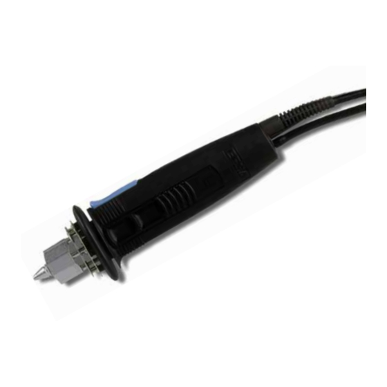
Inhaltsverzeichnis Contents Einführung Introduction Technische Daten Technical Data Sicherheitshinweise Safety information Inbetriebnahme Commissioning Funktionsbeschreibung Functional description Fehlerdiagnose und Error diagnosis and Fehlerbehebung Remedy Wartung und Maintenance Instandhaltung Ersatzteile und Spare parts and Bestelldaten ordering information Garantie Warranty... - Page 3 11. Vacuum hose 4. DIG 2000 or MIC 60 iA DIG 2000 oder MIC 60 iA 12. Vorfilter control unit 12. Prefilter 5. Fingertaster 5. Finger button 6. Entlötkolben X-Tool 6. X-Tool desoldering iron 7. Restlotbehälter 7. Residual solder container...
- Page 4 11. Vacuum hose 4. DIG 2000 or MIC 60 iA DIG 2000 oder MIC 60 iA 12. Vorfilter control unit 12. Prefilter 5. Fingertaster 5. Finger button 6. Entlötkolben X-Tool 6. X-Tool desoldering iron 7. Restlotbehälter 7. Residual solder container...
- Page 5 X-Tool Abbildungen X-Tool Pictures Abb. 2/Fig. 2 Dichtstopfen hinten Lotsammelfilter Solder collection filter Back sealing plug Partikelfilter Dichtstopfen vorne Front sealing plug Particle filter Restlotbehälter Residual solder container...
- Page 6 / white-green Heizkörper/ blau / blue heating element Ausschnitt X-Tool ohne Griffschale 2 und ohne Lottauffangbehälter / Cut-away of X-Tool with- out handle shell 2 and without solder collection container Ansicht Y / View Y blau / blue schwarz / black...
- Page 7 X-Tool Abbildungen X-Tool Pictures Abb. 4 a/Fig. 4 a Arretierknopf Gehäuseschraube Griffhälfte Entlötkopf Entlötspitze Locking knob Housing screw Handle half Desoldering head Desoldering tip Abb. 4 b/Fig. 4 b Ventil Arretierknopf Flachsteckverbindungen Ventilstößel Leiterplättchen Heizelemente Valve Locking knob Tab connectors...
-
Page 8: Einführung
Einführung Introduction Herzlichen Glückwunsch zum Erwerb dieser Congratulations on purchasing this high-tech High-Tech Entlötstation von ERSA. ERSA desoldering station. Sie verwenden diese Gerätekombination vorzugs- We recommend that you use this combination weise zum Entlöten bedrahteter Bauelemente unit for desoldering wired-up components aus einseitigen, doppelseitigen oder Multilayer- comprising single-sided, double-sided or multiple- Printplatten. - Page 9 • Mains lead • Vorfilter • Prefilter • Ablageständer mit Viskoseschwamm • Holder with viscose sponge • Entlötkolben X-Tool • X-Tool desoldering iron • Reinigungsnadel • Cleaning needle • Ersatz-Restlotbehälter komplett • Spare residual solder container, compl. • Lotsammelfilter 10 Stk.
-
Page 10: Technische Daten
Technische Daten Technical Data Kompressorstation CU 100 A Compressor Unit CU 100 A Spannung/Leistung: Voltage/Power: 230 V~, 50 Hz, 45 W; 115 V~, 60 Hz, 50 W 230 V~, 50 Hz, 45 W; 115 V~, 60 Hz, 50 W Beachten Sie bitte die Angaben auf dem Please refer to the information on the Leistungsschild! rating plate. - Page 11 Technische Daten Technical Data Entlötgerät X-Tool X-tool desoldering device Spannung: 24 V~ Voltage: 24 V~ Anheizleistung: 260 W Heat up rating: 260 W Anheizzeit: spitzenabhängig Heat up time: tip-dependent Gewicht (inkl. Kabel und Spitze): ca. 240 g Weight (incl. cable and tip): approx. 240 g Heizelemente: zwei Stück à...
-
Page 12: Sicherheitshinweise
Sicherheitshinweise Safety information Bitte beachten Sie vor der Inbetriebnahme Before commissioning, be sure to note the unbedingt beiliegenden Sicherheitshin- enclosed safety information. weise. -
Page 13: Inbetriebnahme
Inbetriebnahme Commissioning Compressor Unit CU 100 A Compressor Unit CU 100 A • Netzschalter auf 0 stellen. • Set the power switch to 0. • Vorfilter (Abb.1/Pos. 13) auf den Vakuuman- • Firmly connect the prefilter (fig. 1/no.13) onto schluß (VAC) der Pumpeneinheit CU 100 A the vacuum connection (VAC) of the CU 100 A fest aufstecken. - Page 14 Inbetriebnahme Commissioning 4.4 Entlötkolben X-Tool 4.4 X-Tool desoldering iron • Prüfen Sie, ob der Lotsammelfilter (Abb. 2/ • Check that the solder collection filter (fig. 2/ Pos.4) sowie der Partikelfilter (Abb. 2/Pos. 2) no. 4)and the particle filter (fig. 2/no. 2) are im Restlotbehälter (Abb.
- Page 15 Inbetriebnahme Commissioning 4.5 Einschalten 4.5 Switching on • Netzstecker (Abb. 1/Pos. 3) in die • Plug in the mains plug (fig. 1/no. 3) in the Compressor Unit CU 100 A bzw. die CU 100 A Compressor Unit respectively Venturi Unit VU 100 A und in die entspre- VU 100 A Venturi Unit, and into the chende Regeleinheit einstecken.
-
Page 16: Funktionsbeschreibung
Funktionsbeschreibung Functional description 5.1 Auswahl der richtigen 5.1 Selecting the correct desoldering Entlöttemperatur temperature Wählen Sie stets die niedrigstmögliche Entlöt- Always select the lowest possible desoldering temperatur für Ihre Aufgabe. Zu hohe Temperatu- temperature for your job. Excessively high tem- ren schädigen die Leiterplatte und die Bauteile. - Page 17 Funktionsbeschreibung Functional description 5.3 Wechseln der Entlötspitze 5.3 Changing the desoldering tip Die Entlötspitze (Abb. 4/Pos. 5) kann mit Hilfe The desoldering tip (fig. 4/no. 5) can be des am Ablageständer befindlichen Spitzen- changed using the tip holder fitted onto the halters gewechselt werden.
-
Page 18: Fehlerdiagnose Und
Fehlerdiagnose Error Diagnosis und -behebung and Remedy Entlötleistung ungenügend 6.1 Inadequate desoldering power siehe Kap. 7.1 - „Filter“ see chap. 7.1 - „Filters“ 6.2.1 Pumpe der CU 100 A läuft 6.2 CU 100 A pump starts up häufig an frequently Vakuumsystem ist undicht. - Page 19 Fehlerdiagnose Error Diagnosis und -behebung and Remedy 6.3.3 VU 100 A schaltet überhaupt nicht. 6.3.3 VU 100 A does not switch at all. Kein Vakuum vorhanden. No vacuum. Stromversorgung unterbrochen. Sicherung unter- No power supply. Check fuse below the power halb des Geräteanschlußsteckers auf der Rück- plug at the unit‘s rear side.
- Page 20 Fehlerdiagnose Error Diagnosis und -behebung and Remedy 6.4.1 Prüfung der Heizelemente 6.4.1 Testing the heating elements Wird die Entlötspitze nicht heiß, obwohl die Regel- Check both heating elements (fig. 5/no. 3) if the einheit offensichtlich funktioniert, so sollten die desoldering tip does not get hot despite the fact beiden Heizelemente (Abb.
- Page 21 Fehlerdiagnose Error Diagnosis und -behebung and Remedy 6.4.2 Prüfung des 6.4.2 Testing the Thermoelementfühlers thermocouple sensor Wird bei heißer Entlötspitze in der Istwertanzei- An indication of a defect in the thermocouple ge der Regelungseinheit nur eine niedrige, z.B. is that only a low temperature, e.g. room tem- Raumtemperatur, angezeigt, deutet dies auf ein perature, is shown on the actual value display of defektes Thermoelement hin.
- Page 22 Fehlerdiagnose Error Diagnosis und -behebung and Remedy • Öffnen Sie das Gehäuse (2 Schrauben auf Front- • Use a size 6 Torx driver to open the housing seite, 2 Schrauben im Gehäuseoberteil (Abb.4/ (2 screws on the front panel, 2 screws on the top Pos.
-
Page 23: Wartung Und Instandhaltung
(fig. 4/no. 1) holding the valve tappet (fig. 4/ stößel (Abb. 4/Pos. 4) hält, eingerastet ist. Eine no. 4) clips in. A spring in the X-Tool handle Feder im X-Tool Griff drückt den Restlotbehälter presses the residual solder container (fig. 2) out (Abb. - Page 24 Wartung und Maintenance Instandhaltung Vorsicht! Caution! Wenn Sie den Restlotbehälter während des If you remove the residual solder container Betriebes entnehmen, wird die Vorderseite, whilst you are using the unit, the front end of welche mit der Spitze in Berührung stand, the container - which was in contact with the noch heiß...
- Page 25 Wartung und Maintenance Instandhaltung 7.1.3 Wechseln des Partikelfilters 7.1.3 Changing the particle filter Der Partikelfilter (Abb. 2/Pos. 2) dient dazu, das The particle filter (fig. 2/no. 2) is used for pro- dahinterliegende Ventil (Abb. 4/Pos. 1) sowie tecting the downstream valve (fig. 4/no. 1) as Schläuche und Pumpe vor den Lötdämpfen zu well as the hoses and the pump against solder schützen.
- Page 26 Wartung und Maintenance Instandhaltung 7.1 Wichtige Pflegearbeiten 7.1 Important care jobs Hinweis: Note: Verwenden Sie ausschließlich Original ERSA Only use genuine ERSA consumables and Verbrauchs- und Ersatzteile, um sichere Funk- spare parts in order to ensure reliable function tion und Gewährleistung zu erhalten! and to maintain the unit‘s warranty.
- Page 27 Wartung und Maintenance Instandhaltung • Achten Sie darauf, dass Lüftungsöffnungen • Make certain that the effectiveness of the nicht durch Staubablagerungen ihre Wirkung ventilation holes is not impaired by a verlieren. build-up of dust. • Reinigen Sie mit dem im Zubehör befind- •...
-
Page 28: Ersatzteile Und Bestelldaten
CU 103 A Compressor unit for CU 100 A, CU 103 A CU 100 A, antistatisch antistatic Entlötkolben X-Tool mit Entlöt- X-Tool desoldering iron with de- 720 EDJ 720 EDJ spitze 722ED12, antistatisch soldering tip 722ED12, antistatic Heizeinsatz für X-Tool... - Page 29 Venturistation VU 103 A VU 103 A Venturi station VU 103 A VU 103 A für VU 100 A for VU 100 A X-Tool X-Tool ERSADUR desoldering tips ERSADUR-Entlötspitzen 722 EN 0818 722 EN 1529 722 EN 0823...
-
Page 30: Warranty
10. Garantie Warranty © 10/2004, ERSA GmbH • 3BA00062-00_01 ERSA hat diese Bedienungsanleitung mit großer Sorg- ERSA has produced these Operating Instructions with the utmost care. Nevertheless, we cannot provide any falt erstellt. Es kann jedoch keine Garantie in bezug auf Inhalt, Vollständigkeit und Qualität der Angaben in dieser guarantee regarding the content, completeness or qua- Anleitung übernommen werden.
Need help?
Do you have a question about the X-Tool and is the answer not in the manual?
Questions and answers