Advertisement
Quick Links
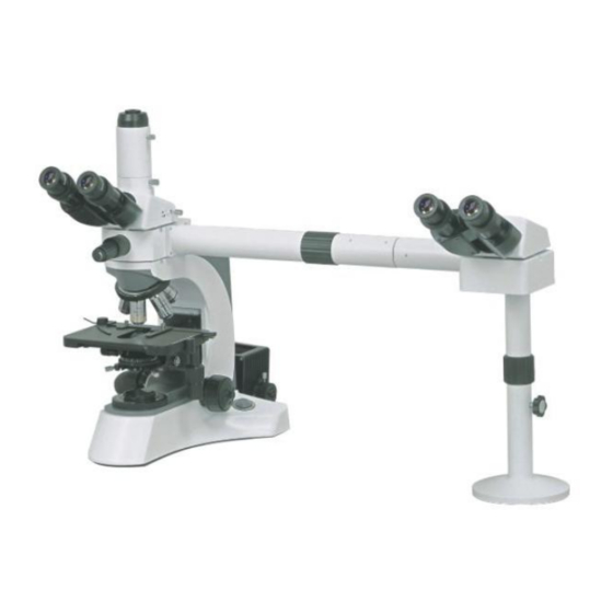
Set-up on a sturdy, level surface with a minimum space requirement of 18 x 36 inches
Tools required: Bubble level
1. Attach the primary dual viewing head attachment to the microscope frame. Then assemble the
microscope as described in the enclosed instruction booklet. The assembly includes the objectives,
viewing head, eyepieces lamp house and the stage/condenser assembly. Ensure the microscope is
operating properly.
2. Attach the longer of the two extension tubes to the primary dual viewing head attachment (A-1 to
A-1, Figure 1).
3. Place the secondary viewing head attachment/viewing head support column assembly on the right
side of the primary microscope. Attach the shorter of the two extension tubes to the secondary
viewing attachment (A-3 to A-3, Figure 2).
4. Connect the two extension tubes A-2 to A-2 (Figure 3).
5. Place a bubble level on the rear portion of the secondary viewing head attachment. The height of
the pole is adjusted by first loosening the black knob. Then rotate the lower portion of the support
column until the bubble is centered inside the level. Retighten the black knob.
6. Attach the secondary viewing head and insert the two eyepieces.
Operation of the illuminated pointer:
1. The pointer position is regulated be manipulating the pointer control lever.
2. The illumination intensity is adjusted by rotating the knob at the front of the pointer control lever.
3025-2 Microscope
SUPPLEMENTAL INSTRUCTIONS
Advertisement

Related Manuals for Accu-Scope 3025-2


Summary of Contents for Accu-Scope 3025-2
- Page 1 3025-2 Microscope SUPPLEMENTAL INSTRUCTIONS Set-up on a sturdy, level surface with a minimum space requirement of 18 x 36 inches Tools required: Bubble level 1. Attach the primary dual viewing head attachment to the microscope frame. Then assemble the microscope as described in the enclosed instruction booklet. The assembly includes the objectives, viewing head, eyepieces lamp house and the stage/condenser assembly.
- Page 2 ILLUMINATED POINTER CONTROL LEVER Figure 1 SECONDARY DUAL VIEWING HEAD ATTACHMENT VIEWING HEAD SUPPORT COLUMN ROTATING SECTION TO ADJUST HEIGHT Figure 2 SECONDARY DUAL PRIMARY DUAL VIEWING VIEWING HEAD HEAD ATTACHMENT ATTACHMENT Figure 3...