Table of Contents
Advertisement
Quick Links
Advertisement
Table of Contents

Related Manuals for Eickemeyer LifeVet CP


Summary of Contents for Eickemeyer LifeVet CP
-
Page 2: Product Information
Product Information • Product Model: LifeVet CP • Product Name: Capnograph and Pulse Oximeter • Manufacturer: EICKEMEYER KG • After-service Contact Information: Address: Eltastraße 8, 78532 Tuttlingen, Germany Phone: +49 7461 96 580 0 Fax: +49 7461 96 580 90 Email: info@eickemeyer.de... - Page 3 Statement Manufacturer holds the copyright of this manual, and we are also entitled to deal with this manual as confidential files. This manual is only used for operation, maintenance and service of product, someone else can not publish the manual. This manual contains exclusive information protected by copyright laws and we reserve its copyright.
-
Page 4: About This Manual
About this manual This manual contains the instructions necessary to operate the product safely and in accordance with its function and intended use. Observance of this manual is a prerequisite for proper product performance and correct operation and ensures patient and operator safety. This manual is based on the maximum configuration and therefore some contents may not apply to your product. - Page 5 Signs in this manual: Warning: Indicates a potential hazard or unsafe practice that, if not avoided, will result in death or serious injury. Caution: Indicates a potential hazard or unsafe practice that, if not avoided, could result in minor personal injury or product/property damage. Note: Provides application tips or other useful information to ensure that you get the most from your product.
-
Page 6: Table Of Contents
Contents Chapter 1 General Introduction ......... 1-1 Intended Use ............1-1 Main Unit ..............1-1 Display Views ............1-6 Chapter 2 Safety ..............2-1 Safety Information ..........2-1 Explanation of Symbols .......... 2-5 Chapter 3 Basic Operations ..........3-1 Unpacking and Checking ........3-1 Getting Started ............ - Page 7 Alarm Categories ............ 4-1 Alarm Levels ............4-2 Alarm Indicators ............. 4-3 Alarm Status Symbol ..........4-6 Alarm Tone Configuration ........4-6 Pausing Alarms ............4-7 Shutting off the Alarm Volume ........ 4-8 Alarm Reset ............4-9 When an Alarm Occurs ........... 4-9 Chapter 5 Measuring CO2 ..........
- Page 8 Monitoring Procedure ..........6-4 SpO2 Display ............6-5 PR Display .............. 6-6 Setting SpO2 ............6-7 Setting Desat Limit ..........6-8 Chapter 7 Trend Review ............. 7-1 Introduction ............7-1 Review Interface ............. 7-1 Review Setup ............7-2 Chapter 8 Battery ..............8-1 Introduction ............
- Page 9 Appendix A Product Specifications ........1 Safety Specifications ............ 1 Physical Specifications ..........1 Environmental Specifications........2 Charging Specifications ..........2 Hardware Specifications ..........3 Data Storage ..............4 Measurement Specifications ........5 Appendix B Factory Defaults ..........9 Alarm Setup ..............9 System Setup ..............
-
Page 10: Chapter 1 General Introduction
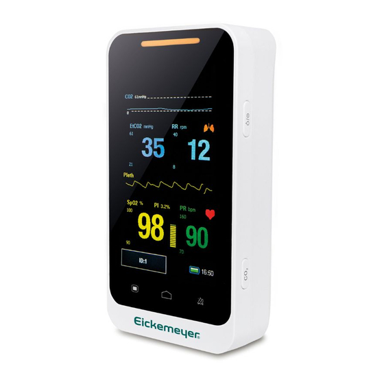
LifeVet CP User Manual Chapter 1 General Introduction Intended Use LifeVet CP patient monitor is intended for continuously monitoring or spot checking of CO2, RR, SpO2 and PR signals in animals. This device can be used in institutions or units with health care capability. - Page 11 LifeVet CP User Manual Fig 1-1 Front View of the Monitor Alarm indicating lamp When an alarm occurs, this lamp will light up as defined below: • High level alarm: the lamp quickly flashes red. • Medium level alarm: the lamp slowly flashes yellow.
-
Page 12: Rear View
LifeVet CP User Manual The device uses resistive touchscreen, using stylus or fingernail will improve sensitivity. Alarm pause button • It can pause the alarm for 120s when alarm volume is • Pressing it can change the alarm message to prompt message when “Sensor off”... - Page 13 LifeVet CP User Manual Fig 1-2 Rear View of the Monitor Side View Topside:...
- Page 14 LifeVet CP User Manual Downside: Rightside: Fig 1-3 Side View of the Monitor CO2 connector SpO2 probe connector Micro USB connector • Connect with power adapter. Shortcut key Press this button to start or pause the CO2 measurement. Power buttom •...
-
Page 15: Display Views
LifeVet CP User Manual • Press it about two seconds to turn off when the monitor is on the condition of working. • Calibration of touch screen Press shortcut key firstly and press power button and immediately loose shortcut key, click the center of appearing point on screen. - Page 16 LifeVet CP User Manual Multi-Parameter Display Mode Fig 1-4 Multif-parameter Display Mode Patient ID No.: Click and set patient information, its range from 1 to 96. SpO2 parameter area: The current SpO2 and its higher and lower alarm limits are shown in the area.
- Page 17 LifeVet CP User Manual CO2 parameter area: The current CO2 and its higher and lower alarm limits are shown in the area CO2 waveform area: CO2 waveform is shown in the area. Physiological alarm area: Current physiological alarm information is shown in the area.
- Page 18 LifeVet CP User Manual SpO2 Display mode Fig 1-5 SpO2 Display Mode SpO2 waveform area: The waveform shown in the area is current SpO volume curve. parameter area: The values shown in the area are current SpO value and its higher and lower alarm limits.
- Page 19 LifeVet CP User Manual CO2 Waveform Display Mode Fig 1-6 CO2 Display Mode CO2 waveform display area: Waveform shown in the area is current CO2 waveform 。 CO2 parameter area: The values shown in the area are current HR value and its higher and lower alarm limits.
-
Page 20: Chapter 2 Safety
LifeVet CP User Manual Chapter 2 Safety Safety Information Warning: • Explosion hazard: Do not use the monitor in the presence of flammable anesthetics mixture with air, oxygen, or hydrogen. • When the monitor is in use, there should not be any... - Page 21 LifeVet CP User Manual • Do not come into contact with the patient during defibrillation. Otherwise serious injury or death could result. • When the monitor is connecting with high-frequency devices, sensors and cables should avoid touching high-frequency devices, in order to leakage current burns patient.
- Page 22 LifeVet CP User Manual degrade or contamination could occur. • At the end of its service life, the product described in this manual, as well as its accessories, must be disposed of in compliance with the guidelines regulating the disposal of such products. If you have questions concerning disposal of products, please contact manufacturer or its representatives.
- Page 23 LifeVet CP User Manual unable to be connected to the AC power, the battery can be used to supply power, and at this time it is unnecessary to use the electrical wires, and the instrument can be switched on directly.
-
Page 24: Explanation Of Symbols
LifeVet CP User Manual • This manual describes all features and options. Your monitor may not have all of them. Explanation of Symbols Symbol Symbol Note Type CF applied part, defibrillation protected The unit displaying this symbol contains an F-Type... - Page 25 LifeVet CP User Manual Alarm reset QRS volume off Date of manufacture Manufacturer Serial number Power button Short for “Carbon dioxide” Short for “Respiratory Rate” Short for “Pulse Oxygen Saturation” Symbol for the marking of electrical and electronics devices according Directive 2002/96/EC.
-
Page 26: Chapter 3 Basic Operations
LifeVet CP User Manual Chapter 3 Basic Operations Unpacking and Checking Open the package. Parts are as follows in the package .Take out the monitor and its accessories. Parts Standard Optional Quantity CO2 nose sampling √ tube √ CO2 filter √... -
Page 27: Starting The Monitor
LifeVet CP User Manual following checks on the monitor including all connected modules. ——Check for any mechanical damage; ——Check for any incorrect connection of all the external cables and accessories Warning: • If the monitor is mechanically damaged, or if it is not working properly, do not use it for any monitoring procedure on a patient. -
Page 28: Screen Brightness Setting
LifeVet CP User Manual Screen Brightness Setting 【Menu】→【System】 ,click the right of 【Brightness】 , you can set the screen brightness to a value between 1to 5, choose the low level brightness to save power. Caution: If the monitor is used outdoors or the ambient light is strong, set the screen brightness to a higher level. -
Page 29: Patient Information Setting
LifeVet CP User Manual Select 【 Date Format 】 , it can be set to 【 Year/Month/Day 】 、 【 Month/Day/Year 】 or 【Day/Month/Year】. Select 【 Time Format】 , it can be set to 【24h】 or 【12h】 . Set the current date and time and select【OK】to confirm... -
Page 30: Demo Mode Setting
LifeVet CP User Manual Demo Mode Setting To enter the demo mode: Select 【Menu】→【System】→【Maintenance】→enter the required password. Click the right of 【Demo】to turn on. To exit the demo mode: Select 【Menu】→【System】→【Maintenance】→enter the required password. Click the right of 【Demo】to turn off. -
Page 31: Checking The Version
LifeVet CP User Manual Checking the Version Select【Menu】→【System】to check the version of the monitor . Restoring the Factory Configuration If you have changed the system’s configuration and want to restore the factory configuration, follow this procedure: Select【Menu】→【System】. 2. Selec【 t Set to Default】 , popping up a confirming window, select【OK】to restore the factory configuration. - Page 32 LifeVet CP User Manual 【System】→【Maintenance】, enter the required password, click the right of 【Auto power-off setting】, you can select “off”, “10min”, “30min”.
-
Page 33: Chapter 4 Alarm
LifeVet CP User Manual Chapter 4 Alarm Alarm refers to a prompt that is given by the monitor for medical personnel through visual, audible and other means when a vital sign appears abnormal or the monitor occurs technical problem. Note: The monitor generates all the audible and visual alarms through speaker, alarm lamp and screen. -
Page 34: Alarm Levels
LifeVet CP User Manual Technical alarms Technical alarms are triggered by a device malfunction or a patient data distortion due to improper operation or system problems. Technical alarm messages are displayed in the technical alarm area. Prompt messages As a matter of fact, prompt messages are not alarm messages. -
Page 35: Alarm Indicators
LifeVet CP User Manual Indicate that the patent’s vital signs appear abnormal and an immediate treatment may be required. By severity, the monitor’s technical alarms can be classified into four categories: high level, medium level alarms, low level alarms and prompt message. - Page 36 LifeVet CP User Manual screen. • Flashing numeric: The numeric of parameter in alarm flashes. Caution: For different alarm levels, the alarm lamp, alarm tone and alarm messages presented are different. Alarm Tone The different level alarms are indicated by the system in...
-
Page 37: Alarm Message
LifeVet CP User Manual following different visual ways: Alarm level Visual prompt High Alarm lamp flashes in red with 2 Hz. Medium Alarm lamp flashes in yellow with 0.5 Hz. Alarm lamp lights on in yellow without flashing. Caution: •... -
Page 38: Alarm Status Symbol
LifeVet CP User Manual Medium level alarms: ** Low level alarms: * ◆ The system uses different background colors for the alarm message to match the alarm level: High level alarms: red Medium level alarms: yellow Low level alarms: yellow... -
Page 39: Pausing Alarms
LifeVet CP User Manual Select 【Menu】→【System】→【Maintenance】, enter the required passwo d, select 【Machine Mainten.】 → 【Alarm Setup】→【Min.Alm.Vol.】, you can select “ Off, High, Mid, Low”. Alarm volume setting Select 【Menu】→【System】→【Alarm Volume】, you can select from X to 4. X indicates the minimum alarm volume. -
Page 40: Shutting Off The Alarm Volume
LifeVet CP User Manual Shutting off the Alarm Volume Set the 【Min.Alm.Vol.】 and【Alarm Volume】 to 【off 】 to shut off the alarm volume. Then there will be a symbol shown in the alarm status area. The alarm lamp and alarm messages are still active after the alarm volume is off. -
Page 41: Alarm Reset
LifeVet CP User Manual Alarm Reset Select 【Menu】→【System】→【Maintenance】→enter the required passwo d, select 【Machine Mainten.】 → 【Alarm Setup】. You can turn on alarm reset. Alarm reset will be displayed on the interface of system. Select 【Menu】→【System】→【Alarm reset】. After licking alarm reset •... - Page 42 LifeVet CP User Manual Identify alarming parameter and alarm category. Identify the cause of the alarm. Silence the alarm, if necessary. When cause of alarm has been over, check that the alarm system is working properly. You will find the alarm message for the individual parameter in Appendix C Alarm message.
-
Page 43: Chapter 5 Measuring Co2
LifeVet CP User Manual Chapter 5 Measuring CO2 Introduction The monitor adopts infrared absorption technology to measure the carbon dioxide (CO ) concentration in the breathing airway of patient. Because CO molecule can absorb infrared light of special wavelength, and the amount of absorbed infrared light directly... -
Page 44: Monitoring Procedure
LifeVet CP User Manual manner that may cause entanglement or strangulation. • Performance is not guaranteed if an item labeled as single patient use is reused. • Monitor the CO waveform (Capnogram). If you see changes or abnormal appearance check the sampling tube. - Page 45 LifeVet CP User Manual CO2 filter with 3-way joint of the loop of anesthetic machine by sampling tube, or to directly connect patient’s nose by the hose. Fig 5-1-1 Connection of Sampling and Filter...
- Page 46 LifeVet CP User Manual Fig 5-1-2 Connection of Sampling with 3-way joint or patient’s nose Note: • Inserting the sampling tube into the receptacle automatically starts the sampling pump. Removal of the sampling tube turns the sample pump off. •...
- Page 47 LifeVet CP User Manual Connect CO2 filter into CO2 connector and rotate CO2 filter closewise. Connect sampling tube into CO2 filter. If the sampling tube is occluded or damaged, perform a “Check sampling line” on screen.. Ensure that the CO2 sensor exhaust tube vents gases away from the sensor environment.
-
Page 48: Co2 Display
LifeVet CP User Manual CO2 Display • CO2 parameter display Fig 5-2 CO2 Display 1.CO2 label 2.CO2 high alarm limit 3. CO2 low alarm limit 4. CO2 value 5. CO2 unit • CO2 waveform display Fig 5-3 CO2 Waveform Display... -
Page 49: Respiratory Rate
LifeVet CP User Manual Respiratory Rate Fig 5-4 RR Display 1. RR label 2. RR higr alarm limit 3. RR low alarm limit 4. RR value 5. RR unit Setting CO2 Select 【Menu】→【CO2 Setup】, enter into CO2 setup interface. - Page 50 LifeVet CP User Manual Fig 5-5 CO2 Setup Interface Setting CO2 and RR Alarm Click the right of 【Alarm】, you can set CO2 and RR Alarm , you can select “Mid, High”. Setting CO2 and RR Alarm Limits Click the right of 【Uplimit】 or 【Downlimit】 , you can set...
- Page 51 LifeVet CP User Manual alarm limit should greater than the lower one. Setting CO2 Scan Speed Select scan speed of CO2 waveform. Click the right of 【Speed】, you can select “6.25 mm/s、12.5mm/s, 25 mm/s”. Setting CO2 Unit Click the right of【CO2 Unit】 , you can select “mmHg、 %、...
-
Page 52: Co2 Zero
LifeVet CP User Manual CO2 Zero While zeroing is recommended the first time the monitor is connected to the filter, it is only absolutely necessary when the message “Zero Required” is displayed. Follow these steps: Ensure that the sampling tube is not connected to the... -
Page 53: Calibration
LifeVet CP User Manual allows any CO2 remaining in the sampling tube to dissipate before zeroing. • Do not attempt to zero the monitor while the sampling tube is in the patient’s airway. • Do not attempt zeroing if the temperature is not stable. -
Page 54: Removing Exhaust Gases From The System
LifeVet CP User Manual ——After the latest calibration, atmospheric pressure or height above sea level varies evidently. Caution: User may only calibrate the device under the instruction of the technical personnel authorized by manufacturer. Moreover, incorrect calibrating procedure may result in incorrect reading. -
Page 55: Chapter 6 Measuring Spo2
LifeVet CP User Manual Chapter 6 Measuring SpO2 Introduction The measurement of oxygen saturation of arterial blood (also known as pulse oxygen saturation, usually shortened as ) adopts the principles of light spectra and volume tracing. The LED emits lights with two specific wavelengths, which are... -
Page 56: Safety Information
LifeVet CP User Manual Safety Information Warning : • Use only SpO2 sensors specified in this manual. Follow the SpO2 sensor’s instructions for use and adhere to all warnings and cautions. • When a trend toward patient deoxygenation is indicated, blood samples should be analyzed by a laboratory co-oximeter to completely understand the patient’s conditions. - Page 57 LifeVet CP User Manual errors, and certain patient conditions. See the appropriate sections of this manual for specific safety information. • Check the SpO2 sensor and its package for any sign of damage before use. Do not use the sensor if any damage is detected.
-
Page 58: Monitoring Procedure
LifeVet CP User Manual examination alarm signal and the operator has to use simulator for self-examination. Monitoring Procedure 1. Selecting SpO Sensor Depending on the patient category, weight and application site, you can select the SpO sensor as required. 2. Connecting SpO2 Sensor... -
Page 59: Spo2 Display
LifeVet CP User Manual cuff is applied. This may result in inaccurate SpO2 reading due to blocked blood flow during cuff inflation. • Do not conduct SpO2 measurement on the finger smeared with nail polish, otherwise unreliable measurement results might be produced. -
Page 60: Pr Display
LifeVet CP User Manual • Waveform Display Fig 6-2 SpO Volume Curve PR Display Fig 6-3 PR Display 1. PR label 2. High alarm limit of PR 3. Low alarm limit of PR 4. PR value 5. PR unit... -
Page 61: Setting Spo2
LifeVet CP User Manual Caution: During the monitoring of HR and PR, displaying of HR has priority. That is PR will be displayed only when there isn’t HR monitoring. Setting SpO2 Select 【Menu】→【SpO2 Setup】, enter into SpO2 Setup interface. Fig 6-4 SpO2 Setup... -
Page 62: Setting Desat Limit
LifeVet CP User Manual Setting SpO2 Alarm Click the right of 【Alarm】 , you can set alarm level of SpO and PR, you can select “Mid, High” Setting SpO2 Alarm Limits Click the right of 【Uplimit】 or 【Downlimit】 , you can set the SpO2 uplimit and downlimit. - Page 63 LifeVet CP User Manual the desat limit, a high physiological alarm will be trigged. Its setting is as follows. 1、 Select 【 Menu】 → 【System】 → 【Maintenance】 , enter the required password. 2、 Select 【Machine Mainten】→【SpO2 Setup】→【Desat limit】, click the right of 【Desat limit】to set its value.
-
Page 64: Chapter 7 Trend Review
LifeVet CP User Manual Chapter 7 Trend Review Introduction Select 【Menu】→【Trend】to enter trend reviewing window. In the window, you can review CO2, RR, SpO and PR data stored before. Review Interface Fig 7-1 Review Interface... -
Page 65: Review Setup
LifeVet CP User Manual If the trend date is not only one page, you can turn pages by the next/return button. Review Setup Click the right of 【ID】to select patient’s ID, you can review patient’s trend review by selecting different ID. - Page 66 LifeVet CP User Manual Fig 7-3 The drop-down Window of “More” You can set 【Save time】, 【Delete】, 【Delete all】, 【Transmission】in this interface. • Save time: To adjust recording time, you can select”10s, 30s, 1min, 2 min, 5min, 10min”. • Delete: To delete trend data of the selected ID No.
-
Page 67: Chapter 8 Battery
LifeVet CP User Manual Chapter 8 Battery Introduction A rechargeable and maintenance-free battery is designed for Patient Monitor, which enables continuous working when AC power off. When r a lithium ion battery is used, the battery icon indicates the battery status as follows: Indicates that the power of the battery is full;... -
Page 68: Charging The Battery
LifeVet CP User Manual Charging the Battery To charge the battery: Connect the Micro USB in power adapter, Connect the other connector of Micro USB in the monitor, and plug the adapter into the AC mains, The indicating lamp on the monitor is on to indicate that... -
Page 69: Checking The Lithium Battery
LifeVet CP User Manual 2. Place the monitor in the charger stand and connect the AC mains. Allow the battery to be charged uninterruptedly for above 4 hours. 3. Remove the AC mains and allow the monitor to run from the battery until it shuts off. -
Page 70: Disposing Of The Batteries
LifeVet CP User Manual Disposing of the Batteries Batteries that are damaged or depleted should be replaced and discarded properly. Dispose of used batteries according to local regulations. Warning: Do not disassemble batteries, or dispose of them in fire, or cause them to short circuit. -
Page 71: Chapter 9 Maintenance And Cleaning
LifeVet CP User Manual Chapter 9 Maintenance and Cleaning Introduction Keep your equipment and accessories free of dust and dirt. To avoid damage to the equipment, follow these rules: Always dilute according the manufacturer’s instructions or use lowest possible concentration. -
Page 72: Seasonal Safety Checking
LifeVet CP User Manual Caution: If you spill liquid into the equipment of accessories, connect you service personal or us. Seasonal Safety Checking Note: To ensure the performance and safety of equipment, it must be checked after using 1 year. - Page 73 LifeVet CP User Manual instructions for use. ④ Test the earth leakage current according IEC 60601-1 Limit: NC 500μA, SFC: 1000μA. ⑤ Test the enclosure leakage current according to IEC 60601-1: Limit: NC 100μA, SFC: 500μA. ⑥ Test the patient leakage current (normal operation) according IEC 60601-1 Limit: type CF: for a.c.: 10μA, for d.c.: 10μA.
-
Page 74: Cleaning The Monitor
LifeVet CP User Manual Cleaning the Monitor Common detergent and non-corrosive disinfectant used in hospital can be applied to clean monitor, however you must be aware that many kinds of detergents must be diluted prior to utilization, and please use it according to the instruction of detergent manufacturer. -
Page 75: Cleaning Spo2 Sensor
LifeVet CP User Manual Cleaning SpO2 Sensor 1. The casing of the sensor and light tube can be cleaned with swab or non-velvet soft cloth dipped with medical alcohol. 2. The sensor cable can be cleaned or sterilized with Hydrogen Peroxide 3% or isopropyl alcohol 70%. -
Page 76: Chapter 10 Accessories
LifeVet CP User Manual Chapter 10 Accessories Warning: • Use only accessories specified in this manual. Using other accessories may cause damage to the monitor. • Disposable accessories are designed for single-patient use only. Reuse of them may cause a risk of contamination and affect the measurement accuracy. -
Page 77: Appendix A Product Specifications
LifeVet CP User Manual Appendix A Product Specifications Safety Specifications CFDA classification CE classification Type of protection against electric II, with internal power or shock external power device Degree of protection against electric shock Ordinary equipment, without Degree of protection against... -
Page 78: Environmental Specifications
LifeVet CP User Manual Environmental Specifications Operating: 5℃ to +40℃; Temperature Storage: -20℃ to +55℃; Operating: 860hPa to 1060hPa; Atmospheric Storage: 500hPa to 1060hPa; pressure Operating: 15% to 85%(non condensing) Humidity Storage: 10% to 93%(non condensing) Charging Specifications A4.1 Charger... -
Page 79: Hardware Specifications
LifeVet CP User Manual Hardware Specifications Display Size 4.3inch Resolution 480*272 Touch Resistive touch Autorotation four direction Direction Indicating Lamp Alarm indicating 1 (Yellow/Red), on the top of screen 1 (orange) Battery charging When charged, it lights orange. indicating lamp When fully charged or not charged, it doesn’t light. -
Page 80: Data Storage
LifeVet CP User Manual 60601-1-8. Alarm pressure 45 dB to 85 dB, Testing place is 1 meter from the tone. Buttons Power button Turn on/off Start/Pause CO2 measurement Short press to achieve the above function, Shortcut key long press + power button to achieve... -
Page 81: Measurement Specifications
LifeVet CP User Manual 500 groups/patient can be stored (only Capacity data, no waveform). Measurement Specifications CO2 Specifications CO2 (Sidestream) Measureme Infrared spectrum nt Way 0—19.7% (0-150mmHg or 0-20.0kPa ) Measureme nt Range 0%-5.3% (0mmHg-40mmHg),±0.3% (±2mm Hg); Accuracy 5.4%-9.2% (41mmHg-70mmHg), ±5% of reading;... - Page 82 LifeVet CP User Manual Unit %, mmHg, kPa Measureme 3~150 rpm nt Range of awRR Measuring ±1% or ± 1 rpm, whichever is greater accuracy of <3s Response Time Calibration Offset calibration, auto/ manual; gain calibration 0—19.7%( 0-150mmHg or 0-20.0kPa )
- Page 83 LifeVet CP User Manual range Resolution 70~100%:± 2% Accuracy Alarm Select the high and low alarm limit of Sensor Pulse oximetry sensors contain LEDs that emit red light at a wavelength of approximately 660 nm and infrared light at a wavelength of approximately 905 The total optical output power of the sensor LEDs is less than 15 mW.
- Page 84 LifeVet CP User Manual Pitch Tone with Measuremen 25 bpm ~250 bpm t range resolution 1 bpm accuracy ±1% or ± 1 bpm, whichever is greater Alarm Select the high and low alarm limit of PR...
-
Page 85: Appendix B Factory Defaults
LifeVet CP User Manual Appendix B Factory Defaults This section lists the most important factory default settings. These settings can be adjusted and you can load the factory defaults if you need. Alarm Setup Alarm Setup Factory Default Alarm volume... -
Page 86: Co2 Setup
LifeVet CP User Manual CO2 Setup CO2 setup Horse EtCO2 High Limit 62 mmHg 62 mmHg 62 mmHg EtCO2 Low Limit 21 mmHg 21 mmHg 21 mmHg Horse RR High Limit 35 rpm 40 rpm 40 rpm RR Low Limit... -
Page 87: Appendix C Alarm Message
LifeVet CP User Manual Appendix C Alarm Message This section lists some important alarm message. In the tables below, “*” means the alarm level is user-adjustable. Physiological Alarm SpO2 Cause Level Alarm Messages SpO2 Too High * High、 Medium A measurement has risen High、... -
Page 88: Technical Alarm
LifeVet CP User Manual weak to be analyzed. Cause Level Alarm Messages High、 EtCO2 Too High A measurement has risen above the high alarm limit Medium or fallen below the low EtCO2 Too Low * High、 alarm limit. Medium High、... - Page 89 LifeVet CP User Manual Sensor Off The CO sensor detached the patient or the monitor. Communication Communication error or test Error model error. Battery Low The battery power is low. Medium Low Perf The signal detected is weak. Medium measurement...
-
Page 90: Prompt Message
LifeVet CP User Manual Prompt Message Message Cause Level searching Searching pulse sensor off sensor may be disconnected from the Prompt patient or the monitor. Message Zero in Progress Zeroing is in progress. sensor off Sensor dose not connect with monitor when the monitor is running. -
Page 91: Appendix D Emc
LifeVet CP User Manual Appendix D EMC... -
Page 92: Appendix E Warranty Registration Card
® Thank you for purchasing EICKEMEYER products! Please complete this card and mail back to EICKEMEYER KG within one week. If you need any support or the defects occur, please feel free to contact us by telephone or fax. Warranty will apply with no charge in the warranty period (exclude accident, misuse, abuse or misapplication).
Need help?
Do you have a question about the LifeVet CP and is the answer not in the manual?
Questions and answers
We have received our new device today but it is stuck in German, when going into maintenance to change the language settings it asks for a password, we have not set a password up and do not know what it is