
Related Manuals for Eickemeyer MAGIC 6000


Summary of Contents for Eickemeyer MAGIC 6000
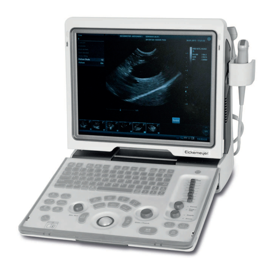
- Page 1 MAGIC 6000 ULTRASOUND UNIT USER MANUAL Art. No. 303720 TELEFON +49 7461 96580 0 www.eickemeyer.com...
-
Page 3: Table Of Contents
Contents Intellectual Property Statement ......................II Responsibility on the Manufacturer Party ..................II Warranty ............................III Exemptions ..........................III Customer Service Department ....................III Important Information ........................IV About This Manual ..........................V Notation Conventions ........................V Operator’s Manuals ........................... V Software Interfaces in this Manual .................... - Page 4 3.4.2 Disconnecting a Probe ....................3-4 Connecting the Footswitch ....................3-5 Connecting/ Removing a USB Storage Device ..............3-5 Graph / Text Printer ......................3-5 Digital Video Printer ......................3-7 Analog Video Printer ......................3-7 3.10 External DVD ........................3-8 3.11 Basic Screen and Operation ....................
- Page 5 Cine Memory ........................6-5 6.3.1 Cine Memory Setting ....................6-5 6.3.2 Cine Memory Clear ....................... 6-5 Preset ........................... 6-6 Measurement ....................... 7-1 Basic operations ........................7-1 General Measurements ......................7-1 7.2.1 2D General Measurements ..................7-1 7.2.2 M General Measurements .................... 7-2 Application Measurement .....................
- Page 6 9.7.4 Add/ Delete a User ..................... 9-16 9.7.5 Modify Password ......................9-18 10 DICOM ........................10-1 10.1 DICOM Preset ........................10-1 10.1.1 Network Preset ......................10-1 10.1.2 DICOM Preset ......................10-2 10.1.3 DICOM Service ......................10-4 10.2 Verify Connectivity ......................10-11 10.3 DICOM Service ........................
- Page 7 12.1.6 Storage and Transportation ..................12-10 12.2 Biopsy Guide ........................12-10 12.2.1 Basic Procedures for Biopsy Guiding ............... 12-12 12.2.2 Needle-guided Brackets ................... 12-13 12.2.3 Biopsy Preset ......................12-18 12.2.4 Needle-guided Bracket Inspection and Installation ..........12-19 12.2.5 Biopsy Menu ......................12-23 12.2.6 Verify Biopsy Guide Line...................
- Page 9 d. All rights Reserved. IMPORTANT! The system is veterinary use only. The label of veterinary information is adhered to the system. Please observe the instruction. The following label applies to U.S.A. only.
-
Page 10: Responsibility On The Manufacturer Party
Responsibility on the Manufacturer Party Contents of this manual are subject to change without prior notice. All information contained in this manual is believed to be correct. shall not be liable for errors contained herein or for incidental or consequential damages in connection with the furnishing, performance, or use of this manual. -
Page 11: Warranty
Warranty THIS WARRANTY IS EXCLUSIVE AND IS IN LIEU OF ALL OTHER WARRANTIES, EXPRESSED OR IMPLIED, INCLUDING WARRANTIES OF MERCHANTABILITY OR FITNESS FOR ANY PARTICULAR PURPOSE. Exemptions bligation or liability under this warranty does not include any transportation or other charges or liability for direct, indirect or consequential damages or delay resulting from the improper use or application of the product or the use of parts or accessories not approved or repairs by people other than authorized personnel. -
Page 12: Important Information
Important Information 1. It is the customer’s responsibility to maintain and manage the system after delivery. 2. The warranty does not cover the following items, even during the warranty period: (1) Damage or loss due to misuse or abuse. (2) Damage or loss caused by Acts of God such as fires, earthquakes, floods, lightning, etc. -
Page 13: About This Manual
About This Manual This operator’s manual describes the operating procedures for this diagnostic ultrasound system DP-50Vet and the compatible probes. To ensure safe and correct operations, carefully read and understand the manual before operating the system. Notation Conventions In this operator’s manual, the following words are used besides the safety precautions (refer to "Safety Precautions"). -
Page 14: Software Interfaces In This Manual
Software Interfaces in this Manual Depending on the software version, preset settings and optional configuration, the actual interfaces may be different from those in this manual. Conventions In this manual, these conventions are used to describe the buttons on the control panel, the items in menu, buttons in dialog box and some basic operations: <Buttons>: The angular bracket indicates buttons, knobs and other controls on control panel. -
Page 15: Safety Precautions
Safety Precautions Safety Classification According to the type of protection against electric shock: CLASS I EQUIPMENT According to the degree of protection against electric shock: Type-BF applied part According to the degree of protection against harmful ingress of water: Main unit: IPX0 Probes: IPX7 According to the degree of safety of application in the presence of a FLAMMABLE ANESTHETIC MIXTURE WITH AIR or WITH OXYGEN OR NITROUS OXIDE:... -
Page 16: Meaning Of Signal Words
Meaning of Signal Words DANGER WARNING CAUTION In this manual, the signal words" ”, “ ”, “ ”, “NOTE” and "Tips" are used regarding safety and other important instructions. The signal words and their meanings are defined as follows. Please understand their meanings clearly before reading this manual. -
Page 17: Safety Precautions
Safety Precautions Please observe the following precautions to ensure animal and operator’s safety when using this system. DO NOT use flammable gasses, such as anesthetic gas or DANGER: hydrogen, or flammable liquids such as ethanol, near this system, because there is danger of explosion. Do connect the power plug of this system and power plugs WARNING: of the peripherals to wall receptacles that meet the ratings... - Page 18 DO NOT allow the animal to contact the live parts of the ultrasound system or other devices, e.g. signal I / O ports. Electric shock may occur. Do not use an aftermarket probe other than those specified by . The probes may damage the system causing a profound failure, e.g.
- Page 19 Malfunctions due to radio wave: If a radio wave emitting device is used in the proximity of this system, it may interfere with operations. Do not bring or use devices that generate radio waves, such as cellular telephones, transceivers, and radio controlled toys, in the room where the system is installed.
- Page 20 The system and its accessories are not disinfected or sterilized prior to delivery. The operator is responsible for the cleaning and disinfection of transducers and sterilization of biopsy brackets according to the manuals, prior to the use. All items must be thoroughly processed to completely remove harmful residual chemicals, which will not only be harmful to the human body, but also damage the accessory.
- Page 21 NOTE: DO NOT use the system in the vicinity of strong electromagnetic field (such as a transformer), which may affect the performance of the system. DO NOT use the system in the vicinity of high-frequency radiation source, which may affect the performance of the system or even lead to failure. When using or placing the system, keep the system horizontal to avoid disbalance.
- Page 22 Please read the following precautions carefully to ensure the safety of the animal and the operator when using the probes. The ultrasonic probe is only for use with the specified WARNING: ultrasonic diagnostic system. Please refer to the “2.5.2 Probes Available” to select the proper probe. The ultrasonic probe must be used only by qualified professionals.
- Page 23 Disposable components are packaged sterile and are single-use only. Do not use if integrity of packaging violated or if expiration date has passed. Please use the disposable components compliant with the relevant local regulations. Please use the disinfection or sterilization solution that recommended in this operator’s manual, otherwise will not be liable for damage caused by other solutions.
-
Page 24: Latex Alert
NOTE: 1. The following definition of the WEEE label applies to EU member states only: The use of this symbol indicates that this system should not be treated as household waste. By ensuring that this system is disposed of correctly, you will help prevent bringing potential negative consequences to the environment and human health. -
Page 25: Warning Labels
Warning Labels The warning labels are attached to this system in order to call your attention to potential hazards. The symbol on the warning labels indicates safety precautions. The warning labels use the same signal words as those used in the operator’s manual. Read operator’s manual carefully before using the system. -
Page 27: System Overview
System Overview Intended Use The Digital Ultrasonic Diagnostic Imaging System is intended for use in abdomen, thoracic, cardiac, tendinous, small parts, ophthalmic, reproduction system exams for animals such as dog, cat, equine, bovine and ovine, etc. Contraindication None. Product and Model Code Model code Product code NOTE:... -
Page 28: Environmental Conditions
2.4.3 Environmental Conditions Operational Conditions Storage and Transportation Conditions Ambient temperature Relative 30% 85% (no condensation) 30% 95% (no condensation) humidity Atmospheric 700hPa 1060hPa 700hPa 1060hPa pressure Do not use this system in the conditions other than those WARNING: specified. 2.4.4 Size and weights Size: 190mm×415mm×378mm (Depth×Weight×Height) - Page 29 Region Probe Model Category Intended Use Applied Linear Small animal’s abdomen, small parts and 10L24EA Body surface array eyeball Linear Big animal’s reproductive system and Transrectal, 50L60EAV array tendon body surface Linear Big animal’s reproductive system and Transrectal, 75L50EAV array tendon body surface Some of the probes have matched needle-guided brackets for biopsy, the available probes...
-
Page 30: Options
2.5.3 Options Item iClear module IMT module DICOM basic module (including: task management, DICOM storage, DICOM print, DICOM storage commitment, DICOM media storage (including DICOM DIR) and etc.) DICOM worklist module (only can be applied with the DICOM basic function module configured) DVD R/W Drive: Model: SE-S224(USB port) -
Page 31: Introduction Of Each Unit
Introduction of Each Unit System Overview 2-5... - Page 32 Name Function Probe holder Used to place the probe Displays the image and parameters during scanning (tilt angle LCD Display adjustable) Control Panel Refer to the 2.6.3 Control Panel. Lock button (x2) Press to release the control panel while it’s folded Handle Used to carry the machine Interface panel used for inputting and outputting signals, refer...
-
Page 33: I/O Panel
2.6.1 I/O Panel <1> <2> <3> <4> <5> <6> <7> 3.3V <8> Symbol Function Network port USB ports Separate video output, connecting video printer or LCD Remote control port VGA signal output Composite video output Power indicator 2.6.2 Power Supply Panel <1>... -
Page 34: Control Panel
2.6.3 Control Panel Name Description Function Off: when system is turned off; Green: when system is turned on by pressing this Power button button; Orange: when system is in standby. Exit Press to exit the current status to the previous status. - Page 35 Name Description Function Alphanumeric Same as on PC keys Arrow Press to enter or exit the arrow comment status. Main menu Press to display or hide a mode-specific Menu parameter menu. Cine Cine Review Press to enter or exit the Cine Review status. Direction key To adjust LCD brightness or contrast when pressing with <Fn>...
- Page 36 Name Description Function Press to confirm an operation, same as the left- button of a mouse. Trackball Roll the trackball to change the cursor position. Press to confirm an operation, same as the left- button of a mouse. Freeze Press to freeze or unfreeze the image. Print Press to print: user-defined key.
-
Page 37: Symbols
Symbols This system uses the symbols listed in the following table, and their meanings are explained as well. Symbol Description Type-BF applied part General warning, caution, risk of danger Dangerous voltage Equipotentiality Power button Network port USB ports Video output Remote control port VGA signal output AC (Alternating current) -
Page 39: System Preparation
System Preparation Move/Posit the System Please read and understand the safety precautions before placing the system to ensure safety for both operator and devices. 1. Switch off the power, and pull out the plug. 2. Disconnect the system from all peripherals. 3. -
Page 40: Powering On/ Off
Powering ON/ OFF 3.3.1 Powering ON To ensure safe and effective system operation, you must CAUTION: perform daily maintenance and checks. If the system begins to function improperly – immediately stop scanning. If the system continues to function improperly – fully shut down the system and contact Customer Service Department or sales representative. -
Page 41: Powering Off
Check Item There shall no evident excessive noise, discontinuous, absent or black <3> artifacts in the B Mode image. Check if there is abnormal heat on the surface of the probe during an <4> ultrasound procedure. <5> The control panel keys and knobs are fully functional. The exam date and time are the same as the system date and time, and <6>... -
Page 42: Connecting / Disconnecting A Probe
Connecting / Disconnecting a Probe When connecting or disconnecting a probe, place it in a CAUTION: proper position, to prevent the probe from falling off or becoming damaged. Only use the probes provided by . Aftermarket probes may result in damage or cause a fire. 3.4.1 Connecting a Probe The probes, cables and connectors are in proper operating... -
Page 43: Connecting The Footswitch
Connecting the Footswitch Connect the footswitch to the main unit via a USB port. Set the functions of the footswitch in the [Key Config] page. Refer to "11.1.5 Key Config" for details. Connecting/ Removing a USB Storage Device DO NOT detach an USB storage device directly; WARNING: otherwise , the ultrasound system or the USB device and/ or data stored in the device may be damaged. - Page 44 (2) Select "Add Local Printer" and click [Next] to enter the screen of browsing driver, select the desired driver and click [OK] to install the driver. 5. Select the printer from the list and the “property” field displays the service, letter of this printer.
-
Page 45: Digital Video Printer
Digital Video Printer Install a local printer 1. Put the printer in a proper place. 2. Connect the printer (VIDEO IN port) and the ultrasound system (USB port) with the data cable. 3. Load a paper roll, and turn on the system and printer. 4. -
Page 46: External Dvd
3.10 External DVD 1. Connect the USB cable of the DVD recorder to the USB port on the ultrasound system (all USB ports available). 2. Connect the power adapter of the DVD on the power supply. 3.11 Basic Screen and Operation 3.11.1 Basic Screen The following diagram maps out the different areas in the screen: Hospital name... - Page 47 Exam time Displays the exam time, including date and time. Exam time can be set via [Setup]-> [System Preset]-> [Region]. Exam time will be frozen with the frozen image. Acoustic power & MI/TI Displays the acoustic power. Including the acoustic power, MI (Mechanical Index) and TI (Thermal Index).
- Page 48 Attribute tags of the item. Items Refers to the items on a menu. For item that is applicable for more than one mode, the item appears as universal item in the certain mode. Items of image modes and measurement can be preset (refer to "11 Setup" for details). Return to previous menu Click [Return] to return to the previous menu from the sub menu.
-
Page 49: Basic Operations Of Screens
Send to: select a thumbnail image , and click to send it to other devices. System status icon This area displays the relevant system icons, such as USB memory device, printer, network, Chinese / English entry, and current system time, etc. None-fixing Area Position of areas illustrated here are not fixed, you can move them by the trackball within a certain area on the display. - Page 50 Composition Description For some screens, contents are distributed across several pages. Use the selection pointer and <Set> key to Page Tab open/close the available pages. Use the selection pointer and [Set] key to open / close the available pages. Radio button: click to select the item. Check box: click to check or uncheck the item.
-
Page 51: Exam Preparation
Exam Preparation Before examining a new animal, press <End Exam> to end the CAUTION: exam of the previous animal, update the animal information, to avoid mixing data of the next new animal. Start an Exam You can start an animal exam in the following situations: New animal information: to start a new animal exam, enter the animal information first, for details, please refer to “4.2.1 New Animal Information”;... - Page 52 Place the cursor onto the targeted box. The field box is highlighted and a flashing cursor appears. Information can be entered or selected from the options. You can also change the cursor position by <Tab>, <Enter> or up/down controls Information includes: 1.
- Page 53 Or, click to select the date, and click [OK] to confirm. Auto generated age: once the DOB is gotten, the system can display an auto- generated age in the field box, the unit can be “Years”, “Months” or “Days”. If the age is less than one year, the system will automatically calculate the age in months or days.
- Page 54 Exam Type Information Description (Gynecology) Gravida Times of pregnancy. Para Times of delivery Ectopic Times of abnormal pregnancy. e.g. extrauterine pregnancy Aborta Times of abortion Height Weight BSA (body After the height and weight are inputted, the system will surface automatically calculate the BSA based on the formula which CARD area)
-
Page 55: Retrieve Animal Information
4.2.2 Retrieve Animal Information 4.2.2.1 iStation The animal data can be obtained in iStation from the system hardware or USB memory device. You can enter the searching conditions for the animal. 1. To enter iStation screen (the screen is shown as follows): Press <iStation>... - Page 56 Button Function Description Review Click to enter the Review screen. Image Patient Click to enter the Animal Info screen. Info Review Click to enter the Diagnostic Report screen. Report Delete Click to delete the selected record. Exam Backup Click to export the selected animal data to media supported. Exam Restore Click to import the animal data from an external media.
-
Page 57: Select Exam Mode And Probe
Or select the keyword type, enter the keywords and then click [Query] to search. To reset the criteria, click [Clear] button. 3. Select the desired animal from the list. Click [Start Exam], the animal information is imported into the system and then an exam is started. -
Page 58: Dual Probe Switching
(2) Roll the trackball and press <Set> to select the exam mode, and use the direction keys to turn pages of the exam modes. To save the image parameters for the current exam mode quickly: (1) Click [Save] to save the image parameters in the current image mode as presets. A dialogue box pops up to prompt you the operation will cover the current image preset data. -
Page 59: Bi-Plane Endocavity Probe (65Eb10Ea)
4.3.4 Bi-plane Endocavity Probe (65EB10EA) When active the probe, system displays sagittal plane B-mode image by default, you can switch the plane by clicking [Select Plane] on the menu to select the plane among S (sagittal) Plane, T (transverse) Plane. The S and T plane are shown visually on the right side of the screen. -
Page 60: End An Exam
1. Saves the exam-related images, reports and measurement data, modifies the status as Paused . 2. Save the exam information, including report, imaging mode, exam mode, image parameters, operation mode, imaging / measurement data and so on. 4.6.2 End an Exam Before examining a new animal, press <End Exam>... -
Page 61: Image Optimization
Image Optimization The images displayed in this system are only reference for WARNING: diagnosis. not responsible for the correctness of diagnostic results. It is the responsibility of the clinician, who performs the exam, to capture the correct diagnostic results. In Dual-B imaging mode, the measurement results of the merged image may be inaccurate. -
Page 62: B Mode
Requirement Available Operations Adjust [Dynamic Range] Adjust [Map] To modify gray scale image effect Adjust [Persistence] Adjust [iClear] (optional) Decrease [Depth] Decrease the [Focus Number] To increase frame Decrease the [FOV] rate Decrease [Line Density] Turn on [High FR] in harmonic mode Adjusting through Image Menu: Press <Menu>... -
Page 63: B Mode Image Optimization
Display F 2.5M D 21.3 G 100 FR 34 IP 1 DR 65 Parameter Frequency Depth Gain Frame Rate B IP B Dynamic Range Parameters that can be adjusted to optimize the B Mode image are indicated in the following. Adjustment Items Control Panel... - Page 64 Operation To increase the gain compensation at an area of interest, move the TGC slider to the right. To decrease the gain compensation at the corresponding area of interest, move the TGC slider to the left. About 1.5s after the adjustment is finished, the TGC curve disappears. Effects Adjust the signal gain for the certain image area to get a balanced image.
- Page 65 Operation Change the scan range through the [FOV] item in the menu; The system provided four levels of scan range: ExFOV, W, N, M1, M2. You can get a much larger field of view when selecting a larger FOV, but the frame rate will decrease.
- Page 66 Persistence Description This function is used to superimpose and average adjacent B images, so as to optimize the image and remove noises. Operation Adjust through the [Persistence] item in the menu; The system provides 8 level of frame average adjustment, the bigger the value the stronger the effect.
- Page 67 Operation Select among the maps through the [Gray Map] item in the menu; You can also adjust through the grayscale bar: move the cursor to the grayscale bar and press <Set> on the control panel to adjust. The system provides 8 gray maps to be selected among. Impacts The function is available in real-time imaging, freeze or cine review status.
-
Page 68: M Mode
Operation Click [Gray Rejection] in the menu to adjust. The adjusting range is 0-5. Curve Description To manually enhance or restrain the signal in the certain scale. Operation Click [Curve] in the menu to open the dialogue box to adjust. Drag the curve node to increase or decrease the gray scale information: drag the node up to increase the information and down to decrease. -
Page 69: M Mode Parameters
5. Adjust the image parameters to obtain optimized images. 6. Perform other operations (e.g. measurement and calculation) if necessary. 5.4.2 M Mode Parameters In M mode scanning, the image parameter area in the upper left corner of the screen displays the real-time parameter values as follows: Display IP 6 DR 65... - Page 70 Effects When time mark is displayed on the M mode image, it's much easier to identify the cardiac cycles and detect more details. Impacts The function is available in real-time imaging, freeze or cine review status. Display Format Description To set the display format of M mode image with B mode image. Operation Adjust through the [Display Format] item in the menu;...
- Page 71 Curve Description To manually enhance or restrain the signal in the certain scale. Operation Click [Curve] in the menu to open the dialogue box to adjust. Drag the curve node to increase or decrease the gray scale information: drag the node up to increase the information and down to decrease. Description correction is used to correct non-linear distortion of images.
-
Page 72: Image Preset
M Soften Description This feature is used to process the scan lines of M images to reject noise, making the image details to be clearer. Operation Adjust through the [M Soften] item in the menu; The system provides 14 levels of M Soften adjustment, the bigger the value the stronger the effect. - Page 73 General Parameter A.power Drop-down list To set the default acoustic power. TIC, TIB, TIS, to choose the item to be displayed on the Thermal index Radio button screen. To set the default status of colorize function in B mode, Colorize Check box to turn on or off.
- Page 74 Probe Specific Items iClear Drop-down list To set default value of iClear. 5. Click [OK] to exit. Click [OK] to confirm and exit, or click [Cancel] to exit without saving. 5-14 Image Optimization...
-
Page 75: Display & Cine Review
Display & Cine Review Image Display 6.1.1 Splitting Display The system supports dual-split (B/B) and quad-split (4B) display format. However, only one window is active. Dual-split: press <Dual> key on the control panel to enter the dual-split mode, and using <Dual> key to switch between the two images; press <B> on the control panel to exit. -
Page 76: Freeze/ Unfreeze The Image
2. Rotate <Depth/Zoom> knob to change the magnification factor among 0.8-10. 3. Exit: Press <Depth/Zoom>. Unfreeze the image, the system exit pan zooming status automatically. 6.1.2.3 iZoom (Full-screen Zooming) Function: to magnify the image in full screen. According to the region to be zoomed, the system supports two types of full-screen zooming: Zoom in the standard area to full-screen, including image area, parameter area, image banner, thumbnail area and so on. -
Page 77: Cine Review
6.1.3.2 Imaging Display Format Switching When Frozen Image display format switching in freezing mode follows the following principles: 2D M (Press <Freeze> in 2D M scanning mode) If the imaging mode before frozen is 2D (frozen) +M (real time) or 2D (real time) +M (frozen), then in freeze mode, you can switch between 2D(real time)+M(real time) or 2D(frozen)+M(real time)) by pressing <Update>... -
Page 78: Cine Review In 2D Mode
Press <Cine> or <Esc>, the images are still frozen but the system exits cine review. 6.2.2 Cine Review in 2D Mode Manual cine review After entering the cine review of 2D mode, rolling the trackball or rotating the multifunctional knob will display the cine images on the screen one by one. If you roll the trackball to the left, the review sequence is reversed to the image-storing sequence, thus the images are displayed in descending order. -
Page 79: Linked Cine Review
Start mark Cursor Time played Time in all End mark Cine review operations are the same as those of 2D mode. 6.2.4 Linked Cine Review The linked cine review refers to review of the images captured at the same moment. There displays the frame mark on the time mark of M image indicating the current 2D image. -
Page 80: Preset
Start an exam of a new animal. Start a new exam for the same animal. Switching the probe (if the cine memory is split, only the cine memory corresponding to the currently activated window is cleared) Changing the exam condition (if the cine memory is split, only the cine memory corresponding to the currently activated window is cleared) Imaging Mode Switching: include imaging mode switching among B, M, display mode switching etc. -
Page 81: Measurement
Measurement There are general measurement and application measurement. You can perform measurements on a zoomed image, cine reviewing image, real-time image, or a frozen image. For measurements details, please refer to the [Advanced Volume]. Be sure to measure areas of interest from the most optimal WARNING: image plane to avoid misdiagnosis from inaccurate measurement values. -
Page 82: M General Measurements
Measurement Tools Function Volume The volume of a target. The length of two line segments, which are perpendicular to each Cross Line other. Parallel Line The distance between each pair of parallel lines in a sequence. Trace Length Measures the length of a curve on the image. Measures the lengths of any two line segments and the calculated Distance Ratio ratio. -
Page 83: Measurement Accuracy
Abdomen measurements - Used for measurements of abdominal organs (liver, gall bladder, pancreas and kidney, etc.) and large abdominal vessels. OB measurements- Used for measurements of animal growth indice. Cardiac measurements- Used for left ventricle function measurements and measurements of main artery and vein parameters, etc. Gynecology measurements - Used for the uterus, ovary and follicles, etc. -
Page 85: Comments And Body Marks
Comments and Body Marks Comments Comments can be added to an ultrasound image to bring attention, notate or communicate information observed during the examination. You can add comments to: zoomed image, cine review image, real-time image, frozen image. You can type the character as comments; insert the pre-defined comments from the comment library;... -
Page 86: Adding Comments
The default is the comment text library in the current exam mode. When entered the comment status, the system displays the customized comment text library for the current exam. If there is no customized comment text library for the current exam, it will display the comment text libraries of all the exam modes assigned for the current probe. -
Page 87: Moving Comments
Press <Arrow> key, <ESC> or to exit the arrow comment status. 8.1.4 Moving Comments 1. Move the cursor onto the comment that needs to be moved. Press <Set> to select it, where a highlighted box appears around the comment. 2. Roll the trackball to move the comment to the new position. 3. -
Page 88: Body Mark
Body Mark The Body Mark (Pictogram) feature is used for indicating the exam position of the animal and transducer position and orientation. The system supports body marks for Dog, Cat, Equine, Bovine, Ovine or Other. You can preset the system configured general body marks for each exam mode, also, you can customize the body mark. -
Page 89: Deleting Body Marks
1. Roll the trackball to move the cursor onto the body mark. The cursor changes into indicating you can move the pictogram to a new position. 2. Press <Set> key to select the body mark, and a frame will appear around the graphics. 3. -
Page 91: Data Management
Data Management An exam record consists of all information and data of one exam. An exam record consists of the following information: Animal basic information and exam data Image files Report NOTE: DO NOT use the internal hard drive for long-term image storage. Daily backup is recommended. -
Page 92: Image File Management
Image File Management You can store the image files either in the animal database in the system, or to external memory devices. For a save image, you can perform operations like image reviewing, analyzing and demonstration (iVision). 9.2.1 Storage Media System supported memory media including: System hard disk USB memory devices: USB flash drive, removable USB hard disk... -
Page 93: Saving Images To The System
Set single frame export format Format You can select the image export format in the Send To dialogue box. NOTE: Compression in a JPEG format may result in image distortion. Set cine saving length For details, please refer to “6.4 Preset”. 9.2.4 Saving Images to the System To save a single-frame image in the system:... -
Page 94: Quickly Saving Full Screen Image To The System
(3) Press the user-defined key to save the cineloop. 9.2.6 Quickly Saving Full Screen Image to the System This function can save the current full screen image to the system with the image in real-time status. 1. Set the user-defined key through the path: [Setup](by pressing <Setup>) [System Preset] [Key Config]. - Page 95 To exit Review: Click [Exit] on the Review screen; or, Press <ESC> or <Review> again. Basic operations Move the cursor onto an exam item in the Exam History area and press <Set>. The selected item is highlighted. Click [Info] or [Report] to view animal information or report. Double-click a thumbnail to view and analyze an image.
-
Page 96: Ivision
[Delete]: click to delete the selected image. Or, select the image and click Thumbnail Size Small: 4x4 Middle: 2x2 Full: 1x1 Switching operations: [New Exam]: click to create a new exam for the selected animal and open the Animal Info screen. [Activate Exam]: click to enter the currently selected exam and enter the image scanning screen;... - Page 97 Demonstration item The demonstration items are the image files in the formats that the system supports. You can add the exam data in animal database or system supported image files and folders to demonstration list. For files and folders in demonstration list, the images in the directory and subdirectory are played one by one, and the system will automatically jump over the files that can’t be opened.
-
Page 98: Sending Image File
Option of Demo You can choose whether to repeat the demonstration or exit after a demonstration is completed. 9.2.10 Sending Image File On the image screen, select a stored image thumbnail, click (Send To) on the right corner of the image, the image can be sent to the external device, DVD recorder, DICOM storage server, DICOM print server, system connected printer and etc. - Page 99 Importing, exporting and sending a report In the iStation screen, select animal data, click (Restore) or (Backup) to import or export animal information, images and reports from or to an external memory device. See the following figure: In the iStation screen, click ;...
-
Page 100: Data Management (Istation)
Printing report Use a connected graph/text printer to print a report. Please refer to “11.7 Print Preset” for details about default report printer setting. For details on report relevant operations, please refer to [Advanced Volume]. Data Management (iStation) The animal data include basic animal information, exam information, image files and reports. You can search, view, backup, send, restore or delete animal data in iStation. -
Page 101: Searchingan Animal
Select All Exams/ Deselect All Exams Click [Select All Exams] to select all animal data listed. Then the button changes into [Deselect All Exams], you can cancel all the selections by clicking [Deselect All]. 9.4.1 Searchingan Animal (1) Select the data source. (2) Set search conditions of Name, ID, DOB, Exam Date in the "Item"... - Page 102 Backup/ Restore You can back up the selected animal data to the system-supported media in order to view it on PC, or restore the animal data to the system from an external media. : Click to export the selected animal data to the system-supported media.
-
Page 103: Backing Up And Erasing Files Through Dvd Drive
Click [Delete] to delete the item permanently, and the item can never be restored again; Click [Restore All Items] to restore all the items back to iStation; Click [Empty Recycle Bin] to empty the recycle bin and all items can never be restored again. - Page 104 Including: Storage Task: displays the DICOM storage task. DICOM Print Task: displays the DICOM print task. Media Storage Task: DICOM media storage task(including disc and USB devices) Backup task (system-relevant format): select the exam to be backed up in iStation and click Send to external devices (including disc and USB devices): select exam data or images in iStation or Review screen, click...
-
Page 105: Access Control
Task Status Select the undergoing task, the system will display its detailed status information or error information. When there is/are task(s) undergoing, the task management icon displays as , you can click the icon to check the process. When there is/are task(s) failed, the task management icon displays as , you can click the icon to check the failure reason. -
Page 106: Add/ Delete A User
As long as the system is in working status, you can enter the above screens without inputting user name and password repeatedly. You need to login again after system restart or dormancy. Login the system: (1) If the system requires you to log on the system before you access the data, you can see the following dialogue box. - Page 107 2. Click [Add] to enter the following page. 3. Enter the user name(you are not allowed to enter the same name or modify the name already exist). 4. Enter user name and the password. 5. Set the user role in the drop-down list: administrator or operator. 6.
-
Page 108: Modify Password
9.7.5 Modify Password The system administrator can modify password of all users. The administrator password by factory is empty, you can set the password for it. The operator can only modify his/her own password. To modify the password, the user has to login the system first. There are two ways to modify password: modify it on “Admin”... -
Page 109: Dicom
DICOM NOTE: Before using DICOM, please read the electronic file DICOM CONFORMANCE STATEMENT along with the device. This chapter is confined to the preset, connection verification and DICOM services of the DICOM-configured ultrasound machine, not including SCP configurations like PACS/ RIS/ HIS. The DICOM package is optional, so the description here is only applicable for the system configured with the DICOM package. -
Page 110: Dicom Preset
3. Local TCP/ IP preset items are described as follows: Name Description Current Net Adapter To select network connection mode. DHCP DHCP: IP address will be automatically obtained from DNS server; / Static Static: you need to enter the IP address. IP Address IP address of the system. - Page 111 3. Preset local DICOM properties and DICOM server. Localhost DICOM Service Property Name Description Application entity title of the ultrasound system. AE Title The AE title here should be the same with the one of the acceptable SCU set in the server. DICOM communication port, which should be the same with the one Port in the server.
- Page 112 Name Description [Add] Click to add servers to the device list. [Set DICOM Service] Click to enter DICOM service preset, see “10.1.3 DICOM Service”. [Delete] Click to delete the selected server (s) in the device list. Note: If the currently entered name has already existed, the system will pop up: “The server name exists!”...
- Page 113 DICOM storage setting items are described as follows: Name Description After you set the server (s) in DICOM Server Setting, the name Device (s) will appear in the drop-down list, select the name of the storage server. Service Name Default is xxx-Storage, and it can be modified. Application Entity title, Here, it should be consistent with that of AE Title the storage server.
- Page 114 Name Description Select an item in the service list, change the parameters in the [Update] above area, and click [Update] to update the item in the service list. [Delete] Click to delete the selected service in the service list Select an item in the service list, click [Default] and you can see [Default] “Y”...
- Page 115 DICOM print setting items are described as follows: Name Description After you set the server (s) in DICOM Server Setting, the Device name (s) will appear in the drop-down list, select the name of the print server. Service Name Default is xxx-Print, and it can be modified. Application Entity title.
- Page 116 Name Description [Add] Add the DICOM service to the service list. [Cancel] Click to cancel the parameter setting. Select an item in the service list, change the parameters in [Update] the above area, and click [Update] to update the item in the service list.
- Page 117 DICOM service setting for Worklist is described as follows: Name Description After you set the server (s) in DICOM Server Setting screen, the Device name (s) will appear in the drop-down list, select the name of the Worklist server. Service Name Default is xxx-Worklist, and it can be modified.
- Page 118 Name Description Click to verify if the two DICOM application entities are normally [Verify] connected. [Exit] Click to exit the screen. Note: In terms of “Scheduled Station AE Title”, if you set this item in the Worklist server, then “Scheduled Station AE Title” configured here should be consistent with the one set in the server.
-
Page 119: Dicom Service
Name Description After you set the server (s) in DICOM Server Setting, the name Device (s) will appear in the drop-down list, select the name of the storage commitment server. Service Name Default is xxx-SC, and it can be modified. Application Entity title, Here, it should be consistent with that of AE Title the storage commitment server. -
Page 120: Dicom Storage
10.3.1 DICOM Storage DICOM Storage is used to send image(s) to DICOM storage server f or storage. Send image in iStation/Review/main screens (1) Select image(s) Press <iStation> to enter the iStation screen, click to select an exam record in the list, where thumbnails are displayed in the thumbnail area in the lower part of the screen, and then click to select a thumbnail or several thumbnails. -
Page 121: Dicom Worklist
(3) Click [OK] to send print task. 10.3.3 DICOM Worklist After successfully connected DICOM Worklist server with ultrasound system, you can query animal records from Worklist server, and then import the desired information to your system. To query animal information via Worklist server: (1) Press <Patient>... - Page 122 (3) Retrieve Animal Information a) Set query criteria among Animal ID, Animal Name, Accession #, Search Key, Worklist Server or Exam Date. The default exam date is the current date. b) Click [Query]. c) The scheduled animals, which meet the criteria, are displayed in the lower part of the screen.
-
Page 123: Storage Commitment
Perform a second query; or, Click [Show Detail] to view the animal information in details: 10.3.4 Storage Commitment Storage commitment is used to make sure the images are successfully stored in the DICOM server. Before storage commitment, you should set a default storage commitment server. Storage commitment after sending images on iStation screen (1) Open iStation screen: press <iStation>... -
Page 124: Showcase Recording
Media review: 1. Connect the external media with DCM files to the system. 2. Select the data source in iStation screen, and the visible data will be shown. If there are several kinds of data on the media, the system will ask you to select the format from a dialog box. -
Page 125: Setup
Setup The Setup function is designed to set the configuration parameters of operating the system and maintaining user workflow setup data. The setup data of the user and system are stored to the hard drive, and should be backed up to CD/DVD or USB memory devices. When the setup data is changed, be sure to save the preferences CAUTION: according to the methods described in this chapter. -
Page 126: System Preset
11.1 System Preset Click [System Preset] on the Setup menu, you can preset: Page Description To set the hospital name, language, time zone, time format, system Region date/time, logo and so on. To set animal information, exam setup, animal management, storage, General system dormancy, operation log and so on. -
Page 127: General
Item Description To select a language for the system, the available languages are Chinese, English, French, German, Italian, Portuguese, Russian, Spanish, Polish, Czech, Turkish, Finnish, Danish, Icelandic, Language Norwegian, and Swedish. The system will restart automatically after you change the language and return from the Setup menu. -
Page 128: Image Preset
Type Item Description To select if to display the following animal information on Info displays in the image banner: Gender, Age, Operator, ID, Name, image banner Hospital Animal Info H&W Unit To set the unit for animal height and weight. Surface Formula To set the surface formula. -
Page 129: Meas
Type Item Description Reset Config Probe To set the default probe model for the system. Freeze Status after Freeze To set the system status after image is frozen. Config Image Cine Memory To set the cine memory splitting type: Auto, Split. 11.1.4 Meas Open the Meas page via [Setup]->... - Page 130 Key function setting You can set the functions for <Print>, <Save>, F-key (F1-F4) and footswitch. To assign a function to a key: (1) Click to select the desired key in the Key Function column at the left side of the page. (2) Click to select a function in Function area.
-
Page 131: Biopsy
Type Function Description Null To assign no function for a key. Send to the specified printer (preset in Print (Print Service name) [Setup]-> [Print Preset]) Trapezoid imaging To turn on the trapezoid function. Save Image Para To save image parameters. Advanced Features Colorize... -
Page 132: Exam Selection
11.2.1 Exam Selection After the Exam Preset screen is entered, the screen will display the Exam Selection page, as shown in the figure below. This page is used to assign an exam type to a specific probe. 1. To select a probe: Move the cursor to [Probe], and select a probe from the drop-down list. -
Page 133: Image Preset
The system supports: Copying Exam Mode Select an exam mode you want to copy from the list. Click [copy]. Select another exam mode and click [Paste]. The parameters in the source exam mode are copied to the target exam mode (target exam mode will not be renamed). Tips: loading or pasting exam setup data will overwrite previous presets and can't be reverted. -
Page 134: Measure Preset
Image preset is used to set the image parameters for each imaging mode. Image parameters can be divided into the following three categories: Imaging mode relevant parameters Parameters pertinent to both exam mode and probe. Other image specific parameters For details, please refer to the relevant imaging modes in “5 Image Optimization”. 11.4 Measure Preset For measurements details, please refer to the Advanced Volume. -
Page 135: Custom Body Marks
To add the item selected from the [Available Items] into the [Selected [>] Items]. [>>] To add all items from the [Available Items] into the [Selected Items]. To remove the selected item in [Selected Items] to the [Available [<] Items]. [<<] To remove all items from the [Selected Items]. -
Page 136: Comment Preset
[Load File]: load a single body mark file. [Load Directory]: load all body mark files located in a directory specified. [Return]: exit the current screen. 11.6 Comment Preset You can preset the custom comments library for each exam mode to your preference. 11.6.1 Custom Comments You can preset the custom comments library for each exam mode to your preference. -
Page 137: Print Preset
5. Change position of the selected items: select an item on the right side box and click [Up], [Down], [Left] or [Right] button to change the position of the item. 6. Delete comments: Remove item (from the library or user-defined) in the Selected Items list: Select an item in Selected Items list, and click [<] to remove it to the Available Items list. -
Page 138: Network Preset
Click [Print Driver] page to enter printer driver setting screen: Display the printer name as well as print status. You can add printer including network printer. Check the printer attribute. For details about DICOM print, please refer to “10 DICOM”. 11.8 Network Preset For local TCP/IP preset and DICOM preset, please refer to “10.1 DICOM Preset”. -
Page 139: Maintenance
2. Click [Import] to open the Load Data screen. 3. Select the imported file. 4. Click [OK], a progress bar will appear and the setup data in DTA format is imported to the specified path. 5. To restore the factory setup data, click [Restore Factory] on the right side of the screen. To import all preset data Click [Import All], select the path to save the data. -
Page 141: Probes And Biopsy
Probes and Biopsy 12.1 Probe The system supports the following probes: Probe Model Probe Type Illustration 35C50EA Convex 65C15EA Convex 75L38EA Linear array 75L53EA Linear array 10L24EA Linear array Probes and Biopsy 12-1... -
Page 142: Name And Function Of Each Part Of The Transducer
Probe Model Probe Type Illustration 65EB10EA Convex 50L60EAV Linear 75L50EAV Linear Note: For details of storage time and condition for disinfected probes or sterilized probes and brackets, please refer to Technical standard for Disinfection of Medical and Health Structures 12.1.1 Name and Function of Each Part of the Transducer Basic structures and functions of all probes listed above are similar, and are described as follows. - Page 143 Name Function It converts the electrical signal into ultrasound signal, making the sound beams focus in the given direction; meanwhile, it will receive the ultrasound signal and then <1> Transducer head convert the received signal into electrical signal. The lens on the surface is the acoustic lens. Apply ultrasound gel on the acoustic lens.
-
Page 144: Orientation Of The Ultrasound Image And The Transducer Head
12.1.2 Orientation of the Ultrasound Image and the Transducer Head The orientation of the ultrasound image and the transducer are shown below. The “MARK” side of the ultrasound image on the monitor corresponds to the mark side of the transducer. Check the orientation before the examination (take linear probe as an example). - Page 145 Procedures for operating (with biopsy function) Inspection before examination Connection to the ultrasonic diagnostic system Examinations Biopsy procedure Disconnection to the ultrasonic diagnostic system Sterilization of the needle- guided bracket Wiping off the ultrasound gel Inspection after use Washing the transducer with water Storage Draining/drying Immersion into disinfectant...
- Page 146 Procedures for operating (with no biopsy function) Inspection before examination Connection to the ultrasonic diagnostic system Examinations Disconnection to the ultrasonic diagnostic system Wiping off the ultrasound gel Washing the transducer with water Draining/drying Disinfection Immersion into disinfectant Removing the transducer from disinfectant Rinsing the transducer into sterile water Draining/drying...
-
Page 147: Wearing The Transducer Sheath
12.1.4 Wearing the Transducer Sheath A transducer sheath must be installed over the transducer before performing examination. Probe sheaths are available for use with all clinical situations where infection is a concern. A probe sheath must be installed over the probe before performing intra-cavity or biopsy examination. -
Page 148: Probes Cleaning And Disinfection
12.1.5 Probes Cleaning and Disinfection Once you turn OFF the ultrasonic diagnostic system after completing each examination, clean and disinfect (or sterilize) the probes as required. When biopsy procedures have been performed, be sure to sterilize the needle-guided bracket. Fail to do so may result in the probe and the needle-guided bracket to becoming sources of infection. - Page 149 Glutaraldehyde-based disinfectant: Chemical Trade Name Procedures Name Ortho- Please refer to the instructions provided by the Phthalaldehyde Cidex OPA manufacturer of the solution for details. (0.55%) N-Dodecylpropane-1, 3-diamine based disinfectant: Chemical Name Manufacturer Trade Procedures Name N-Dodecy- Antiseptica Triacid-N Please refer to the instructions provided by the manufacturer of the lpropane-1, 3- solution for details.
-
Page 150: Storage And Transportation
(For reference only) 12.1.6 Storage and Transportation When all examinations for the day have been completed, confirm that the transducer is in good condition. After disinfecting the transducer, confirm that the transducer is in good condition and store it in a suitable place so that the next examination can be conducted smoothly. - Page 151 In situations listed below, the biopsy needle may fail to penetrate the target. The incorrect biopsy may cause various side effects in the animal. Use a needle-guided bracket that doesn't match with the transducer. Mounts the needle-guided bracket incorrectly. Use a biopsy needle that is unsuitable for the type of biopsy being performed.
-
Page 152: Basic Procedures For Biopsy Guiding
Image of the biopsy target and the actual position of the biopsy needle: Diagnostic ultrasound systems produce tomographic plane images with information of a certain thickness in the thickness direction of the transducer. (That is to say, the information shown in the images consist all the information scanned in the thickness direction of the transducer.) So, even though the biopsy needle appears to have penetrated the target object... -
Page 153: Needle-Guided Brackets
Before biopsy guiding, you can preset bracket model, biopsy display and guide line dot type. For details, please refer to “12.2.3 Biopsy Preset”. 2. Verify the biopsy guide line. For details, please refer to “12.2.5 Biopsy Menu”. 3. Press <Biopsy> on the control panel. If the current probe has no matched bracket;... - Page 154 Guiding hole Groove V-shaped guiding block Lock pin Needle fixing nut Needle type adjusting base Needle type dial scale V-shaped cover Clamp Angle block Angle adjusting base Angle pinch Angle shift sign Pinch nut Metal-needle undetachable Clamping knob of the needle guide Needle guide Needle guide hole...
- Page 155 NGB-002 Clamping knob of the needle guide Needle guide hole Needle guide Clamp Locating pit Needle guide rack Grip knob Locating groove Needle-guided bracket Transducer NGB-004 Locking nut Needle guide Retaining clamp Locating bulge Transducer Locating groove Probes and Biopsy 12-15...
- Page 156 NGB-005 Clamping knob of the needle guide Needle guide rack Needle guide Clamp Locating pit Needle guide hole Grip knob Locating groove Needle-guided bracket Transducer NGB-007 Metal: <8> <7> <6> <10> <9> <3> <4> <1> <5> <2> 12-16 Probes and Biopsy...
- Page 157 Name Description Support of needle-guided Used for installing the needle-guided bracket on <1> bracket the transducer Groove and tab of the Respectively matched with the tab and groove of <2> needle-guided bracket the transducer There are 3 types of angles available to be <3>...
-
Page 158: Biopsy Preset
Name Description Specification of <5> Matched with the corresponding biopsy needle 13G guiding block 13G <6> Needle guide hole Used for installing the biopsy needle Specification of angle <7> Corresponding to the size of the biopsy angle 60° block 60° NGB-016 Name Description... -
Page 159: Needle-Guided Bracket Inspection And Installation
(2) Click to select a bracket model on the Bracket Model list. (3) Click [OK] to confirm the setting and return to Setup menu. Parameter To set if to display/hide guide line. (1) Check [Guide Line Display] to set the guide line display, otherwise, the guide line is hidden when enters biopsy status. - Page 160 Inosculate the locating groove on the clamp with the two raised edges on the transducer head and aligning the locating pit of the clamp to the convex point on the transducer head. Turn the grip knob at the tail of the needle-guided bracket tightly. NGB-002 1.
- Page 161 2) Hold the transducer by one hand, select the proper needle-guided bracket, and hold it with the other hand. Match the groove and tab with the tab and groove of the transducer respectively. Amount the bracket onto the transducer. 3) Screw the pinch nut of the needle-guided bracket to confirm that the needle- guided bracket is properly installed on the transducer.
- Page 162 4) Select a proper guiding block and push it into the groove above the angle block, and clamp it tightly. 5) Insert a biopsy needle with the same specification as that of the guiding block into the hole of the guiding block. NGB-016 1.
-
Page 163: Biopsy Menu
Ensure that all guide parts are seated properly prior to performing CAUTION: a biopsy. 12.2.5 Biopsy Menu Press <Biopsy> to show the biopsy menu. Select biopsy bracket angle If the needle-guided bracket supports more than one biopsy angle, you can select the angle from the drop-down list. -
Page 164: Removing The Needle-Guided Bracket
NOTE: You can perform guide line verification on a single live B image only, and all biopsy-irrelevant operations are forbidden. For bi-planar probe applied biopsy, the verification is performed on the first guide line, the other guide lines can move together with the first one in parallel. - Page 165 Separate the bracket and the transducer from the needle. Screw the pinch nut to release the needle-guided bracket. Separate the bracket and the transducer. Metal-needle undetachable While holding the transducer and the needle-guided bracket, open the Grip knob of the needle-guided bracket.
- Page 166 Plastic 1) Remove the guiding block slightly along the direction of the needle’s tail. 2) Separate the residual part of the needle-guide bracket and the transducer from the needle. 3) Remove the support of needle-guided bracket from the transducer. NGB-016 1.
-
Page 167: Clean And Sterilize The Needle-Guided Bracket
12.2.8 Clean and Sterilize the Needle-guided Bracket Cleaning 1. Wear sterile gloves to prevent infection. 2. Or, wash with clean water or soapy water to remove all the foreign matters, or, wipe the bracket with a soft ethyl carbamate sponge. 3. -
Page 168: Storage And Transportation
STERRAD 100S low-temperature hydrogen peroxide gas plasma sterilization system Chemical Trade name Procedures name Hydrogen Hydrogen Please refer to the instructions provided by the peroxide gas peroxide vapor producer of the solution for details. plasma Refer to the instruction of STERRAD 100S sterilizing system provided by the manufacturer for operation instructions and cautions. -
Page 169: Battery
Battery DO NOT install or detach the battery ad arbitrium WARNING: The batteries have protective mechanism and circuit. DO NOT disassemble or alter the battery. DO NOT short-circuit the batteries by directly connecting the negative terminals with metal objects. DO NOT heat the battery or discard it in a fire. Keep the batteries away from fire and other heat sources. -
Page 170: Precautions
If there is only one battery in the system, it cannot supply power and cannot be charged. 13.2 Precautions 1. Before using the battery, carefully read the description in the label on the surface of the battery. 2. When you use the battery at the first time and find that it is dirty or emit an odor, do not use it. -
Page 171: Battery Status Indicator
Battery cover To remove the battery: 1. Turn off the unit and detach the power cord from the main unit. 2. Open the battery cover. 3. Push the battery to left until it’s released. 4. Take out the battery from the bay. 13.4 Battery Status Indicator The battery status indicator is located in the lower right corner of the screen, indicating the battery capacity. -
Page 172: Checking Battery Performance
13.6 Checking Battery Performance The battery performance may be degraded over time, so you need to check the battery performance periodically. The checking procedures are shown as follows: 1. Stop the ultrasound exam. 2. Connect the system to the AC power supply to charge the batteries until current capacity is full. -
Page 173: Acoustic Output
Acoustic Output This section of the operator’s manual applies to the overall system including the main unit, probes, accessories and peripherals. This section contains important safety information for operators of the device, pertaining to acoustic output and how to control animal exposure through use of the ALARA (as low as reasonably achievable) principle. -
Page 174: Mi/Ti Explanation
14.4 MI/TI Explanation 14.4.1 Basic Knowledge of MI and TI The relationship of various ultrasound output parameters (frequency, acoustic pressure and intensity, etc) to bioeffects is not fully understood presently. It is recognized that two fundamental mechanisms may induce bioeffects. One is a thermal bioeffect with tissue absorption of ultrasound, and another one is a mechanical bioeffect based on cavitations. -
Page 175: Acoustic Power Setting
You can set which TI item is to be displayed in the. Open the B/THI page in [Image Preset] screen, and the acoustic output setups appear, as shown in the figure below: Here you can set TIC, TIB or TIS to be displayed, as well as the level of acoustic power. Generally speaking, when a cranial exam is performed, TIC is set to be displayed only. -
Page 176: Acoustic Output
Direct Controls It is possible to control, if necessary, the acoustic output with the menu control. In this case, the maximum value of the acoustic output never exceeds an MI of 1.9, TI of 6 and an I SPTA.3 720 mW/cm in any mode of operation. -
Page 177: Limits Of Acoustic Output
14.7.2 Limits of Acoustic Output In accordance with the FDA Track 3 requirements, the derating (or attenuated) approach was incorporated into the FDA Acoustic Output Limits, as listed below. The maximum acoustic output level from any transducer in any operating mode is expected to fall below these limits. FDA Maximum Acoustic Output Limits for Track 3 (Attenuated Values) Application (mW/cm... -
Page 178: References For Acoustic Power And Safety
14.9 References for Acoustic Power and Safety “Bioeffects and Safety of Diagnostic Ultrasound” issued by AIUM in 1993 “Medical Ultrasound Safety” issued by AIUM in 1994 "Acoustic Output Measurement Standard for Diagnostic Ultrasound Equipment, Revision 3" issued by AIUM/NEMA in 2004 "Standard for real-time display of thermal and mechanical acoustic output indices on diagnostic ultrasound equipment, Revision 2"... -
Page 179: Guidance And Manufacturer's Declaration
Guidance and Manufacturer’s Declaration The system complies with the EMC standard IEC60601-1-2: 2007. The use of unapproved accessories may diminish system WARNING: performance. NOTE: 1 Use of accessories, probes, and cables other than those specified may result in increased emission or decreased immunity of system. 2 The system or its components should not be used adjacent to or stacked with other equipment. - Page 180 TABLE 1 GUIDANCE AND DECLARATION—ELECTROMAGNETIC EMISSIONS The system is intended for use in the electromagnetic environment specified below. The customer or the user of system should assure that it is used in such an environment. ELECTROMAGNETIC ENVIROMENT EMISSIONS TEST COMPLIANCE GUIDANCE The system uses RF energy only for its internal function.
- Page 181 TABLE 2 GUIDANCE AND DECLARATION—ELECTROMAGNETIC IMMUNITY The system is intended for use in the electromagnetic environment specified below. The customer or the user of system should assure that it is used in such an environment. IEC 60601 COMPLIANCE ELECTROMAGNETIC IMMUNITY TEST LEVEL ENVIRONMENT-GUIDANCE TEST LEVEL...
- Page 182 TABLE 3 GUIDANCE AND DECLARATION—ELECTROMAGNETIC IMMUNITY The system is intended for use in the electromagnetic environment specified below. The customer or the user of system should assure that it is used in such an environment. IMMUNITY IEC 60601 COMPLIANCE ELECTROMAGNETIC TEST TEST LEVEL LEVEL...
- Page 183 TABLE 4 RECOMMENDED SEPARATION DISTANCES BETWEEN PORTABLE AND MOBILE RF COMMUNICATION DEVICE AND SYSTEM The system is intended for use in an electromagnetic environment in which radiated RF disturbance are controlled. The customer or the user of system can help prevent electromagnetic interference by maintaining a minimum distance between portable and mobile RF communication equipment (transmitters) and system as recommended below, according to the maximum output power of the communication equipment.
-
Page 185: System Maintenance
System Maintenance Routine system maintenance shall be carried out by the user. Service maintenance will be provided by service engineers while the system is under warranty. System maintenance after the warranty has expired is the full responsibility of the owner / operator. Only an authorized service engineer can perform WARNING: maintenance not specified in this operator’s manual. - Page 186 The trackball on the control panel is used to move the cursor and plays an importance part in man-machine communication. As one of the most frequently used parts on the control panel ,it may become ineffective due to dirt that enters into the trackball module. Disassembling the trackball: Rotate the trackball clamp ring 35 degrees anticlockwise.
-
Page 187: Checking Transducer
16.1.2 Checking Transducer Check the transducer connector for crack every time before use. DO NOT use the transducer if a crack is inspected. A thoroughly inspection to the transducer including cable and connector is required every time when you clean the transducer. 16.1.3 Backup of the System Hard Drive To prevent deterioration or loss of data stored in the system hard drive, create a backup copy of the hard drive at regular intervals. - Page 188 Do not spill water or other liquid into the system while you CAUTION: perform the cleaning. Otherwise it may result in malfunction or electric shock. When you want to clean probe connectors and TGC sliders, contact Customer Service Department or sales representative.
-
Page 189: Appendix A Transducer Maximum Surface Temperature
Appendix A Transducer Maximum Surface Temperature According to the requirements of the section 42.3 in the standard IEC 60601-2-37: 2007, the transducer surface temperature has been tested in two kinds of conditions: the transducer suspended in still air or transducer contacting human-tissue mimicking material. The calculation of the expanded uncertainty is based on the ISO Guide to the Expression of uncertainty in measurement. - Page 191 Appendix B Acoustic Output Reporting Table (60601- 2-37) 75L53EA Transducer Model: 75L53EA Imaging Mode: M-mode Non-scan Index Label Scan Non-scan >1cm aprt aprt Maximum Index Value 9.45E-01 6.78E-02 4.36E-01 1.81E-01 2.40E+00 1.82E+01 1.82E+01 1.82E+01 Min of [P (z ), I Associate Acoustic 1.30E+00...
- Page 192 Transducer Model: 75L53EA Imaging Mode: B-mode Non-scan Index Label Non- Scan > 1 aprt aprt scan 1 cm 9.94E-01 1.86E-01 2.36E-01 Maximum Index Value 2.42E+00 7.03E+00 7.03E+00 Min of [P (z ), I Associate Acoustic Parameter 1.55E+00 z at max.I 6.07E+00 5.71E+00 5.81E+00...
-
Page 193: Appendix B Acoustic Output Reporting Table (60601-2-37
Transducer Model: 75L53EA Imaging Mode: B+M-mode Non-scan Index Label Non- Scan > 1 aprt aprt scan 1 cm 7.71E-01 3.03E-01 1.84E-01 4.46E-01 Maximum Index Value 1.92E+00 4.79E+00 4.79E+00 4.79E+00 Min of [P (z ), I Associate 1.50E+00 Acoustic Parameter 1.50E+00 z at max.I 3.51E-01 6.35E+00... - Page 194 75L38EA Transducer Model: 75L38EA Imaging Mode: M-mode Non-scan Index Label Non- Scan > aprt scan aprt Maximum Index Value 1.24E+00 1.55E-01 2.87E-01 1.99E-01 2.96E+00 5.48E+00 5.48E+00 5.48E+00 Min of [P (z ), I Associate Acoustic 1.60E+00 Parameter z at max.I 1.50E+00 2.54E-01 5.84E+00...
- Page 195 Transducer Model: 75L38EA Imaging Mode: B-mode Non-scan Index Label Non- Scan > 1 aprt aprt scan 1 cm 1.32E+00 2.59E-01 3.38E-01 Maximum Index Value 3.17E+00 9.73E+00 9.73E+00 Min of [P (z ), I Associate Acoustic Parameter 1.64E+00 z at max.I 5.93E+00 5.70E+00 5.72E+00...
- Page 196 Transducer Model: 75L38EA Imaging Mode: B+M-mode Non-scan Index Label Non- Scan > 1 aprt aprt scan 1 cm 1.17E+00 3.72E-01 2.60E-01 4.79E-01 Maximum Index Value 2.80E+00 4.66E+00 4.66E+00 4.66E+00 Min of [P (z ), I Associate 1.50E+00 Acoustic Parameter 1.68E+00 z at max.I 3.13E-01 5.88E+00...
- Page 197 65EB10EA Transducer Model: 65EB10EA Imaging Mode: M-mode Non-scan Index Label Non- Scan > aprt scan aprt 7.96E-01 8.66E-02 2.06E-01 8.60E-02 Maximum Index Value 1.79E+00 2.11E+00 2.11E+00 2.11E+00 Min of [P (z ), I Associate Acoustic 1.52E+00 Parameter 1.50E+00 z at max.I 1.44E-01 5.15E+00 5.16E+00...
- Page 198 Transducer Model: 65EB10EA Imaging Mode: B-mode Non-scan Index Label Non- Scan > 1 aprt aprt scan 1 cm 7.19E-01 8.41E-02 1.10E-01 Maximum Index Value 1.61E+00 3.53E+00 3.53E+00 Min of [P (z ), I Associate Acoustic Parameter 1.68E+00 z at max.I 5.14E+00 5.18E+00 5.18E+00...
- Page 199 Transducer Model: 65EB10EA Imaging Mode: B+M-mode Non-scan Index Label Non- Scan > 1 aprt aprt scan 1 cm 5.25E-01 1.35E-01 9.77E-02 2.04E-01 Maximum Index Value 1.19E+00 1.63E+00 1.63E+00 1.63E+00 Min of [P (z ), I Associate 2.00E+00 Acoustic Parameter 1.86E+00 z at max.I 2.02E-01 5.22E+00...
- Page 200 65C15EA Transducer Model: 65C15EA Imaging Mode: M-mode Non-scan Index Label Non- Scan > aprt scan aprt Maximum Index Value 7.74E-01 9.56E-02 2.10E-01 5.15E-02 1.73E+00 1.66E+00 1.66E+00 1.66E+00 Min of [P (z ), I Associate Acoustic 1.43E+00 Parameter z at max.I 1.55E+00 1.15E-01 5.07E+00...
- Page 201 Transducer Model: 65C15EA Imaging Mode: B-mode Non-scan Index Label Non- Scan > 1 aprt aprt scan 1 cm 6.25E-01 2.45E-01 2.98E-01 Maximum Index Value 1.39E+00 1.04E+01 1.04E+01 Min of [P (z ), I Associate Acoustic Parameter 1.75E+00 z at max.I 5.06E+00 5.09E+00 5.06E+00...
- Page 202 Transducer Model: 65C15EA Imaging Mode: B+M-mode Non-scan Index Label Non- Scan > 1 aprt aprt scan 1 cm Maximum Index Value 6.70E-01 3.50E-01 3.04E-01 3.35E-01 1.33E+00 2.01E+00 2.01E+00 2.01E+00 Min of [P (z ), I Associate Acoustic 1.84E+00 Parameter z at max.I 1.95E+00 2.01E-01 5.08E+00...
- Page 203 10L24EA Transducer Model: 10L24EA Imaging Mode: M-mode Non-scan Index Label Non- Scan > aprt scan aprt Maximum Index Value 1.38E-01 6.19E-02 9.78E-02 1.34E-01 3.29E-01 2.89E+00 2.89E+00 2.89E+00 Min of [P (z ), I Associate Acoustic 1.50E+00 Parameter z at max.I 2.27E+00 3.62E-01 5.83E+00...
- Page 204 Transducer Model: 10L24EA Imaging Mode: B-mode Non-scan Index Label Non- Scan > 1 aprt aprt scan 1 cm 2.63E-01 2.39E-01 1.83E-01 Maximum Index Value 6.44E-01 6.94E+00 6.94E+00 Min of [P (z ), I Associate Acoustic Parameter 1.90E+00 z at max.I 6.16E+00 7.60E+00 6.08E+00...
- Page 205 Transducer Model: 10L24EA Imaging Mode: B+M-mode Non-scan Index Label Non- Scan > 1 aprt aprt scan 1 cm 2.33E-01 2.94E-01 2.38E-01 2.83E-01 Maximum Index Value 5.66E-01 1.79E+00 1.79E+00 1.79E+00 Min of [P (z ), I Associate 1.50E+00 Acoustic Parameter 2.00E+00 z at max.I 2.82E-01 6.05E+00...
- Page 206 35C50EA Transducer Model: 35C50EA Imaging Mode: M-mode Non-scan Index Label Non- Scan > aprt aprt scan 7.32E-01 3.44E-01 1.25E+00 5.79E-01 Maximum Index Value 1.36E+00 3.06E+01 3.06E+01 Min of [P (z 3.14E+01 1.55E+00 Associate 2.97E+00 Acoustic 4.60E+00 Parameter 4.15E+00 z at max.I 2.65E-01 3.59E+00 2.61E+00...
- Page 207 Transducer Model: 35C50EA Imaging Mode: B-mode Non-scan Index Label Non- Scan > 1 aprt aprt scan 1 cm 6.55E-01 5.76E-01 1.16E+00 Maximum Index Value 1.04E+00 3.52E+01 3.52E+01 Min of [P (z ), I Associate Acoustic Parameter 3.70E+00 z at max.I 2.58E+00 3.60E+00 2.62E+00...
- Page 208 Transducer Model: 35C50EA Imaging Mode: B+M-mode Non-scan Index Label Non- Scan > 1 aprt aprt scan 1 cm Maximum Index Value 7.31E-01 7.29E-01 6.67E-01 1.48E+00 1.16E+00 1.99E+01 1.99E+01 1.99E+01 Min of [P (z ), I Associate Acoustic 2.00E+00 Parameter z at max.I 3.34E+00 4.34E-01 2.58E+00...
- Page 209 75L50EAV Transducer Model: 75L50EAV Imaging Mode: M-mode Non-scan Index Label Non- Scan > aprt scan aprt 1.24E+00 1.55E-01 2.87E-01 1.99E-01 Maximum Index Value 2.96E+00 5.48E+00 5.48E+00 5.48E+00 Min of [P (z ), I Associate Acoustic 1.60E+00 Parameter z at max.I 1.50E+00 2.54E-01 5.84E+00...
- Page 210 Transducer Model: 75L50EAV Imaging Mode: B-mode Non-scan Index Label Non- Scan > 1 aprt aprt scan 1 cm 1.32E+00 2.59E-01 3.38E-01 Maximum Index Value 3.17E+00 9.73E+00 9.73E+00 Min of [P (z ), I Associate Acoustic Parameter z at max.I 1.64E+00 5.93E+00 5.70E+00 5.72E+00...
- Page 211 Transducer Model: 75L50EAV Imaging Mode: B+M-mode Non-scan Index Label Non- Scan > 1 aprt aprt scan 1 cm Maximum Index Value 1.17E+00 3.72E-01 2.60E-01 4.79E-01 2.80E+00 4.66E+00 4.66E+00 4.66E+00 Min of [P (z ), I Associate Acoustic 1.50E+00 Parameter z at max.I 1.68E+00 3.13E-01 5.88E+00...
- Page 212 50L60EAV Transducer Model: 50L60EAV Imaging Mode: M-mode Non-scan Index Label Non- Scan > aprt scan aprt Maximum Index Value 9.45E-01 6.78E-02 4.36E-01 1.81E-01 2.40E+00 1.82E+01 1.82E+01 1.82E+01 Min of [P (z ), I Associate Acoustic 1.30E+00 Parameter z at max.I 1.50E+00 5.89E-01 6.58E+00...
- Page 213 Transducer Model: 50L60EAV Imaging Mode: B-mode Non-scan Index Label Non- Scan > 1 aprt aprt scan 1 cm 9.94E-01 1.86E-01 2.36E-01 Maximum Index Value 2.42E+00 7.03E+00 7.03E+00 Min of [P (z ), I Associate Acoustic Parameter z at max.I 1.55E+00 6.07E+00 5.71E+00 5.81E+00...
- Page 214 Transducer Model: 50L60EAV Imaging Mode: B+M-mode Non-scan Index Label Non- Scan > 1 aprt aprt scan 1 cm Maximum Index Value 7.71E-01 3.03E-01 1.84E-01 4.46E-01 1.92E+00 4.79E+00 4.79E+00 4.79E+00 Min of [P (z ), I Associate Acoustic 1.50E+00 Parameter z at max.I 1.50E+00 3.51E-01 6.35E+00...
- Page 215 P/N: 046-002021-00 (V3.0)
- Page 216 GERMANY EICKEMEYER Eltastraße 8 78532 Tuttlingen Germany T +49 7461 96 580 0 F +49 7461 96 580 90 E info@eickemeyer.de www.eickemeyer.de UNITED KINGDOM NETHERLANDS CANADA EICKEMEYER EICKEMEYER EICKEMEYER 47 St. Margarets Grove Bedrijventerrein 250 Briarhill Dr. Pavijen-West Bellweg 44...
Need help?
Do you have a question about the MAGIC 6000 and is the answer not in the manual?
Questions and answers