
Subscribe to Our Youtube Channel
Related Manuals for Eickemeyer EICKTRON 120


Summary of Contents for Eickemeyer EICKTRON 120
- Page 1 EICKTRON ELECTROSURGICAL UNIT USER MANUAL Art. Nr. 323130 323135 TELEFON +49 7461 96580 0 www.eickemeyer.com...
- Page 2 ...
-
Page 3: Table Of Contents
EN‐1 EickTron 120 ‐ 160 MA510a_EN Eickemeyer Summary IMPORTANT ‐ ‐‐‐‐‐‐‐‐‐‐‐‐‐‐‐‐‐‐‐‐‐‐‐‐‐‐‐‐‐‐‐‐‐‐‐‐‐‐‐‐‐‐‐‐‐‐‐‐‐‐‐‐‐‐‐‐‐‐‐ 3 INTRODUCTION ‐‐‐‐‐‐‐‐‐‐‐‐‐‐‐‐‐‐‐‐‐‐‐‐‐‐‐‐‐‐‐‐‐‐‐‐‐‐‐‐‐‐‐‐‐‐‐‐‐‐‐‐‐‐‐ 4 Destination of Use / Sectors of Application ‐ ‐‐‐‐‐‐‐‐‐‐‐‐‐‐‐‐‐‐‐‐‐ 4 Standard and Optional Composition ‐‐‐‐‐‐‐‐‐‐‐‐‐‐‐‐‐‐‐‐‐‐‐‐‐‐‐‐‐‐ 5 General Description ‐‐‐‐‐‐‐‐‐‐‐‐‐‐‐‐‐‐‐‐‐‐‐‐‐‐‐‐‐‐‐‐‐‐‐‐‐‐‐‐‐‐‐‐‐‐‐‐‐‐ 7 ELECTROPHYSICAL PRINCIPLES ‐‐‐‐‐‐‐‐‐‐‐‐‐‐‐‐‐‐‐‐‐‐‐‐‐‐‐‐‐‐‐‐‐‐ 8 OPERATIVE TECHNICS ‐‐‐‐‐‐‐‐‐‐‐‐‐‐‐‐‐‐‐‐‐‐‐‐‐‐‐‐‐‐‐‐‐‐‐‐‐‐‐‐‐‐‐‐‐‐ 12 Monopolar Cut ‐‐‐‐‐‐‐‐‐‐‐‐‐‐‐‐‐‐‐‐‐‐‐‐‐‐‐‐‐‐‐‐‐‐‐‐‐‐‐‐‐‐‐‐‐‐‐‐‐‐‐‐‐‐‐‐‐ 12 Monopolar Coagulation ‐‐‐‐‐‐‐‐‐‐‐‐‐‐‐‐‐‐‐‐‐‐‐‐‐‐‐‐‐‐‐‐‐‐‐‐‐‐‐‐‐‐‐‐‐‐ 12 Bipolar Coagulation ‐ ‐‐‐‐‐‐‐‐‐‐‐‐‐‐‐‐‐‐‐‐‐‐‐‐‐‐‐‐‐‐‐‐‐‐‐‐‐‐‐‐‐‐‐‐‐‐‐‐‐‐ 13 CONTRAINDICATIONS AND COLLATERAL EFFECTS ‐‐‐‐‐‐‐‐‐‐ 14 SAFETY ‐‐‐‐‐‐‐‐‐‐‐‐‐‐‐‐‐‐‐‐‐‐‐‐‐‐‐‐‐‐‐‐‐‐‐‐‐‐‐‐‐‐‐‐‐‐‐‐‐‐‐‐‐‐‐‐‐‐‐‐‐‐‐‐‐‐ 15 General ‐‐‐‐‐‐‐‐‐‐‐‐‐‐‐‐‐‐‐‐‐‐‐‐‐‐‐‐‐‐‐‐‐‐‐‐‐‐‐‐‐‐‐‐‐‐‐‐‐‐‐‐‐‐‐‐‐‐‐‐‐‐‐‐‐‐ 15 Installation ‐‐‐‐‐‐‐‐‐‐‐‐‐‐‐‐‐‐‐‐‐‐‐‐‐‐‐‐‐‐‐‐‐‐‐‐‐‐‐‐‐‐‐‐‐‐‐‐‐‐‐‐‐‐‐‐‐‐‐‐‐ 18 Safety for the Patient ‐‐‐‐‐‐‐‐‐‐‐‐‐‐‐‐‐‐‐‐‐‐‐‐‐‐‐‐‐‐‐‐‐‐‐‐‐‐‐‐‐‐‐‐‐‐‐‐‐ 19 HF Electrosurgical in Laparoscopy ‐‐‐‐‐‐‐‐‐‐‐‐‐‐‐‐‐‐‐‐‐‐‐‐‐‐‐‐‐‐‐‐ 22 INSTALLATION ‐‐‐‐‐‐‐‐‐‐‐‐‐‐‐‐‐‐‐‐‐‐‐‐‐‐‐‐‐‐‐‐‐‐‐‐‐‐‐‐‐‐‐‐‐‐‐‐‐‐‐‐‐‐‐‐ 24 CONNECTOR AND CONTROLS ‐ ‐‐‐‐‐‐‐‐‐‐‐‐‐‐‐‐‐‐‐‐‐‐‐‐‐‐‐‐‐‐‐‐‐‐‐‐‐ 29 Label on the Rear Panel ‐ ‐‐‐‐‐‐‐‐‐‐‐‐‐‐‐‐‐‐‐‐‐‐‐‐‐‐‐‐‐‐‐‐‐‐‐‐‐‐‐‐‐‐‐‐‐ 29 Manufacturer’s Identification Data ‐‐‐‐‐‐‐‐‐‐‐‐‐‐‐‐‐‐‐‐‐‐‐‐‐‐‐‐‐‐‐‐ 29 Meaning of Grafhic Symbols ‐‐‐‐‐‐‐‐‐‐‐‐‐‐‐‐‐‐‐‐‐‐‐‐‐‐‐‐‐‐‐‐‐‐‐‐‐‐‐‐ 29 Frontal Panel ‐ ‐‐‐‐‐‐‐‐‐‐‐‐‐‐‐‐‐‐‐‐‐‐‐‐‐‐‐‐‐‐‐‐‐‐‐‐‐‐‐‐‐‐‐‐‐‐‐‐‐‐‐‐‐‐‐‐‐‐ 30 ... - Page 4 EN‐2 Instruction’s Manual MA510a_EN Signaling of Excessive Time of Delivery (OVT) ‐ ‐‐‐‐‐‐‐‐‐‐‐‐‐‐‐‐‐ 33 Signaling of Excessive Impedance in the Circuit of Neutral Electrode (OC) ‐‐‐‐‐‐‐‐‐‐‐‐‐‐‐‐‐‐‐‐‐‐‐‐‐‐‐‐‐‐‐‐‐‐‐‐‐‐‐‐‐‐‐‐‐‐‐‐‐‐‐‐‐‐‐‐‐ 34 Adjustment of the Acoustic Signal Level ‐ ‐‐‐‐‐‐‐‐‐‐‐‐‐‐‐‐‐‐‐‐‐‐‐‐‐ 34 Automatic Control of the Internal Parameters ‐‐‐‐‐‐‐‐‐‐‐‐‐‐‐‐‐‐ 34 Connectors ‐‐‐‐‐‐‐‐‐‐‐‐‐‐‐‐‐‐‐‐‐‐‐‐‐‐‐‐‐‐‐‐‐‐‐‐‐‐‐‐‐‐‐‐‐‐‐‐‐‐‐‐‐‐‐‐‐‐‐‐‐ 35 Back Panel ‐‐‐‐‐‐‐‐‐‐‐‐‐‐‐‐‐‐‐‐‐‐‐‐‐‐‐‐‐‐‐‐‐‐‐‐‐‐‐‐‐‐‐‐‐‐‐‐‐‐‐‐‐‐‐‐‐‐‐‐‐‐ 36 Power Supply Module and Voltage Selector ‐‐‐‐‐‐‐‐‐‐‐‐‐‐‐‐‐‐‐‐‐ 36 Power On‐Off Switch ‐‐‐‐‐‐‐‐‐‐‐‐‐‐‐‐‐‐‐‐‐‐‐‐‐‐‐‐‐‐‐‐‐‐‐‐‐‐‐‐‐‐‐‐‐‐‐‐‐ 36 TECHNICAL CHARACTERISTICS ‐‐‐‐‐‐‐‐‐‐‐‐‐‐‐‐‐‐‐‐‐‐‐‐‐‐‐‐‐‐‐‐‐‐‐ 37 MAINTENANCE ‐ ‐‐‐‐‐‐‐‐‐‐‐‐‐‐‐‐‐‐‐‐‐‐‐‐‐‐‐‐‐‐‐‐‐‐‐‐‐‐‐‐‐‐‐‐‐‐‐‐‐‐‐‐‐‐‐ 39 General ‐‐‐‐‐‐‐‐‐‐‐‐‐‐‐‐‐‐‐‐‐‐‐‐‐‐‐‐‐‐‐‐‐‐‐‐‐‐‐‐‐‐‐‐‐‐‐‐‐‐‐‐‐‐‐‐‐‐‐‐‐‐‐‐‐‐ 39 Cleaning of the Cabinet ‐‐‐‐‐‐‐‐‐‐‐‐‐‐‐‐‐‐‐‐‐‐‐‐‐‐‐‐‐‐‐‐‐‐‐‐‐‐‐‐‐‐‐‐‐‐ 39 Cleaning and Sterilisation of the Accessories Items ‐ ‐‐‐‐‐‐‐‐‐‐‐ 39 Guide to the Solution of the Problems ‐‐‐‐‐‐‐‐‐‐‐‐‐‐‐‐‐‐‐‐‐‐‐‐‐‐‐‐ 40 Repairs ‐‐‐‐‐‐‐‐‐‐‐‐‐‐‐‐‐‐‐‐‐‐‐‐‐‐‐‐‐‐‐‐‐‐‐‐‐‐‐‐‐‐‐‐‐‐‐‐‐‐‐‐‐‐‐‐‐‐‐‐‐‐‐‐‐‐ 41 Fuses Substitution ‐‐‐‐‐‐‐‐‐‐‐‐‐‐‐‐‐‐‐‐‐‐‐‐‐‐‐‐‐‐‐‐‐‐‐‐‐‐‐‐‐‐‐‐‐‐‐‐‐‐‐‐ 41 Checking of the Equipment Before Each Use ‐‐‐‐‐‐‐‐‐‐‐‐‐‐‐‐‐‐‐‐ 41 Function and Safety Check and Test ‐ ‐‐‐‐‐‐‐‐‐‐‐‐‐‐‐‐‐‐‐‐‐‐‐‐‐‐‐‐‐‐ 43 DIAGRAMS ‐ ‐‐‐‐‐‐‐‐‐‐‐‐‐‐‐‐‐‐‐‐‐‐‐‐‐‐‐‐‐‐‐‐‐‐‐‐‐‐‐‐‐‐‐‐‐‐‐‐‐‐‐‐‐‐‐‐‐‐‐‐‐ 44 ...
-
Page 5: Important
EN‐3 EickTron 120 ‐ 160 MA510a_EN IMPORTANT These operating instructions form an integral part of the equipment and must be available to the operating personnel at all times. All the safety instructions and advice notes are to be observed. Be sure that these operating instructions are furnished together the equipment when this is transferred to other operating people. ... -
Page 6: Introduction
EN‐4 Instruction’s Manual MA510a_EN INTRODUCTION Destination of Use / Sectors of Application The use of HF electro surgical equipment SURTRON® 80 – 120 – 160 has reserved to specialized veterinary personnel. The equipment has destined to a temporary use, for surgical operations in emergency room. It has foreseen its use in the monopolar cut, cut coagulated or coagulation mode or in bipolar coagulation mode. ONLY FOR VETERINARY USE ... -
Page 7: Standard And Optional Composition
EN‐5 EickTron 120 ‐ 160 MA510a_EN Standard and Optional Composition EickTron Code Description 120 120 ‐ Electrosurgical unit code EKM10100.201A EKM10100.301A 00100.03 Power supply cable 2m SIEMENS‐IEC /1 /1 00404.00 Cable for connect.neutral electrode disposa.type /5365 /1 /1 5365A Steel neutral electrode 120x160mm /1 /1 00500.00 Kit of assorted electrodes(10pcs) 5cm /1 /1 F4243 Reusable handle with finger switches (HPSW112) /1 /1 00304.00 Waterproof foot switch /1 /1 ... - Page 8 EN‐6 Instruction’s Manual MA510a_EN EickTron Code Description 120 120 00201.01 Handle for microsurgical needle 00500.00/L Kit of assorted electrode length 10cm (10pcs) 500500.L3/L Loop electrode 4mm (5Pz) 10cm 500500.L3 Loop electrode 4mm (5Pz) 5cm 500500.L4/L Loop electrode 8mm (5Pz) 10cm 500500.L4 Loop electrode 8mm (5Pz) 5cm 152‐175‐10 Loop electrode 10x10 l.15 cm ...
-
Page 9: General Description
EN‐7 EickTron 120 ‐ 160 MA510a_EN General Description EickTron 120 ‐ 160 are electro‐surgical equipments suited to deliver current for monopolar cut, soft coagulation, forced coagulation or bipolar coagulation. The current can be delivered for the whole time of activation of the output circuit. It is possible to use either single plate neutral reference electrodes or electrodes with split conductive zone so to watch the plate to patient contact during the surgical intervention. ... -
Page 10: Electrophysical Principles
EN‐8 Instruction’s Manual MA510a_EN ELECTROPHYSICAL PRINCIPLES In the electrosurgical interventations the traditional use of blade surgical is substituted by electrosurgical needle that allows making in a fast, simple and effective way the cut and coagulation of. The electrosurgical needle is made on the principle of electrical energy conversion in heat and it’s constituted by: a sinusoidal oscillator in radiofrequency; a generator of wave packets, with repetition frequency of packets equal to 15 – 30 kHz; ... - Page 11 EN‐9 EickTron 120 ‐ 160 MA510a_EN The thermical effect influence (Joule Effect) is made by: Current Intensity and output power Modulation level Parameters interpretable by the wave form of the high frequency current produced by the generator. Electrode shape The electrode shape can be needle or rounded according to the necessity, it has reduced dimension; for this the current density on the point surface ‐2 [A· m ] is highest. The electrodes with a thin section create a high current density, and high temperature, favoring the cut action. Those with a big surface create a smaller current density, a smaller temperature, realizing a coagulation effect. State of active electrode The thermical effects can be reported to the human body resistance, to which ...
- Page 12 EN‐10 Instruction’s Manual MA510a_EN According to the come temperature and in function of used pulse form, it’s possible to recognize many types of effects produced by the current in radiofrequency on the human body: Coagulation Temperatures from 60 to 70 ºC in the area around the active electrode cause a slow heating of intra‐cellular liquid, the water contained in the cell evaporates and an action of coagulum is obtained, so the blood flow is stopped. ...
- Page 13 EN‐11 EickTron 120 ‐ 160 MA510a_EN 2) Faradic Effect The pulsed current causes the neuro‐muscular stimulation, originated by stimulation of physiologic process of ionic exchange, responsible of the transmission of stimulus that cause muscular spasms and cardiac symptoms of extra systole and ventricular fibrillation. The effect of this stimulus is known like faradic effect and it is expressed ...
-
Page 14: Operative Technics
EN‐12 Instruction’s Manual MA510a_EN OPERATIVE TECHNICS Monopolar Cut Monopolar cut is the sectioning of the biological tissue achieved by the high‐density passage of HF current, which is concentrated at point of the active electrode. The HF current, when it is applied to the tissue, through the point of the active electrode, it creates intense molecular heat in the cells so high that explosion of it is caused. The cut effect is achieved by moving the electrode through the tissue and destroying the cells one after the other. The movement of the electrode prevents the propagation of the side heat in the tissue, thus limiting to a single line the cells’ destruction. ... -
Page 15: Bipolar Coagulation
EN‐13 EickTron 120 ‐ 160 MA510a_EN of active electrode. When the current density is reduced and a broad‐ surfaced electrode is used, to dissipate the energy over a larger area, the effect is to dry out the surface cells, without deep penetration, resulting in coagulation. These coagulate surface cells then serve as a layer of insulation, preventing heat derived by successive applications of current from penetrating too deeply. The current normally used for coagulation is modulated ... -
Page 16: Contraindications And Collateral Effects
EN‐14 Instruction’s Manual MA510a_EN CONTRAINDICATIONS AND COLLATERAL EFFECTS Electro surgery is not recommended in the following subjects: having pacemaker; with stimulating electrodes; with metal prosthesis plant; with important arterial pressure unbalance; with important nervous disorders; with renal insufficiency; in state of pregnancy. Burns are the most consequences of the HF electro surgery for the patient, even if these are not the only one. In fact necrosis by compression, allergic reactions to the disinfectant, gas or inflammable liquids ignition. Some important causes of burns are by: insufficient medical equipe training about all modalities to avoid or reduce the risks of burns by using HF electrosurgical units; use of disinfectants with high alcol content; incorrect position of the patient during the electrosurgical operation; ... -
Page 17: Safety
EN‐15 EickTron 120 ‐ 160 MA510a_EN SAFETY WARNING: Electro‐surgery can be dangerous. Careless use of any element in the electrosurgical system may subject the patient to a serious burn. Read and understand all warnings, precautions, and directions for use before attempt to use any active electrode. Neither manufacturer, can be considered responsible for personal, material or consequential injury, loss or damage that results from improper use of the equipment and accessories. ... - Page 18 EN‐16 Instruction’s Manual MA510a_EN If it isn’t possible to use correctly the neutral electrode, consider, if it’s possible, the bipolar technique instead of the monopolar one. The patient does not must be in contact with metal parts that are connected to the earth or have a large electrical coupling capacity to the earth (for example: operating‐table or metallic support). The use of antistatic sheets is advised. Avoid the skin to skin contact (for example between arm and body of the patient). Insert an interface material like dry surgical gauze. Moreover, ...
- Page 19 EN‐17 EickTron 120 ‐ 160 MA510a_EN There is a risk for the patients fitted with heart pacemaker or other stimulation electrode: interference may occur with the stimulator signal or the stimulator itself can be damaged. Please refer to Cardiology Unit when in doubt. Electrosurgical ...
-
Page 20: Installation
EN‐18 Instruction’s Manual MA510a_EN Installation The electric safety is insured only when the same are correctly connected to an efficient net linked to the earth in conformity with the actual safety requirements. It is necessary to verify this fundamental ... -
Page 21: Safety For The Patient
EN‐19 EickTron 120 ‐ 160 MA510a_EN Do not reduce or disable the audible signal warning the activation of the generator. A functioning activation signal can minimize or prevent patient or staff injury in the event of accidental activation. Avoid verifying the functioning of the unit by shorting the active electrode with the reference one or the active electrode with metallic parts. If necessary use a smoke‐plume extraction system. Safety for the Patient During the HF electrosurgical operations the patient is a conductor of electrical voltage against earth potential. So if there is a contact between patient ... - Page 22 EN‐20 Instruction’s Manual MA510a_EN Correct Position of the Patient It is important to avoid any intention or accidental contact between patient and grounded metallic parts and to make sure that: The patient is not in contact with metallic parts (operative table, supports). The flexible tube of the respirator do not touch the body of the patient. ...
- Page 23 EN‐21 EickTron 120 ‐ 160 MA510a_EN Before to apply the neutral electrode, clean and eliminate any external substances from its surface. Do not apply the neutral electrode on cicatrix, bony protrusion or near prosthesis or monitoring electrodes. But apply it on sprinkled tissues, such as muscles and near the operative site. If you use a disposable neutral electrode ...
-
Page 24: Hf Electrosurgical In Laparoscopy
EN‐22 Instruction’s Manual MA510a_EN HF Electrosurgical in Laparoscopy Since its introduction minimally invasive surgery has revolutionized surgical operation offering any significant benefits to the patient of faster healing and less postoperative pain. In laparoscopy the monopolar HF electro surgery is the most used because it is highly versatile (pure cut, coagulation, blended cut that combines these two functions), but this modality can compromise patient safety by burns. ... - Page 25 EN‐23 EickTron 120 ‐ 160 MA510a_EN in nearby tissue can cause irreversible damage. the movement of electrically charged ions in capacitive coupled tissue can cause currents that can heat tissue sufficiently to produce burns. Several measures are used during electrosurgical operations to limit and minimize the risks of patient injury: - a better and more complete training for the medical staff; - visual examination of the surgical instrumentation (active electrode, laparoscope); ...
-
Page 26: Installation
EN‐24 Instruction’s Manual MA510a_EN INSTALLATION Inspect the unit for damages during transport. The claims for possible damages will be accepted only in case they are immediately communicated to the carrier; the damages that are found must be written down and presented to manufacturer or to your own retailer. If the unit is returned to the manufaturer or to your own retailer, it is necessary to use the original equipment’s package or another equivalent one, to guarantee the safety during the transport. ... - Page 27 EN‐25 EickTron 120 ‐ 160 MA510a_EN Connect, if request, the equipotential binding post located at the left of the unit’s back panel to eventual equipotential socket of the plant. Connect the single foot switch or the double foot switch (optional) to the connector on the rear panel. Connect handle, in the case of use of handle without finger switch it shall be connected on the buckle indicated “ACTIVE”. In case of use of bipolar forceps (see BIPOLAR operation page 33) it is necessary to use the special optional adapter (REF 00498.00). Let unit work in dry environment only. Any verified condensate must be let evaporate before putting in operation the unit. Don't exceed the temperature environment or the allowed moisture. Environments condition: Temperature: 10/40°C Relative moisture: 30/75% Pressure: 70/106k Pa Before using the unit, it is necessary connect the cable to the patient plate, and these connected to unit. The neutral electrode must apply to patient (see Safety chapter). Single plate electrodes and split plate electrodes can be. When the unit is switched on if the value of the impedance is acceptable, the OC indicator light will stop flashing. ...
- Page 28 EN‐26 Instruction’s Manual MA510a_EN Monopolar typical configuration Use for MONOPOLAR: Holder‐handle with two pushbuttons without foot switch: press the yellow pushbutton on the holder‐handle to deliver the cutting current (the choice between CUT or BLEND must be done pressing ...
- Page 29 EN‐27 EickTron 120 ‐ 160 MA510a_EN Holder handle with two pushbuttons and optional double foot switch: press the yellow foot switch or the yellow pushbutton of the holder handle to pre‐ set and deliver the cutting current (the choice between CUT or BLEND must be done pressing ...
- Page 30 EN‐28 Instruction’s Manual MA510a_EN Use for BIPOLAR: Bipolar forceps (optional) and single foot switch: connect the optional adapter (REF 00498.00) (see page 33). The equipment will select the BIPOLAR operative mode. To deliver the current press the foot switch. To avoid the forcep’s damage don’t make short circuit with its tips. ...
-
Page 31: Connector And Controls
EN‐29 EickTron 120 ‐ 160 MA510a_EN CONNECTOR AND CONTROLS Label on the Rear Panel The requirements for the safety of H.F. surgical equipment ask data and graphic symbols must be printed on the cabinet or on at least one of the panels of generator unit to define its features and oversee its condition of work. Manufacturer’s Identification Data EICKTRON HF electrosurgical unit are designed, manufactured and tested in laboratories in Aprilia (LT) – Italy. Meaning of Graphics Symbols The meaning of the graphic symbols printed on unit’s cabinet is the following: ... -
Page 32: Frontal Panel
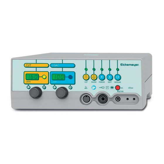
EN‐30 Instruction’s Manual MA510a_EN Frontal Panel 1 Level control for cut current 2 Level indication for cut current 3 Output indication for cut current 4 Level controls for coagulation current 5 Level indications for coagulation current 6 Output indications for coagulation current 7 Selection key and light for CUT function 8 Selection key and light for BLEND function 9 Selection key and light for FORCED COAG function 10 Selection key and light for SOFT COAG function 11 Selection key and light for BIPOLAR function 12 Alarm indicator for excessive impedance in the neutral electrode circuit 13 Handle connector for active electrode‐holder 14 Connector for neutral electrode connection 15 Foot‐switch connector ... -
Page 33: Operation Mode
EN‐31 EickTron 120 ‐ 160 MA510a_EN Operation Mode Switch On When switched on the electrosurgical unit performs automatically a test to establish the correct operation of itself and of the connected accessories as well. In case anomaly is found an alphanumeric message it is shown coded according to the chart codes brought in the chapter MAINTENANCE. This test lasts about 10 seconds. At the end of the control the equipment restores last use operational conditions. Neutral Electrode’s Circuit The neutral electrode is continually watched by a special circuit that prevents, danger of burns to the patient due the loss of contact between ... -
Page 34: Preselection Of The Deliverable Current
EN‐32 Instruction’s Manual MA510a_EN Preselection of the Deliverable Current The deliverable current for the surgical operations can have preselected : through push button for Cut Current (CUT) The best current for the cut is the pure sinusoidal wave without modulation that means with duty‐cycle 100%. Such current, proper for cut without coagulation. Coagulated‐Cut Current (BLEND) The coagulated‐cut current (BLEND) it is suited for coagulated cut when a deep coagulation together the cut is desired. This current is ... -
Page 35: Deep Coagulation Current (Soft Coag)
EN‐33 EickTron 120 ‐ 160 MA510a_EN Deep Coagulation Current (SOFT COAG) The low voltage and low modulation current (SOFT COAG) it is suited for coagulation of deep layers of the tissue in which the coagulation of the cellular albumin is gotten in absence of carbonization and without production of eschar. The process of coagulation is in this case more time expensive than that of the forced coagulation. Bipolar Coagulation Current (BIPOLAR) This current is low voltage pure sine current suited for coagulation without carbonization ... -
Page 36: Electrode (Oc)
EN‐34 Instruction’s Manual MA510a_EN Signaling of Excessive Impedance in the Circuit of Neutral Electrode (OC) For the meaning of this warning signal please refer to the previous description of the neutral electrode circuit. Adjustment of the Acoustic Signal Level To modify the emission acoustic signal it is necessary to follow those indications: Switch on the unit through the mains switch while the CUT pushbutton is maintained pressed ... -
Page 37: Connectors
EN‐35 EickTron 120 ‐ 160 MA510a_EN Connectors Neutral Electrode Connector This is the point of connection of the return plate or of the bipolar optional . adapter (REF 00498.04) for BIPOLAR function Handle Connector This is the point of connection of electrode handle. In the case of use of buckle indicated handle without finger switch it shall be connected to the “ACTIVE”. Foot‐switch Connector On the left part of the front panel it is foot‐switch connector. Instruction’s Manual Manuale d’Istruzioni PORTUGUES ... -
Page 38: Back Panel
EN‐36 Instruction’s Manual MA510a_EN Back Panel ® SURTRON (mod. 160) 1 Fuses holder/Voltage selector 2 Power On‐Off switch 3 Mains voltage connector 4 Equipotential connector Power Supply Module and Voltage Selector Power supply module is the connection point of mains voltage feeding to the unit. This module is provided with line fuses and the voltage selector. WARNING: before switch on the unit, operator has to verify that requested mains voltage corresponds to the voltage available from the electrical net. (see chapter INSTALLATION). Power On‐Off Switch The POWER ON/OFF mechanical switch is used to control power to the equipment. To power the equipment, press the switch in the direction of the 1. When the equipment is powered the front panel will illuminate. Pressing the switch in the 0 direction will cut power to the equipment, this ... -
Page 39: Technical Characteristics
EN‐37 EickTron 120 ‐ 160 MA510a_EN TECHNICAL CHARACTERISTICS EickTron Toll. Description 120 Electrosurgical unit code EKM10100.201A EKM10100.201A Minimum presectable power 0 ± 0% Level step 1 Digital level display Maximum output power CUT (W) ±20% 120 → 250Ω 160 → 250Ω Maximum output power BLEND (W) ± 20% 90 → 200Ω 120 → 200Ω Maximum output power COAG FORCED (W) ± 20% 80 → 150Ω 100 → 150Ω Maximum output power COAG SOFT (W) ± 20% 60 → 100Ω 80 → 100Ω Maximum output power BIPOLAR (W) ± 20% ... - Page 40 EN‐38 Instruction’s Manual MA510a_EN EickTron Toll. Description 120 EN55011 (CISPR 11) Class (Group/Class) 2 / B 2 / B Patient circuit ‐F‐ ‐F‐ Duty Cycle (action / pause) in seconds On 10 / Off 30 On 10 /Off 30 Output power control by foot‐switch or finger‐switch Defibrillation‐proof Equipotential binding ABS cabinet = PRESENT = NOT PRESENT ...
-
Page 41: Maintenance
EN‐39 EickTron 120 ‐ 160 MA510a_EN MAINTENANCE General No user adjustable parts are within the equipment, either for calibration or service purposes. The equipment housing must not be opened: the warranty is invalidated by any unauthorized entry into the unit. In the event any repair or adjustment work being necessary, the whole equipment should be returned to an Authorized Centre, together with a description of the fault. ... -
Page 42: Guide To The Solution Of The Problems
EN‐40 Instruction’s Manual MA510a_EN Guide to the Solution of the Problems In case of problems before all it is advised to check for the correct installation of the unit and for the correct connection of the accessories Problems Probable Cause Solution The equipment Interruption or absence of Verify the connection of the doesn't switch on. the main feeding. main cable. Verify ... -
Page 43: Repairs
EN‐41 EickTron 120 ‐ 160 MA510a_EN Repairs High frequency cables and electrode holder handle cannot be repaired. . Always substitute a damaged part with a new one Fuses Substitution Before substituting the fuse, disconnect the unit from the mains system Only use fuse of the kind 5x20; they must have those characteristics: T3.15A (slow) (230Vac mains voltage), T6.3A (115Vac mains voltage), proceed as follows: ... - Page 44 EN‐42 Instruction’s Manual MA510a_EN Check, by disconnecting the reference electrode cable, the functioning of the OC light. Active unit and check OC light and sound alarm warning. Check, by activating the CUT and COAG power switch, the functioning of the emission lights and sounds warnings ...
-
Page 45: Function And Safety Check And Test
EN‐43 EickTron 120 ‐ 160 MA510a_EN Function and Safety Check and Test At least once a year, the biomedical engineering department or other : qualified personnel should do the following check and test Check of the connectors and mains supply cord conditions. Visual check of the mechanical protections. Check of the protections against the danger due to liquid's pouring, dripping, moisture, liquid's penetration, cleanliness, sterilization and disinfection. Check of the Equipment's Data on the Label. Check of the availability of the Instruction's Manual. Check the functioning of the H.F. output controls. Check the uniformity of the resistance through the surface of the patient plate. ... -
Page 46: Diagrams
EN‐44 Instruction’s Manual MA510a_EN DIAGRAMS EICKTRON 120 Diagrams of half and maximum Diagrams of half and maximum Diagrams of half and maximum output power versus impedance output power versus impedance output power versus impedance ... - Page 47 EN‐45 EickTron 120 ‐ 160 MA510a_EN EICKTRON 120 Diagrams of BIPOLAR Diagrams of FORCED maximum Diagrams of SOFT maximum maximum mains voltage output mains voltage output versus Vp mains voltage output versus Vp versus Vp Instruction’s Manual Manuale d’Istruzioni PORTUGUES FRANCOIS ESPANOL ENGLISH ...
- Page 48 EN‐46 Instruction’s Manual MA510a_EN EICKTRON 160 Diagrams of half and maximum Diagrams of half and maximum Diagrams of half and maximum output power versus impedance output power versus impedance output power versus impedance ...
- Page 49 EN‐47 EickTron 120 ‐ 160 MA510a_EN EICKTRON 160 Diagrams of FORCED maximum Diagrams of SOFT maximum Diagrams of BIPOLAR mains voltage output versus Vp mains voltage output versus Vp maximum mains voltage output versus Vp LED SpA Via Selciatella 40 I-04011 Aprilia (LT) Italia ...
- Page 50 EN‐48 Instruction’s Manual MA510a_EN Information about elimination of this product (Applicable in the European Union and other European countries with separate collection systems) . On the end of the life, the present product mustn’t be eliminated as urban refusal, but it must be eliminated in a separated collection. If the product is eliminated in unsuitable way, it is possible that some parts of the product (for example some accumulators) could be negative for the environment and for the human health. ...
- Page 51 ...
Need help?
Do you have a question about the EICKTRON 120 and is the answer not in the manual?
Questions and answers