ALLEN & HEATH ML4000 Service Manual
Dual function live sound console
Hide thumbs
Also See for ML4000:
- User manual (56 pages) ,
- Quick start sheet (2 pages) ,
- User manual (4 pages)
Table of Contents
Advertisement
Advertisement
Table of Contents

Subscribe to Our Youtube Channel
Related Manuals for ALLEN & HEATH ML4000


Summary of Contents for ALLEN & HEATH ML4000
- Page 1 Dual Function Live Sound Console SERVICE MANUAL Publication AP4316...
- Page 2 Introduction This service manual provides technical information on the Allen & Heath ML4000 audio console. Included is the technical specification, system block diagram, circuit schematics with board layouts, and a spare parts list. Information on the power supply is available in a separate publication. Only technically qualified service personnel should carry out service work on the console and its power supply.
-
Page 3: Table Of Contents
BLOCK DIAGRAM..........M1 Mains Plug Wiring Instructions......5 INTERNAL ASSEMBLY MAP ...... M2-M3 General Precautions ..........5 MONO INPUT ..........D1-D4 ML4000 Key Features ......... 6 STEREO INPUT ........... D5-D8 Front Panel Layout ..........7 MASTER CONNECTOR......D9-D10 Rear Panel Layouts..........8 GROUP 1,3,5,7 ........ -
Page 4: Important Safety Instructions
Refer servicing to qualified technical personnel only. Installation Install the console in accordance with the instructions printed in this User Guide. Do not connect the output of power amplifiers directly to the console. Use audio connectors and plugs only for their intended purpose. ML4000 Service Manual... -
Page 5: Mains Plug Wiring Instructions
The console should be transported in the original packing or purpose built foam lined flightcase. Protect the control surface from damage during transit. The console is a large and heavy item. To avoid injury ensure adequate man power and precaution when lifting or moving the console. ML4000 Service Manual... -
Page 6: Ml4000 Key Features
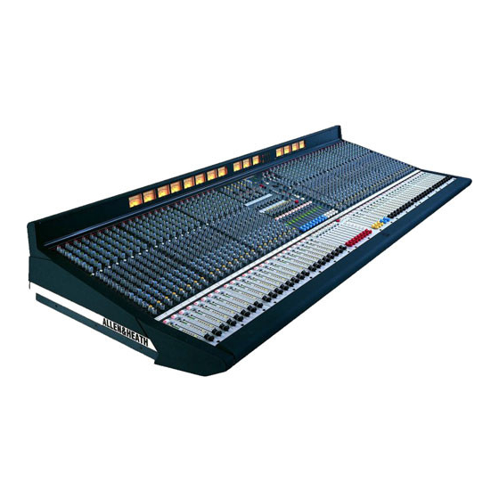
ML4000 Key Features The Allen & Heath ML4000 is a large format VCA equipped dual function live sound console providing many of the features of its larger brother the ML5000. It can be quickly configured for front-of-house (FOH) or stage monitor mixing. As one console suitable for both applications it is equally well suited to installation, rental and touring. -
Page 7: Front Panel Layout
SAFE SAFE SAFE SAFE SAFE SAFE/EDIT SAFE/EDIT SAFE/EDIT SAFE/EDIT SAFE/EDIT SELECT USING GROUP MUTE ASSIGN USING CH MUTES WEDGE PAFL PAFL PAFL PAFL PAFL PAFL PAFL PAFL PAFL PAFL PAFL PAFL mode MONITOR MUTE GROUP GROUP GROUP ML4000 Service Manual... -
Page 8: Rear Panel Layouts
INSERT SEND SEND SEND SEND SEND SEND SEND SEND SEND RETURN INTERCOM ALLEN & HEATH Made in England by A Division of Harman International Industries Limited Expander Sidecar Audio, link to main console, power and logic connectors. ML4000 Service Manual... -
Page 9: Technical Specifications
2-Track ......TRS jack ..ground comp, tip+ ..<50 ohm....0dBu ........Max +21dBu Local Monitor ....TRS jack ..ground comp, tip+ ..<50 ohm....0dBu ........Max +21dBu Headphones....TRS jack ..tip left, ring right..for stereo headphones >30 ohms ML4000 Service Manual... -
Page 10: System Block Diagram
9-10 LEV 11-12 LEV OSC/NOISE/TALKBACK INTERCOM TRIM OSC/NOISE TO TB SIDETONE LISTEN TALK TO INTERCOM PINK NOISE TRIM +48V TO PHONES TRIM TALK TO TB LAMP INTERCOM IN/OUT TB MIC 1kHz OSC CALL MONITOR DIM MONITOR DIM Disable ML4000 Service Manual... - Page 11 L AFL METERS 9-12 R AFL MIX MATRIX R AFL C METERS METER SELECT MONITOR SOURCE FROM INTERCOM PHONES WEDGE MON HEADPHONES TRIM TB DIM 2TRK MONO 2TRK LOCAL LOCAL MONITOR INPUT PAFL OUTPUT AFL PAFL LOGIC ML4000 Service Manual...
-
Page 12: Installation Details
87 kg (191 lbs) 24 Channel sidecar 40 kg (88 lbs) MPS14 psu 2.5 kg (5 lbs) HEADPHONES SOCKET LAMP SOCKETS UNDER ARMREST ML4000-24 = 1196 ML4000-24SC = 831 ML4000-32 = 1451 ML4000-40 = 1706 ML4000-48 = 1961 482.6 FC 76.2... -
Page 13: Earthing
0V earth at the console. Use good quality cables and connectors and check for correct wiring and reliable solder joints. Allow sufficient cable loop to prevent damage through stretching. ML4000 Service Manual... -
Page 14: Audio Connector Types And Wiring
Audio Connector Types and Wiring ML4000 Service Manual... -
Page 15: Gain Structure
The output faders are best operated around ‘-10’ to ‘0’ Using the Meters. The ML4000 provides metering for loudest average volume required. This allows at all important stages through the signal chain. For plenty of additional headroom if you need it. -
Page 16: Midi
MIDI MIDI Overview The ML4000 includes a Musical Instrument Digital Interface (MIDI) port. Standard 5-pin IN, THRU and MIDI OUT sockets allow connection to external MIDI RS232 equipment such as computer show control systems, DUMP sequencers, instruments data archiving devices. Applications include sophisticated ‘hands- EDIT SAFES off’... - Page 17 F0 00 01 1E 7F 7F 20 tx_event F7 CH 23 4E CH 47 These messages are subject to further development CH 24 4F CH 48 and addition. Please check the Allen & Heath Web site for the latest information. ML4000 Service Manual...
- Page 18 Transmit and Receive. The format for a single at a later date, for example a re-run of a previous packet is as follows: performance. You can also use the dump facility to program additional ML4000 consoles, for example <SysEx header> <packet type>...
-
Page 19: Console Computer And Operating Software
Important Note: If a sidecar expander is used with the ML4000 make sure it is running the same version of software as the master console. If it is necessary to replace the CPU assembly make sure the jumper links are correctly set on the replacement assembly. -
Page 20: Internal Option Links
Internal Options Links The ML4000 is designed to offer the utmost flexibility to satisfy the application without modification. However, the following internal link options are provided to allow customisation to satisfy the more specialist applications or personal preferences. Remember to set these internal links according to... -
Page 21: The Range
002-617 2.8 metre 37way Audio cable - To link sidecar to console AL4155 2.8 meter 9way Logic cable - To link sidecar to console AP4314 ML4000 Console User Guide AP4373 ML4000 Sidecar User Guide AP4316 ML4000 Console Service Manual AP3898... -
Page 22: Technical Drawings
It is recommended that the spares kit order code 002-699 is held and maintained by the service agent to enable in-field service repairs to the ML4000 independent of the ALLEN & HEATH factory. Commonly available items such as resistors, capacitors, tools and soldering equipment are not included. - Page 23 XLR 3 Pin Female Vertical PCB Mount AL2410 XLR 3 Pin Male Vertical PCB Mount AL2411 Switch Slide MINI SPDT PCB AL3081 Jack Socket ¼” Stereo Unswitched AL3407 Jack Socket ¼” Stereo Switched AL3410 Switch 2PCO Latching 90 Deg AL8065 ML4000 Service Manual...
- Page 24 Preset 10K Carbon Vertical Mini AC0250 Preset 22K Carbon Horizontal Adjust AC3980 Meter bulb 8V AD0013 VU Meter + 8V Bulb AD3321 Flex Cable 12 Way 90mm AH2228 Flex Cable 15 Way 90mm AH4091 Battery 2.4V 70mAh NI-MH AP3334 ML4000 Service Manual...
- Page 25 Zener Diode BZX79C 12V 250mW AE0232 IC Regulator 7818 AE3155 Diode BYW81P-200 15A AE3468 Diode BYV27-400 2A AE3469 Diode BYV26E 1A 1000V AE3470 Diode P6KE200A AE3471 Transistor Mosfet STP4NB80FP AE3472 IC SMPS UC3842AN AE3473 Bridge Rectifier 2KBP06M AE3477 ML4000 Service Manual...
- Page 26 Switch 2PCO Latching Vertical AL8057 Inductor 4.7uH 600mA AM3467 Inductor Ferrite Sleeve AM3657 Inductor 5MH 5A CMC AM3900 Inductor 330UH 1A AM3901 Inductor 150UH AM3902 Inductor 10UH AM3903 Inductor 1MH AM3904 Transformer HF Pulse PCB AM4006 Fan 80x80x25.5 12V AM4474 ML4000 Service Manual...
- Page 27 Technical Drawings The following section includes the full set of technical drawings associated with the ML4000. The BLOCK DIAGRAM is the same as printed in the User Guide and illustrates the signal flow through the console. The MAP DRAWINGS show the interconnection between the various circuit assemblies.
Need help?
Do you have a question about the ML4000 and is the answer not in the manual?
Questions and answers