ALLEN & HEATH ML4000 User Manual
Dual function live sound console
Hide thumbs
Also See for ML4000:
- Service manual (91 pages) ,
- User manual (56 pages) ,
- Quick start sheet (2 pages)
Table of Contents
Advertisement
Quick Links
Advertisement
Table of Contents

Subscribe to Our Youtube Channel
Related Manuals for ALLEN & HEATH ML4000


Summary of Contents for ALLEN & HEATH ML4000
- Page 1 Dual Function Live Sound Console USER GUIDE Publication AP4314...
-
Page 2: Introduction
Introduction This user guide presents a quick reference to the ML4000. We recommend that you read this fully before starting. Included is information on installing, connecting and operating the console, panel drawings, system block diagram and technical specification. For further information on the basic principles of audio system engineering, please refer to one of the specialist publications available from bookshops and audio equipment dealers. -
Page 3: Table Of Contents
Using the Engineers Wedge Monitor ....35 Mains Plug Wiring Instructions ......6 Matrix ..............36 General Precautions ..........6 2-Track Output........... 37 ML4000 Key Features ......... 7 VCA Groups............38 Quick Start Sheet..........8 VCA Groups Explained........38 System Block Diagram ........10 Assigning VCA Groups........ -
Page 4: Warranty
EMC and safety issues can contact Allen & Heath. NOTE: Any changes or modifications to the console not approved by Allen & Heath could void the compliance of the console and therefore the users authority to operate it. ML4000 User Guide... -
Page 5: Important Safety Instructions
Refer servicing to qualified technical personnel only. Installation Install the console in accordance with the instructions printed in this User Guide. Do not connect the output of power amplifiers directly to the console. Use audio connectors and plugs only for their intended purpose. ML4000 User Guide... -
Page 6: Mains Plug Wiring Instructions
The console should be transported in the original packing or purpose built foam lined flightcase. Protect the control surface from damage during transit. The console is a large and heavy item. To avoid injury ensure adequate man power and precaution when lifting or moving the console. ML4000 User Guide... -
Page 7: Ml4000 Key Features
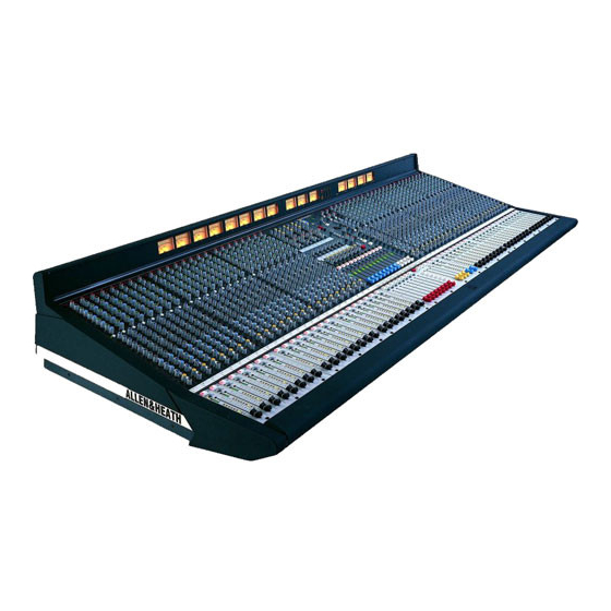
ML4000 Key Features The Allen & Heath ML4000 is a large format VCA equipped dual function live sound console providing many of the features of its larger brother the ML5000. It can be quickly configured for front-of-house (FOH) or stage monitor mixing. As one console suitable for both applications it is equally well suited to installation, rental and touring. -
Page 8: Quick Start Sheet
STEREO+ FILL PAN and BLEND = Two MONO PA controls adjust the balance between L, R and C. MAIN MIX = Routes the BLEND BLEND channel to the main L,R,C outputs. MAIN BLEND STEREO PA BLEND BLEND ML4000 User Guide... - Page 9 MIDI. PAFL 20 10 20 10 20 10 The channel does not respond to MIDI. CALL Check that it has not been made safe (green SAFE/EDIT LED on in normal console mode). PAFL CALL AFL-L AFL-R AFL-M ML4000 User Guide...
-
Page 10: System Block Diagram
11-12 LEV OSC/NOISE/TALKBACK INTERCOM TRIM OSC/NOISE TO TB SIDETONE LISTEN TALK TO INTERCOM PINK NOISE + 48V TRIM TO PHONES TRIM TALK TO TB LAMP INTERCOM IN/OUT TB MIC 1kHz OSC CALL MONITOR DIM MONITOR DIM Disable ML4000 User Guide... - Page 11 L AFL METERS 9-12 R AFL MIX R AFL MATRIX C METERS METER SELECT MONITOR SOURCE FROM INTERCOM PHONES WEDGE MON HEADPHONES TRIM TB DIM 2TRK MONO 2TRK LOCAL LOCAL MONITOR INPUT PAFL OUTPUT AFL PAFL LOGIC ML4000 User Guide...
-
Page 12: Technical Specifications
2-Track......TRS jack ..ground comp, tip+ ..<50 ohm....0dBu ........Max +21dBu Local Monitor ....TRS jack ..ground comp, tip+ ..<50 ohm....0dBu ........Max +21dBu Headphones....TRS jack ..tip left, ring right..for stereo headphones >30 ohms ML4000 User Guide... -
Page 13: The Range
The Range • • ML4000-32 32 mono, 4 stereo inputs 002-584 0.5 metre DC combiner lead • • ML4000-40 40 mono, 4 stereo inputs AP4314 ML4000 Console User Guide • • ML4000-48 48 mono, 4 stereo inputs AP4373 ML4000 Sidecar User Guide •... -
Page 14: Connecting The Power Supply
Connecting the Power Supply The ML4000 console range is supplied with the DO NO T O BSTRUCT VENTILATIO N O PENINGS. CAUTION MPS14 power supply unit. A second MPS14 may DO NO T O PEN. NO USER SERVICEABLE PARTS INSIDE. -
Page 15: Earthing
Use good quality cables and connectors and check for correct wiring and reliable solder joints. Allow sufficient cable loop to prevent damage through stretching. If you are not sure ... Contact your service or local Allen & Heath agent for advice. ML4000 User Guide... -
Page 16: Rear Panel Connections
P/AFL system. They are balanced and between equipment. operate at –2dBu. Up to two sidecars may be connected. WARNING Use only the DC power cable provided with the console. ML4000 User Guide... - Page 17 +23dBu maximum and are suited to driving line level equipment operating at nominal 0dBu or +4dBu. Note: The GRP and AUX output XLRs always remain on their respective connectors regardless of the setting of the front panel REVERSE switches. ML4000 User Guide...
-
Page 18: Audio Connector Types And Wiring
Audio Connector Types and Wiring ML4000 User Guide... -
Page 19: Gain Structure
The output faders are best operated around ‘-10’ to ‘0’ Using the Meters. The ML4000 provides metering for loudest average volume required. This allows at all important stages through the signal chain. For plenty of additional headroom if you need it. -
Page 20: Control Layout And Description
EDIT MUTE & VCA GRPS SAFE/EDIT SAFE/EDIT SAFE/EDIT SAFE/EDIT SAFE/EDIT SELECT USING GROUP MUTE ASSIGN USING CH MUTES WEDGE PAFL PAFL PAFL PAFL PAFL PAFL PAFL PAFL PAFL PAFL PAFL PAFL mode MONITOR MUTE GROUP GROUP GROUP ML4000 User Guide... -
Page 21: System Description
9-12 outputs or matrix 1-4 rotary masters for aux sends 1-8. They can be levels according to the setting of the meter select reversed with the group fader masters together with switch. the inserts for full featured monitor mixing. ML4000 User Guide... -
Page 22: Mono Input And Eq
150Hz), reduce handling noise and stage rumble, or protect the speakers from very low frequency energy (set around 30 to 50Hz). Switch out to preserve full sub energy for low frequency 1kHz sounds such as kick drum, bass and special effects. ML4000 User Guide... -
Page 23: Using The Equaliser
Use the in/out switch to compare the original and equalised sound. The equaliser has a flat response 1kHz and therefore no effect when all the cut/boost controls are set to their centre detented position. ML4000 User Guide... -
Page 24: Channel Group / Auxiliary Sends
9-10 and 11-12 are switched in pairs. In the up position the source is post-fade. When pressed the source is pre-fade. The pre-fade source follows the setting of the internal jumper links. STEREO 11-12 ML4000 User Guide... -
Page 25: Channel Internal Link Options
PRE-FADE SOURCE LEFT PRE-EQ L Special Sends. The aux sends can be used for POST-MUTE any application where an independent mix is PRE-FADE MUTE PRE-MUTE required. Select pre or post-fade and mono or stereo as required. CONNECTORS ML4000 User Guide... -
Page 26: Channel Main Mix And Fader
The switch also functions as an edit key when in EDIT GROUPS, EDIT SAFES or MIDI CHANNEL SELECT mode. The channel mute status is always GROUP displayed on the switch regardless of mode. ML4000 User Guide... -
Page 27: Removing The Fader
VU and LED bar meters to warn of potential overload. PK can flash, for providing finer resolution and dynamic display. example, if the preamp is clipping while signal reads low due to attenuation through an inserted processor. ML4000 User Guide... -
Page 28: Using Lcrplus
Using LCRplus STEREO + CENTRE FILL. A centre fill speaker is The ML4000 LCRplus system extends signal used to reinforce the sound to the first few rows of imaging beyond conventional LR and LCR panning the audience when the L and R speakers are by allowing full 3 speaker balance and positioning positioned far apart. - Page 29 BLEND volume associated with switched routing. While you could use the matrix to balance groups of sounds between the speakers, LCRplus lets you balance the image independently for each sound. ML4000 User Guide...
-
Page 30: Stereo Input And Eq
The low frequency band has a shelving + 10 response that cuts or boosts the lower (bass) frequencies by up to 15dB. The shelf turning point is 60Hz. E5 EQ IN. Switches the equaliser in or out. 1kHz ML4000 User Guide... -
Page 31: Using The Dual Inputs
You can also mono a stereo source by pressing both MONO L and MONO R together. Use this when the stereo image is too wide or not appropriate for the application. ML4000 User Guide... -
Page 32: Group / Aux Fader And Rotary Masters
It does not affect the C output. At the detented centre position the signal routes equally to L and R. PAN and BLEND combine to adjust the balance between the 3 outputs. The control has a 3dB attenuation at centre position. ML4000 User Guide... - Page 33 A 60mm smooth travel fader is PFL/AFL Monitoring fitted providing +10dB gain above the nominal 0dB The ML4000 intelligent P/AFL system provides the operating position. These faders control the output following operating capabilities: level of group/aux 1-12. They are not part of the console VCA group system.
-
Page 34: Configuring Groups And Auxes
Group output XLR connectors do not reverse. The matrix and sub grouping is always fed from the group signal regardless of mode. AUX MIX AUX OUT mode MONITOR INSERT GROUP MIX GROUP OUT MUTE EDIT/SAFE MAIN BLEND SUBGROUP MATRIX GROUP ML4000 User Guide... -
Page 35: Main Mix Masters
Pressing the TALK TO TB switch automatically dims the output by 20dB to prevent feedback between the local speaker and talkback mic. ML4000 User Guide... -
Page 36: Matrix
Press two related AFL switches together to listen to a related pair in stereo, ideal when checking stereo sends. The odd number master is fed to the left channel, even to right. ML4000 User Guide... -
Page 37: 2-Track Output
AFL. Press the related pair together to listen in stereo if you are using two matrix outputs as a stereo feed. Use TB to route talkback or the oscillator/noise generator to the matrix to test speakers and feeds. ML4000 User Guide... -
Page 38: Vca Groups
The ML4000 has 8 VCA groups. Mono and stereo to feed different groups of signals into the matrix. input channels can be assigned to one or more However, fewer such groups are usually required groups. - Page 39 C mixed CHANNEL PRE-FADE SENDS into the L and R so that you can listen to the LCR POST-FADE SENDS mix in stereo. MAIN MIX VCA GROUP CHANNEL MASTER FADER FADER DC VOLTAGE ML4000 User Guide...
-
Page 40: Assigning Vca Groups
CHANNEL GROUP 1 GROUP 2 GROUP 3 + 20 + 15 + 10 Example 3 CHANNEL GROUP 1 GROUP 2 GROUP 3 + 20 + 10 + 10 + 10 + 15 + 10 + 10dB (max) ML4000 User Guide... -
Page 41: Mute Groups
The assignment is edited or viewed one group at a time. The ML4000 has 8 mute groups. You can select more than one group at the same time. VCA group mutes cannot be assigned to the mute groups. -
Page 42: Snapshot Memories
Refer also to the section on MIDI /RS232 for details Recalling a snapshot does not turn off any mutes on archiving the console settings and memory which have been turned on by the Mute and VCA contents. groups. The groups always take priority. ML4000 User Guide... -
Page 43: Headphones / Local Monitor / Pafl
All monitor outputs automatically dim by 20dB when the TALK switch is pressed. The ML4000 features an intelligent P/AFL system that provides extended monitoring capability. The MONO inputs can be selected as mono PFL or stereo in- place AFL, the outputs as mono or stereo AFL. - Page 44 CLEAR ALL. Press this switch to turn off all currently selected PAFL and AFL switches. Its LED lights to show that one or more switches are active and can be cleared. ML4000 User Guide...
-
Page 45: Oscillator / Noise Generator
When you have finished using the generator be sure to disable it if you want to avoid the possibility of accidental operation during performance. ML4000 User Guide... -
Page 46: Intercom
LISTEN is turned off. The controls are logically grouped near the talkback section for easy single handed operation of the listen, signal and talk functions. ML4000 User Guide... -
Page 47: Talkback
TB enable switches and use TALK TO TB as a monitor dim function, for example when using the intercom, when talking with someone at the console, or to dim the pink noise signal when testing speakers. ML4000 User Guide... -
Page 48: Meterpod
AUX 9-12 MTX 1-4 The Console Meterpod The ML4000 continues the Allen & Heath tradition to provide full signal metering at all key stages in the signal chain. The channel LED meters give you important signal information and multipoint peak PAFL sensing. -
Page 49: Meter Types
Both VU and LED bar types of meter are provided mix 1 to 8. Depending on the setting of the master on the ML4000. This gives you the best of both section mode switches these display group or aux average and peak metering. -
Page 50: Midi Overview
MIDI MIDI Overview The ML4000 includes a Musical Instrument Digital Interface (MIDI) port. Standard 5-pin IN, THRU and MIDI OUT sockets allow connection to external MIDI RS232 equipment such as computer show control systems, DUMP sequencers, instruments data archiving devices. Applications include sophisticated ‘hands- EDIT SAFES off’... -
Page 51: Midi Channel Mutes
CH 24 4F CH 48 dbx Drive Rack F0 00 01 1E 7F 7F 20 tx_event F7 These messages are subject to further development and addition. Please check the Allen & Heath Web site for the latest information. ML4000 User Guide... -
Page 52: Archiving The Console Settings
Transmit and Receive. The format for a single at a later date, for example a re-run of a previous packet is as follows: performance. You can also use the dump facility to program additional ML4000 consoles, for example <SysEx header> <packet type>... -
Page 53: Operating System Technical Support
You can check the current version number of the The console settings are saved when power is ML4000 software running on the console using a removed. On power up these settings are restored. PC connected via RS232. Instructions for this are provided on the Allen &... -
Page 54: Blank For User Notes
USER NOTES : ML4000 User Guide... -
Page 55: Cue Sheet
EDIT MUTE & VCA GRPS SAFE/EDIT SAFE/EDIT SAFE/EDIT SAFE/EDIT SAFE/EDIT SELECT USING GROUP MUTE ASSIGN USING CH MUTES WEDGE PAFL PAFL PAFL PAFL PAFL PAFL PAFL PAFL PAFL PAFL PAFL PAFL mode MONITOR MUTE GROUP GROUP GROUP ML4000 User Guide... - Page 56 Visit Allen & Heath : http://www.allen-heath.com http://www.mlseries.com ML4000 User Guide ML4000 User Guide...
Need help?
Do you have a question about the ML4000 and is the answer not in the manual?
Questions and answers