Table of Contents

Related Manuals for Toro Groundsmaster 360 31200 Series


Summary of Contents for Toro Groundsmaster 360 31200 Series
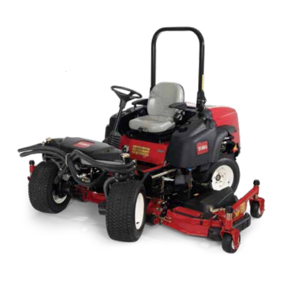
- Page 1 Form No. 3384-955 Rev B Groundsmaster ® 360 4-Wheel Drive Multi-Purpose Machine Model No. 31200—Serial No. 314000001 and Up Model No. 31200A—Serial No. 314000001 and Up *3384-955* B Register at www.Toro.com. Original Instructions (EN)
- Page 2 Whenever you need service, genuine Toro parts, or additional information, contact an Authorized Service Dealer or Toro Customer Service and have the model and serial numbers of your product ready. Figure 1 identifies the location of the model and serial numbers ©...
-
Page 3: Table Of Contents
Safety ............... 4 Cooling System Maintenance ......50 Safe Operating Practices........4 Checking the Cooling System ......50 Toro Riding Mower Safety........6 Cleaning the Radiator ........50 Safety and Instructional Decals ......7 Brake Maintenance ..........51 Setup ..............12 Adjusting the Service Brakes ...... -
Page 4: Safety
Preparation Safety • While mowing, always wear substantial footwear and long trousers. Do not operate the equipment These machines meet or exceed CEN standard EN when barefoot or wearing open sandals. ISO 5395:2013 and ANSI B71.4-2012 specifications in effect at the time of production. •... - Page 5 Rollover Protection System • Mow only in daylight or in good artificial light. (ROPS) - Use and Maintenance • Before attempting to start the engine, disengage all blade attachment clutches and shift into neutral. • The ROPS is an integral and effective safety •...
-
Page 6: Toro Riding Mower Safety
The following list contains safety information specific downhill. Weight transfer to the front wheels to Toro products or other safety information that you may cause drive wheels to slip and cause loss of must know that is not included in the CEN standard. -
Page 7: Safety And Instructional Decals
Safety and Instructional Decals Safety decals and instructions are easily visible to the operator and are located near any area of potential danger. Replace any decal that is damaged or lost. decal93-6696 93–6696 1. Stored energy hazard—read the Operator's Manual. decal117-3270 117-3270 1. - Page 8 decal106-2353 106-2353 1. Electrical power point decal117-4766 117-4766 decal120-6604 1. Cutting/dismemberment hazard; fan—stay away from 120-6604 moving parts, keep all guards and shields in place. 1. Thrown object hazard—keep bystanders away from the machine. 2. Cutting/dismemberment hazard of hand, mower blade—stay away from moving parts, keep all guards and shields in place.
- Page 9 decal117-2718 117–2718 decal115-0492 115-0492 1. Height of cut (mm) decal117-3273 117-3273 1. Warning—read the Operator's Manual. 6. Thrown object hazard—keep bystanders a safe distance from the machine. 2. Warning—do not operate this machine unless you are trained. 7. Warning—lock the parking brake, stop the engine and remove the ignition key before leaving the machine.
- Page 10 decal107-2916 107-2916 1. Remove the ignition key and read the 2. Thrown object hazard—do not operate 3. Cutting/dismemberment hazard of Operator's Manual before servicing or the mower with the deflector up or hand or foot, mower blade—stay away performing maintenance. removed, keep the deflector in place;...
- Page 11 decalbatterysymbols Battery Symbols Some or all of these symbols are on your battery 1. Explosion hazard 6. Keep bystanders a safe distance from the battery. 7. Wear eye protection; 2. No fire, open flame, or smoking. explosive gases can cause blindness and other injuries 3.
-
Page 12: Setup
Setup Loose Parts Use the chart below to verify that all parts have been shipped. Procedure Description Qty. – No parts required Adjust the ROPS – No parts required Check the tire pressure. Check the hydraulic fluid, engine oil, – No parts required and coolant levels. -
Page 13: Checking The Fluid Levels
Product Overview Controls Checking the Tire Pressure Become familiar with all the controls before you start the engine and operate the machine. No Parts Required Traction Pedal Procedure The traction pedal (Figure 4) controls the forward and reverse operation. Press the top of the pedal to move The tires are over inflated for shipping. - Page 14 Parking Brake Ignition Switch To engage the parking brake, push down on the brake The ignition switch has three positions: Off, pedal and press the top forward to latch (Figure 4). To On/Preheat, and Start (Figure release the parking brake, press the brake pedal until the parking brake latch retracts.
- Page 15 Using the InfoCenter LCD Display InfoCenter Icon Description SERVICE DUE Indicates when scheduled service The InfoCenter LCD display shows information about should be performed your machine, such as the operating status, various diagnostics, and other information about the machine Engine rpm/status—indicates the engine rpm (Figure 7).
- Page 16 InfoCenter Icon Description (cont'd.) Faults The Faults menu contains a list of the recent machine faults. Refer to the Service Manual or your Authorized Toro Distributor for more InfoCenter information on the Faults menu and the information contained there. Bad or failed...
- Page 17 Wait until the red indicator light of the InfoCenter is either 0000 or 1234. illuminates. If you changed the PIN code and forgot the Note: code, contact your Authorized Toro Distributor for If the InfoCenter accepts the PIN code assistance. and the protected menu is unlocked, the word...
-
Page 18: Specifications
• Avoid prolonged breathing of vapors. Authorized Service Dealer or Distributor or go to • Keep face away from nozzle and fuel tank www.Toro.com for a list of all approved attachments or conditioner opening. and accessories. • Keep fuel away from eyes and skin. -
Page 19: Filling The Fuel Tank
• Painted surfaces may be damaged by biodiesel DANGER blends. In certain conditions during fueling, static • Monitor seals, hoses, gaskets in contact with fuel electricity can be released causing a spark as they may be degraded over time. which can ignite the fuel vapors. A fire or •... - Page 20 Monitor seals, hoses, gaskets in contact with fuel as they may be degraded over time. • Fuel filter plugging may be expected for a time after converting to biodiesel blends. • Contact your Authorized Toro Distributor if you wish for more information on biodiesel.
-
Page 21: Using The Rollover Protection System (Rops)
Using the Rollover Protection System (ROPS) • Keep the roll bar in the raised and locked position and use the seat belt when operating the machine. • Be certain that the seat belt can be released quickly in the event of an emergency. •... -
Page 22: Think Safety First
Think Safety First Starting and Stopping the Engine Please read all safety instructions and symbols in the safety section. Knowing this information could help you or bystanders avoid injury. Starting the Engine Raise the roll bar up and lock it into place, sit on DANGER the seat, and fasten the seat belt. -
Page 23: Driving The Machine
Cutting Grass with the off and check fluid levels, check for oil leaks, loose parts, and any other noticeable Machine malfunctions. Note: Cutting grass at a rate that loads the engine CAUTION promotes DPF regeneration. Shut the engine off and wait for all Move the machine to the job site. -
Page 24: Diesel Particulate Filter Regeneration
Diesel Particulate Filter Important: Minimize the amount of time that you idle the engine or operate the engine at low-engine Regeneration speed to help reduce the accumulation of soot in the soot filter. The diesel particulate filter (DPF) is part of the exhaust system. - Page 25 DPF Ash Accumulation • When enough ash accumulates, the engine computer sends information to the InfoCenter in • The lighter ash is discharged through the exhaust the form of a system advisory or an engine fault to system; the heavier ash collects in the soot filter. indicate the accumulation of ash in the DPF.
- Page 26 Types of Diesel Particulate Filter Regeneration Types of diesel particulate filter regeneration that are performed while the machine is operating: Type of Regeneration Conditions for DPF regeneration DPF description of operation Passive Occurs during normal operation of the machine at The InfoCenter does not display an icon indicating high-engine speed or high-engine load passive regeneration.
- Page 27 DPF is already in need of a parked When the recovery-regeneration icon regeneration displayed in the InfoCenter, a recovery regeneration is requested. Contact your Authorized Toro Distributor to have a service technician perform the recovery regeneration. • A recovery regeneration requires up to 4 hours to complete.
- Page 28 Reset Regeneration Parked Regeneration g214713 g214711 Figure 21 Figure 20 Parked-regeneration request icon Assist/reset-regeneration icon • The parked-regeneration requested icon displays • The assist/reset-regeneration icon displays in the in the InfoCenter (Figure 21). InfoCenter (Figure 20). • If a parked regeneration is needed, the InfoCenter •...
- Page 29 Engage the parking brake. Set the throttle to the low I position. Performing a Parked Regeneration Note: For instructions on unlocking protected menus, refer to Accessing Protected Menus (page 17). Access the protected menu and unlock the protected settings submenu (Figure 23);...
- Page 30 g211986 g212405 Figure 27 Figure 29 Move the throttle control to and press LOW IDLE The “Waiting on ” message displays the center button (Figure 28). (Figure 30). g212372 g212406 Figure 28 Figure 30 The following messages display as the parked The computer determines whether the regeneration process begins: regeneration runs.
- Page 31 The engine is cold—wait. The engine is warm—wait. The engine hot—regeneration in progress (percent complete). The parked regeneration is complete when the “Regen Complete” message displays in the InfoCenter. Press the left button to exit to the home screen (Figure 33).
-
Page 32: Steering Selection
You need a distributor technician to perform the Note: If the steering system is misaligned after recovery regeneration process; contact your Authorized Toro Distributor. repeated 2 wheel steering to 4 wheel steering engagements, refer to Correcting Steering Misalignment in the Maintenance Section. -
Page 33: The Safety Interlock System
Understanding the Safety Interlock Important: Do not continue to hold the switch back after the mower has fully raised. Doing so System will damage the hydraulic system. The safety interlock system is designed to prevent the Note: To lock the mower deck in a raised position, engine from starting unless: raise the deck past the 15 cm (6 inch) position, remove the height of cut stop pin, and place the pin in... -
Page 34: Positioning The Standard Seat
position. Try starting the engine; the engine should not crank. Positioning the Standard Seat Changing the Seat Position g004489 Figure 39 The seat can move forward and backward. Position the seat where you have the best control of the 1. Seat suspension knob 2. - Page 35 Changing the Weight Adjustment 0 = No curvature 1 = Maximum curvature at the top The seat can be adjusted to provide a smooth and comfortable ride. 2 = Maximum curvature at the bottom Important: To adjust the seat for the drivers weight the driver must be seated and the ignition Adjusting the Armrests key moved to the On position.
-
Page 36: Raising/Lowering The Seat
Raising/Lowering the Seat Pushing the Machine by Hand To access the hydraulic and other systems under the seat, you need to unlatch the seat and swing it If the machine stalls, runs out of fuel, etc. you may forward. need to push it. To do so, you first need to open both Move the seat latch, located on the left side of of the hydraulic by-pass valves. -
Page 37: Loading Machines
Loading Machines Use extreme caution when loading units on trailers or trucks. One full width ramp that is wide enough to extend beyond the rear tires is recommended instead of individual ramps for each side of the unit (Figure 44). The lower rear section of the tractor frame extends back between the rear wheels and serves as a stop for tipping backward. -
Page 38: Transporting Machines
g000951 Figure 44 1. Trailer 3. Not greater than 15 degrees 2. Full width ramp 4. Full width ramp—side view Transporting Machines WARNING Driving on the street or roadway without turn signals, lights, reflective markings, or a slow moving vehicle emblem is dangerous and can lead to accidents causing personal injury. -
Page 39: Operating Tips
Sharpen the blades as necessary. If a blade which enhances decomposition and fertilization. is damaged or worn, replace it immediately with a genuine Toro replacement blade. Refer to Servicing the Cutting Blades. Cutting Speed To improve cut quality, use a slower ground speed. -
Page 40: Maintenance
Service Manual is also available for purchase from your Authorized Toro Distributor. Note: Looking for an Electrical Schematic or Hydraulic Schematic for your machine? Download a free copy of the schematic by visiting www.Toro.com and searching for your machine from the Manuals link on the home page. -
Page 41: Daily Maintenance Checklist
Daily Maintenance Checklist Duplicate this page for routine use. Maintenance Check Item For the week of: Mon. Tues. Wed. Thurs. Fri. Sat. Sun. Check Safety Interlock Operation Check Parking Brake Operation Check Fuel Level Check Hydraulic Oil Level Check Engine Oil Level Check Cooling System Fluid Level Check Drain Water/Fuel... -
Page 42: Pre-Maintenance Procedures
decal131-1946 Figure 46 Service Interval Chart Pre-Maintenance Procedures Using the Hood Prop Rod Release the hood latches. Lift up on the hood until the prop rod can be positioned behind the frame tube (Figure 47). Lower the hood until the rod is in front of and resting against the frame tube. -
Page 43: Lubrication
Lubrication wear. Lubricate the grease fittings immediately after every washing, regardless of interval specified. Wipe the grease fittings clean so foreign matter Greasing the Bearings and cannot be forced into the bearing or bushing. Bushings Pump grease into the fittings. Wipe off excess grease. -
Page 44: Engine Maintenance
• Alternate oil: SAE 10W-30 or 5W-30 (all migrating into the intake when the filter is temperatures) removed. Toro Premium Engine Oil is available from your Remove and replace the filter (Figure 50). Authorized Toro Distributor in either 15W-40 or Cleaning of the used element is not 10W-30 viscosity grades. - Page 45 Checking the Engine-Oil Level Crankcase Oil Capacity Service Interval: Before each use or daily Approximately 5.2 liters (5.5 quarts) with the filter. The engine is shipped with oil in the crankcase; Changing the Engine Oil and Filter however, the oil level must be checked before and after the engine is first started.
-
Page 46: Servicing The Diesel-Oxidation Catalyst (Doc) And The Soot Filter
Refer to the Engine section in the Service Manual for information on disassembling and assembling the diesel-oxidation catalyst and the soot filter of the DPF. Refer to your Authorized Toro Distributor for g007367 diesel-oxidation catalyst and the soot filter Figure 55 replacement parts or service. -
Page 47: Servicing The Engine Fuel Filter
Checking the Fuel Lines Remove the filter canister and clean the mounting surface. and Connections Lubricate the gasket on the filter canister with clean oil. Check the fuel lines and connections every 400 hours or yearly, whichever comes first. Inspect them for Install the filter canister by hand until the gasket deterioration, damage, or loose connections. -
Page 48: Electrical System Maintenance
Electrical System bicarbonate of soda solution. Flush the top surface with water after cleaning it. Do not remove the fill caps Maintenance while cleaning the battery. The battery cables must be tight on the terminals to Important: Whenever working with the electrical provide good electrical contact. -
Page 49: Storing The Battery
Storing the Battery Drive System Maintenance If the machine will be stored more than 30 days, remove the battery and charge it fully. Either store it on a shelf or on the machine. Leave the cables disconnected if it is stored on the machine. Store Checking the Tire Pressure the battery in a cool atmosphere to avoid quick deterioration of the charge in the battery. -
Page 50: Cooling System Maintenance
Cooling System If coolant level is low, remove the expansion tank cap and replenish the system. Do not overfill. Maintenance Install the expansion tank cap. DANGER Discharge of hot pressurized coolant or touching hot radiator and surrounding parts can cause severe burns. •... -
Page 51: Brake Maintenance
Brake Maintenance Adjusting the Service Brakes Adjust the service brakes when there is more than 25 mm (1 inch) of free travel of the brake pedal, or when the brakes do not work effectively. Free travel is the distance the brake pedal moves before you feel braking resistance. -
Page 52: Adjusting The Parking Brake
Adjusting the Parking Belt Maintenance Brake Checking the Alternator If the parking brake fails to engage, an adjustment to the brake pawl is required. Belt Loosen the 2 screws securing the parking brake Service Interval: After the first 10 hours pawl to the frame (Figure 62). -
Page 53: Controls System Maintenance
Controls System Maintenance Adjusting the Traction Drive for Neutral Note: If the machine has recently had the hydraulic oil changed or the traction motors or hoses replaced, any air trapped in the system will have to be worked out prior to performing this procedure. This can be accomplished by operating the machine in forward and reverse for a few minutes and then replenishing the oil as required. -
Page 54: Adjusting The Mow Speed Limiter Lever
Adjusting the Mow Speed Loosen the jam nut on the stop bolt for the traction pedal (Figure 65). Limiter Lever The mow speed limiter lever (Figure 66) can be flipped forward to limit the traction speed while operating. Disengage the PTO, release the traction pedal to the neutral position and set the parking brake. -
Page 55: Hydraulic System Maintenance
Toro Premium Transmission/Hydraulic Tractor Fluid (Available in 5 gallon pails or 55 gallon drums. See parts catalog or Toro distributor for part numbers.) Alternate fluids: If the Toro fluid is not available, Mobil® 424 hydraulic fluid may be used. g014190... -
Page 56: Cleaning
Cleaning Waste Disposal Engine oil, batteries, hydraulic oil, and engine coolant are pollutants to the environment. Dispose of these according to your state and local regulations. g014393 Figure 68 1. Transmission case drain 3. Hydraulic reservoir drain plug plug 2. Filter Clean the area around the hydraulic oil filter and remove it (Figure... -
Page 57: Storage
Storage Coat the cable terminals and battery posts with Grafo 112X skin-over grease (Toro Part No. 505-47) or petroleum jelly to prevent Engine corrosion. Slowly recharge the battery for 24 hours Drain the engine oil from the oil pan and replace every 60 days to prevent lead sulfation of the drain plug. - Page 58 Notes:...
- Page 59 Notes:...
- Page 60 Countries Other than the United States or Canada Customers who have purchased Toro products exported from the United States or Canada should contact their Toro Distributor (Dealer) to obtain guarantee policies for your country, province, or state. If for any reason you are dissatisfied with your Distributor's service or have difficulty obtaining guarantee information, contact the Toro importer.
Need help?
Do you have a question about the Groundsmaster 360 31200 Series and is the answer not in the manual?
Questions and answers