Table of Contents
Advertisement
INSTALLATION
MANUAL
CONTENTS
GENERAL . . . . . . . . . . . . . . . . . . . . . . . . . . . . . . . . 5
SAFETY CONSIDERATIONS . . . . . . . . . . . . . . . . . 5
INSPECTION. . . . . . . . . . . . . . . . . . . . . . . . . . . . . . 5
REFERENCE. . . . . . . . . . . . . . . . . . . . . . . . . . . . . . 6
RENEWAL PARTS . . . . . . . . . . . . . . . . . . . . . . . . . 6
APPROVALS . . . . . . . . . . . . . . . . . . . . . . . . . . . . . 6
PRODUCT NOMENCLATURE . . . . . . . . . . . . . . . . 6
INSTALLATION . . . . . . . . . . . . . . . . . . . . . . . . . . . 8
OPERATION . . . . . . . . . . . . . . . . . . . . . . . . . . . . . 39
START-UP (COOLING) . . . . . . . . . . . . . . . . . . . . 45
START-UP (GAS HEAT). . . . . . . . . . . . . . . . . . . . 45
TROUBLESHOOTING . . . . . . . . . . . . . . . . . . . . . 48
SEE THE FOLLOWING PAGES FOR A COMPLETE TABLE OF CONTENTS.
NOTES, CAUTIONS AND WARNINGS
The installer should pay particular attention to the words:
NOTE, CAUTION, and WARNING. Notes are intended to
clarify or make the installation easier. Cautions are given to
prevent equipment damage. Warnings are given to alert
installer that personal injury and/or equipment damage may
result if installation procedure is not handled properly.
CAUTION:
READ ALL SAFETY GUIDES BEFORE YOU
BEGIN TO INSTALL YOUR UNIT.
SAVE THIS MANUAL
SUNLINE™
GAS/ELECTRIC SINGLE PACKAGE
AIR CONDITIONERS
D(CE, CG) 036, 048, 060 & 072
D(HE, HG) 036, 048 & 060
290699-YIM-B-0607
Advertisement
Table of Contents
Troubleshooting

Subscribe to Our Youtube Channel
Related Manuals for York SUNLINE DCG Series


Summary of Contents for York SUNLINE DCG Series
- Page 1 INSTALLATION SUNLINE™ MANUAL GAS/ELECTRIC SINGLE PACKAGE AIR CONDITIONERS CONTENTS D(CE, CG) 036, 048, 060 & 072 D(HE, HG) 036, 048 & 060 GENERAL ....... . 5 SAFETY CONSIDERATIONS .
-
Page 2: Table Of Contents
290699-YIM-B-0607 TABLE OF CONTENTS GENERAL........5 LOW-PRESSURE LIMIT SWITCH. - Page 3 290699-YIM-B-0607 LIST OF FIGURES Fig. # Pg. # Fig. # Pg. # RECOMMENDED DRAIN PIPING....10 UNIT DIMENSIONS (3 - 6 TON COOLING/GAS HEAT) FRONT VIEW . . 30 COMPRESSOR RESTRAINING BRACKET .
- Page 4 290699-YIM-B-0607 LIST OF TABLES Tbl. # Pg. # Tbl. # Pg. # UNIT APPLICATION DATA (D(CE, CG), D(HE, HG)) . 9 UTILITIES ENTRY ......32 CONTROL WIRE SIZES .
-
Page 5: General
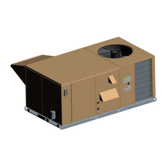
290699-YIM-B-0607 GENERAL YORK Model D(CE, CG) and D(HE, HG) units are either single package cooling units or single package FIRE OR EXPLOSION HAZARD gas-fired central heating furnaces with cooling unit. Both are designed for outdoor installation on a rooftop Failure to follow safety warnings exactly could or slab. -
Page 6: Reference
D(HE, HG) 036-060, 290699 codes including, but not limited to, building, electrical, and mechanical codes. RENEWAL PARTS ® Contact your local York parts distribution center for authorized replacement parts. APPROVALS Improper installation may create a condition where the operation of the product could cause Design listed by CSA as follows: personal injury or property damage. - Page 7 290699-YIM-B-0607 PRODUCT CATEGORY VOLTAGE CODE D = Single Package Air Conditioner 25 = 208/230-3-60 (Air Cooled) 46 = 460-3-60 58 = 575-3-60 PRODUCT GENERATION NOMINAL GAS HEATING 3 = 3rd Generation OUTPUT CAPACITY 8 = 8th Generation 9 = 9th Generation 040 = 40 MBH 060 = 60 MBH 079 = 79 MBH...
-
Page 8: Installation
290699-YIM-B-0607 INSTALLATION LIMITATIONS These units must be installed in accordance with the INSTALLATION SAFETY INFORMATION: following national and local safety codes: Read these instructions before continuing this appli- In U.S.A.: ance installation. This is an outdoor combination heat- ing and cooling unit. The installer must assure that •... -
Page 9: Location
LOCATION If a unit is to be installed on a roof curb or special frame other than a YORK roof curb, gasketing must be Use the following guidelines to select a suitable loca- applied to all surfaces that come in contact with the unit tion for these units. -
Page 10: Ductwork
290699-YIM-B-0607 Sections 7.2, 7.3 or 7.4 of Gas Installation Codes CSA- CONDENSATE DRAIN B149.1 (in Canada) and/or applicable provisions of the local building codes. Refer to Dimensions and Clear- Plumbing must conform to local codes. Use a sealing ances shown in Figures 10 through 13 and Tables 18 compound on male pipe threads. -
Page 11: Filters
290699-YIM-B-0607 • Electric Heat compartment • Gas Heat compartment Do not loosen compressor mounting bolts. • Blower compartment • Main control box FILTERS • Filter compartment One-inch or two-inch filters can be supplied with each unit. Filters must always be installed ahead of the Refer to the Dimensions and Clearances shown in Fig- evaporator coil and must be kept clean or replaced with ures 10, 11, 13 and 14 for location of these access... -
Page 12: Typical Field Power & Control Wiring 12
290699-YIM-B-0607 TYPICAL POWER WIRING REFER TO THE ELECTRICAL DATA TABLES TO SIZE THE DISCONNECT SWITCH, OVERCURRENT PROTEC- TION AND WIRING. TYPICAL CONTROL WIRING COOLING / HEATING (24 VOLT THERMOSTAT) COOLING O NLY ( 24 V OLT THERMOSTAT) THERMOSTAT TERMINALS THERMOSTAT UNIT TERMINAL UNIT TERMINAL TERMINALS... -
Page 13: Thermostat
290699-YIM-B-0607 THERMOSTAT The room thermostat should be located on an inside wall approximately 56 inches above the floor where it When connecting electrical power and control will not be subject to drafts, sun exposure or heat from wiring to the unit, waterproof type connectors electrical fixtures or appliances. -
Page 14: Gas Heat
290699-YIM-B-0607 TABLE 3: ELECTRIC HEATER CFM LIMITATIONS MINIMUM SUPPLY AIR CFM UNITMODEL SIZE NOMINAL VOLTAGE HEATER SIZE NOMINAL KW TONS 208/230-3-60 1100 1100 1200 1200 1300 460-3-60 1100 1200 1200 1300 575-3-60 1200 1200 1300 208/230-3-60 1300 1300 1300 1300 1300 460-3-60 1300... -
Page 15: Gas Piping
290699-YIM-B-0607 GAS PIPING Two grommets are shipped in the blower compartment (in parts bag taped to the blower housing) of every unit Proper sizing of gas piping depends on the cubic feet with gas heat and should be used in the knockouts per hour of gas flow required, specific gravity of the gas when the gas piping penetrates the front of the unit. -
Page 16: L.p. Units, Tanks And Piping
290699-YIM-B-0607 FIRE OR EXPLOSION HAZARD Failure to follow the safety warning exactly could result in serious injury, death or property damage. Never test for gas leaks with an open flame. use a commercially available soap solution made specifically for the detection of leaks to check all connections. -
Page 17: Vent And Combustion Air Hoods
290699-YIM-B-0607 L.P./propane gas is an excellent solvent and special pipe compound must be used when assembling piping for this gas as it will quickly dissolve white lead or most standard commercial compounds. Shellac base com- pounds such as Rectorseal #5 are satisfactory for this type of gas. -
Page 18: Economizer And Power Exhaust Damper Set Point Adjustments And Information
290699-YIM-B-0607 Power exhaust is only available as a field installed Adjusting screw (located on the damper control mod- accessory. ule) counterclockwise until the desired minimum damper position has been attained. ECONOMIZER AND POWER EXHAUST DAMPER SET POINT ADJUSTMENTS AND INFORMATION ENTHALPY SET POINT ADJUSTMENT The enthalpy set point may now be set by selecting the Remove the economizer access panel from the unit. - Page 19 290699-YIM-B-0607 CONTROL POINT CONTROL APPROX. CURVE (29) (32) (35) (38) (41) (43) AT 50% RH 73 (23) 70 (21) (27) 67 (19) 63 (17) (24) (21) (18) (16) (13) (10) (24) (27) (41) (43) (10) (13) (16) (18) (21) (29) (32) (35) (38)
-
Page 20: Center Of Gravity (All Models)
290699-YIM-B-0607 BACK OF UNIT BACK OF UNIT APPROXIMATE APPROXIMATE CENTER OF GRAVITY CENTER OF GRAVITY CONDENSER COIL CONDENSER COIL END OF UNIT END OF UNIT FRONT OF UNIT FRONT OF UNIT FIGURE 9 - FOUR AND SIX POINT LOADING TABLE 6: CENTER OF GRAVITY (ALL MODELS) DIMENSION 3 - 5 TON 6 TON... -
Page 21: D(Ce, Cg) Physical Data
290699-YIM-B-0607 TABLE 9: D(CE, CG) PHYSICAL DATA D(CE, CG) MODELS Centrifugal Blower (Dia. x Wd. in.) 12 X 10 12 X 10 12 X 10 12 X 11 EVAPORATOR Fan Motor HP (Direct Drive) BLOWER Fan Motor HP (Belt Drive) 1 1/2 1 1/2 1 1/2... - Page 22 290699-YIM-B-0607 TABLE 11: D(HE, HG) PHYSICAL DATA D(HE, HG) MODELS Centrifugal Blower (Dia. x Wd. in.) 12 X 10 12 X 10 12 X 10 EVAPORATOR BLOWER Fan Motor HP (Belt Drive) 1 1/2 1 1/2 1 1/2 Rows Deep EVAPORATOR Fins Per Inch COIL...
-
Page 23: Electrical Data - D(Ce, Cg) 036-072 Direct Drive
290699-YIM-B-0607 TABLE 13: ELECTRICAL DATA - D(CE, CG) 036-072 DIRECT DRIVE COMPRESSORS MIN. MAX. FUSE/ OD FAN MODEL BLOWER ELECTRIC HEATER HEATER HEATER CIRCUIT BRKR VOLTAGE MOTOR TONNAGE MOTOR MODEL NO. AMPS AMPACITY SIZE EACH EACH (AMPS) (AMPS) None 16.6 2CE04510525 11.1 19.4... - Page 24 290699-YIM-B-0607 TABLE 13: ELECTRICAL DATA - D(CE, CG) 036-072 DIRECT DRIVE (CONT.) COMPRESSORS MIN. MAX. FUSE/ OD FAN MODEL BLOWER ELECTRIC HEATER HEATER HEATER CIRCUIT BRKR VOLTAGE MOTOR TONNAGE MOTOR MODEL NO. AMPS AMPACITY SIZE EACH EACH (AMPS) (AMPS) None 27.9 2CE04510525 11.1...
-
Page 25: Electrical Data - D(Ce, Cg) 036-072 Belt Drive
290699-YIM-B-0607 TABLE 14: ELECTRICAL DATA - D(CE, CG) 036-072 BELT DRIVE COMPRESSORS MIN. MAX. FUSE/ OD FAN MODEL BLOWER ELECTRIC HEATER HEATER HEATER CIRCUIT BRKR VOLTAGE MOTOR TONNAGE MOTOR MODEL NO. AMPS AMPACITY SIZE EACH EACH (AMPS) (AMPS) None 17.4 2CE04510525 11.1 20.4... - Page 26 290699-YIM-B-0607 TABLE 14: ELECTRICAL DATA - D(CE, CG) 036-072 BELT DRIVE (CONT.) COMPRESSORS MIN. MAX. FUSE/ OD FAN MODEL BLOWER ELECTRIC HEATER CIRCUIT BRKR VOLTAGE MOTOR HEATER KW HEATER AMPS TONNAGE MOTOR MODEL NO. AMPACITY SIZE EACH EACH (AMPS) (AMPS) None 26.5 2CE04510525...
-
Page 27: Electrical Data - D(He, Hg) 036-060 Belt Drive
290699-YIM-B-0607 TABLE 15: ELECTRICAL DATA - D(HE, HG) 036-060 BELT DRIVE COMPRESSORS MIN. MAX. FUSE/ OD FAN MODEL BLOWER ELECTRIC HEATER HEATER HEATER CIRCUIT BRKR VOLTAGE MOTOR TONNAGE MOTOR MODEL NO. AMPS AMPACITY SIZE EACH EACH (AMPS) (AMPS) None 23.9 2CE04510525 11.1 23.9... -
Page 28: Yim-B
290699-YIM-B-0607 TABLE 15: ELECTRICAL DATA - D(HE, HG) 036-060 BELT DRIVE (CONT.) COMPRESSORS MIN. MAX. FUSE/ OD FAN MODEL BLOWER ELECTRIC HEATER HEATER HEATER CIRCUIT BRKR VOLTAGE MOTOR TONNAGE MOTOR MODEL NO. AMPS AMPACITY SIZE EACH EACH (AMPS) (AMPS) None 27.5 2CE04510525 11.1... -
Page 29: Electric Heat Correction Factors
290699-YIM-B-0607 TABLE 16: ELECTRIC HEAT CORRECTION TABLE 17: VOLTAGE LIMITATIONS FACTORS VOLTAGE POWER SUPPLY NOMINAL VOLTAGE VOLTAGE kW CAP. MULTIPLIER MIN. MAX. 0.75 208/230-3-60 0.92 460-3-60 0.92 575-3-60 0.92 Utilization Range “A” in accordance with ARI Standard 110. FIGURE 10 - UNIT DIMENSIONS (3 - 6 TON COOLING ONLY/ELECTRIC HEAT) FRONT VIEW Unitary Products Group... -
Page 30: Unit Dimensions 3 - 6 Ton Cooling/Gas Heat) Front View
290699-YIM-B-0607 FIGURE 11 - UNIT DIMENSIONS (3 - 6 TON COOLING/GAS HEAT) FRONT VIEW DETAIL “A” FIGURE 12 - UNIT WITH ECONOMIZER RAINHOOD Unitary Products Group... -
Page 31: Damper Rainhood
290699-YIM-B-0607 DETAIL “B” FIGURE 13 - UNIT WITH FIXED OUTDOOR AIR/MOTORIZED DAMPER RAINHOOD FIGURE 14 - UNIT DIMENSIONS (REAR VIEW) Unitary Products Group... -
Page 32: Disconnect/Blower Access Location
290699-YIM-B-0607 FILTER ACCESS BLOWER MOTOR ACCESS DOT PLUGS FIELD-SUPPLIED DISCONNECT SWITCH LOCATION MOUNTING BRACKET FOR DICONNECT SWITCH (Shipped attached to the blower housing inside the blower compartment) WIRING ENTRY CONTROL BOX (See Detail “B”) ACCESS DISCONNECT SWITCH LOCATION AND MOTOR ACCESS PANEL FOR UNIT WITH “BELT-DRIVE”... -
Page 33: Supply Air Blower Performance (3 Ton Belt Drive) - Side Duct Application
290699-YIM-B-0607 TABLE 20: SUPPLY AIR BLOWER PERFORMANCE (3 TON BELT DRIVE) - SIDE DUCT APPLICATION AVAILABLE EXTERNAL STATIC PRESSURE-IWG UNIT FLOW 0.20 0.30 0.40 0.50 0.60 0.70 0.80 TONNAGE WATTS WATTS WATTS WATTS WATTS WATTS WATTS 1700 1013 1600 1029 1500 1003 1046... -
Page 34: Supply Air Blower Performance (4 Ton Belt Drive) - Side Duct Application
290699-YIM-B-0607 TABLE 21: SUPPLY AIR BLOWER PERFORMANCE (4 TON BELT DRIVE) - SIDE DUCT APPLICATION AVAILABLE EXTERNAL STATIC PRESSURE-IWG UNIT FLOW 0.20 0.30 0.40 0.50 0.60 0.70 0.80 TONNAGE WATTS WATTS WATTS WATTS WATTS WATTS WATTS 2000 1005 1065 1145 1030 1195 1067... -
Page 35: Supply Air Blower Performance (5 Ton Belt Drive) - Side Duct Application
290699-YIM-B-0607 TABLE 22: SUPPLY AIR BLOWER PERFORMANCE (5 TON BELT DRIVE) - SIDE DUCT APPLICATION AVAILABLE EXTERNAL STATIC PRESSURE-IWG UNIT AIR FLOW 0.20 0.30 0.40 0.50 0.60 0.70 0.80 TONNAGE WATTS WATTS WATTS WATTS WATTS WATTS WATTS 2500 1059 1560 1077 1590 1095... -
Page 36: Supply Air Blower Performance (6 Ton Belt Drive) - Side Duct Application
290699-YIM-B-0607 TABLE 23: SUPPLY AIR BLOWER PERFORMANCE (6 TON BELT DRIVE) - SIDE DUCT APPLICATION AVAILABLE EXTERNAL STATIC PRESSURE-IWG UNIT FLOW 0.20 0.30 0.40 0.50 0.60 0.70 0.80 TONNAGE WATTS WATTS WATTS WATTS WATTS WATTS WATTS 3200 1150 2325 1182 2425 1212 2525... -
Page 37: Supply Air Blower Performance (3 - 6 Ton Direct Drive) - Side Duct Application
290699-YIM-B-0607 TABLE 24: SUPPLY AIR BLOWER PERFORMANCE (3 - 6 TON DIRECT DRIVE) - SIDE DUCT APPLICATION AVAILABLE EXTERNAL STATIC PRESSURE-IWG UNIT MOTOR SPEED 0.20 0.30 0.40 0.50 0.60 TONNAGE WATTS WATTS WATTS WATTS WATTS 1699 1650 1570 1684 1631 1582 1524 1410... -
Page 38: Phasing
290699-YIM-B-0607 TABLE 26: STATIC RESISTANCES RESISTANCE, IWG DESCRIPTION 1000 1200 1400 1600 1800 2000 2200 2400 2600 2800 3000 ECONOMIZER 0.07 0.08 0.09 0.11 0.13 0.15 0.17 0.20 0.23 0.26 0.30 ELECTRIC 7-15KW 0.04 0.05 0.06 0.07 0.08 0.10 0.12 0.14 0.16 0.19... -
Page 39: Operation
290699-YIM-B-0607 Start the supply air blower motor. Adjust the resis- tances in both the supply and the return air duct sys- tems to balance the air distribution throughout the conditioned space. The job specifications may require that this balancing be done by someone other than the equipment installer. -
Page 40: Cooling Sequence Of Operation
290699-YIM-B-0607 COOLING SEQUENCE OF OPERATION discharge air sensor. If the outdoor air enthalpy is above the setpoint, “Y1” energizes the compressor and CONTINUOUS BLOWER condenser fan motor only. By setting the room thermostat fan switch to “ON,” the Once the thermostat has been satisfied, it will de-ener- supply air blower will operate continuously. -
Page 41: High-Pressure Limit Switch
290699-YIM-B-0607 HIGH-PRESSURE LIMIT SWITCH ature-activated switch set at 45ºF. When the low ambi- ent switch is closed and the thermostat is calling for During cooling operation, if a high-pressure limit switch cooling, the UCB will operate in the low ambient mode. opens, the UCB will de-energize the compressor, ini- tiate the ASCD (Anti-short cycle delay), and, stop the Low ambient mode operates the compressors in this... -
Page 42: Flash Codes
290699-YIM-B-0607 sor, the protector will open to shut down the compres- After completing the specified fan on delay for heat- ing, the UCB will energize the blower motor. sor. The UCB incorporates features to minimize compressor wear and damage. An anti-short cycle The thermostat will cycle the electric heat to satisfy delay (ASCD) is utilized to prevent operation of a com- the heating requirements of the conditioned space. -
Page 43: Gas Heating Sequence Of Operation
290699-YIM-B-0607 a greater temperature swing in the conditioned space. monitor the furnace safety devices during the furnace Reducing the value below the correct setpoint will give operation. When the call for heat is satisfied, the ICB shorter “ON” cycles and may result in the lowering of closes the pilot and main gas valves and performs a 30 the temperature within the conditioned space. -
Page 44: Gas Valve
290699-YIM-B-0607 ignition during the same call for heat. The auxiliary centrifugal switch opens, then the ICB will de-energize limit is of the manual reset type and is mounted in the pilot and main gas valves and monitor the centrifu- the upper right hand corner of the panel between the gal switch. -
Page 45: Flash Codes
290699-YIM-B-0607 FLASH CODES 6. Check the unit supply air (CFM). See “CHECKING SUPPLY AIR CFM” on page 38. The UCB will initiate a flash code associated with errors within the system. Refer to UNIT CONTROL 7. Measure evaporator fan motor's amp draw. BOARD FLASH CODES Table 32. -
Page 46: Operating Instructions
290699-YIM-B-0607 OPERATING INSTRUCTIONS FIRE OR EXPLOSION HAZARD Failure to follow the safety warning exactly This furnace is equipped with an intermittent could result in serious injury, death or property pilot and automatic re-ignition system. DO damage. NOT attempt to manually light the pilot. Never test for gas leaks with an open flame. -
Page 47: Manifold Gas Pressure Adjustment
290699-YIM-B-0607 MANIFOLD GAS PRESSURE ADJUSTMENT 1. Remove the screws holding either end of the mani- fold to the burner supports. Adjustments to gas flow may be made by turning the 2. Open the union fitting in the gas supply line just pressure regulator adjusting screws on the automatic upstream of the unit gas valve and downstream gas valve. -
Page 48: Adjustment Of Temperature Rise
290699-YIM-B-0607 To find the Btu input, multiply the number of NOTE: Btuh Input x 0.8 cubic feet of gas consumed per hour by the x F Temp Rise Btu content of the gas in your particular locality (contact your gas company for this information After the temperature rise has been determined, the - it varies widely from city to city.) cfm can be calculated as follows:... -
Page 49: Yim-B
290699-YIM-B-0607 tion, check the room thermostat for contact between requested simultaneously and the economizer pro- R and G in the AUTO position during calls for cooling. vides free cooling, following a short delay the com- pressor will be energized unless it is locked out, 3. -
Page 50: Gas Heat Troubleshooting Guide
290699-YIM-B-0607 While the above step will reset any lockouts, For units without factory installed or with field NOTE: the compressor may be held off for the ASCD. installed economizers, the UCB allows compressor See the next step. operation all the time. This programming can be checked or changed by the local distributor. -
Page 51: Flash Code Troubleshooting
290699-YIM-B-0607 due to > 16 pilot flame losses, primary limit, rollout and the wires in the harness connector while observing the a flame present when the ICB expects no flame. ICB LED. If you get any flashes of the ICB LED, then there is still a bad connection or a broken wire. -
Page 52: Pilot Flame Lockout
290699-YIM-B-0607 cuit is indicated, then check the wiring between the The primary limit is automatic reset type while the aux- ICB and the draft motor. If the wiring is not shorted iliary limit is manual reset type. If either one opens, together, then replace the draft motor. -
Page 53: Unexpected Flame Presence
290699-YIM-B-0607 the flame changes when the blower is running energize after a short delay (the room thermostat fan compared to when it is not, then visually inspect switch is in “AUTO” position). the heat exchanger tubes. 1. Place the thermostat fan switch in the “ON” posi- If all of the above are found to be in good condition or tion. -
Page 54: Unit Flash Codes
290699-YIM-B-0607 On calls for heating, the supply air blower operates but The ignitor sparks at the pilot burner but the pilot does the draft motor does not (the room thermostat fan not ignite and a gas odor is detected at the draft motor switch is in the “AUTO”... -
Page 55: Ignition Control Board Flash Codes
290699-YIM-B-0607 UCB and the ICB are functioning correctly. Do not con- TABLE 32: UNIT CONTROL BOARD FLASH fuse this with an error flash code. To prevent confu- CODES sion, a 1-flash, flash code is not used. Flash Code Description Current alarms or active restrictions are flashed on the On Steady Control Failure - Replace Control UCB LED. - Page 56 Subject to change without notice. Printed in U.S.A. 290699-YIM-B-0607 Copyright © 2007 by Unitary Products Group. All rights reserved. Supersedes: 290699-YIM-A-0207 Unitary 5005 Norman Products York Group Drive 73069...
Need help?
Do you have a question about the SUNLINE DCG Series and is the answer not in the manual?
Questions and answers