York SUNLINE 2000 Installation Instruction
Electric single package air conditioners
Hide thumbs
Also See for SUNLINE 2000:
- Installation manual (48 pages) ,
- Technical manual (28 pages) ,
- Installation instruction (16 pages)
Table of Contents
Advertisement
Quick Links
INSTALLATION INSTRUCTION
CAUTION
SCROLL COMPRESSORS
OPERATE IN ONLY ONE
DIRECTION.
If the compressor is
experiencing:
- low amperage draw
- similar discharge and
suction pressure
- increased noise level
It is operating in reverse.
Switch two line voltage
connections to correct.
GENERAL
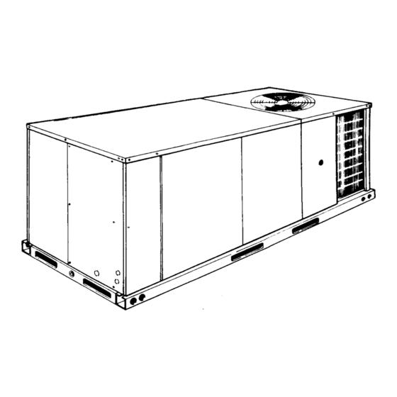
YORK Model DCE units are single package air conditioners
designed for outdoor installation on a rooftop or a slab. Electric
heaters are available as field-installed accessories.
The units are completely assembled on rigid, permanently
attached base rails. All piping, refrigerant charge, and electrical
wiring is factory-installed and tested. The units require only
electric power and duct connections at the point of installation.
The electric heaters have nickel-chrome elements and utilize
single point power connection.
INSPECTION
As soon as a unit is received, it should be inspected for possible
damage during transit. If damage is evident, the extent of the
damage should be noted on the carrier's freight bill. A separate
request for inspection by the carrier's agent should be made in
writing. Refer to Form 50.15-NM for additional information.
REFERENCE
Additional information on the design, installation, operation and
service of this equipment is available in the following reference forms:
•
55.70-N1
•
55.70-N2
•
530.18-N1.2V
Installer should pay particular attention to the words: NOTE, CAUTION and WARNING . Notes are intended to clarify or make
the installation easier. Cautions are given to prevent equipment damage. Warnings are given to alert installer that personal injury
and/or equipment damage may result if installation procedure is not handled properly.
THIS PRODUCT MUST BE INSTALLED IN STRICT COMPLIANCE WITH THE ENCLOSED INSTALLATION INSTRUCTIONS
AND ANY APPLICABLE LOCAL, STATE, AND NATIONAL CODES INCLUDING, BUT NOT LIMITED TO, BUILDING, ELECTRI-
CAL, AND MECHANICAL CODES
INCORRECT INSTALLATION MAY CREATE A CONDITION WHERE THE OPERATION OF THE PRODUCT COULD CAUSE
PERSONAL INJURY, PROPERTY DAMAGE AND/OR DEATH.
DE-ENERGIZE THE ELECTRICAL POWER TO THE UNIT BEFORE ATTEMPTING TO INSPECT, REPAIR OR PERFORM
MAINTENANCE TO THE UNIT.
Supersedes: 530.18-N7Y (993)
MODELS D4CE 036, 048 & 060 (10 SEER)
MODEL D2CE 072 (9 EER)
(STYLE B & Belt-Drive Option)
-General Installation
-Pre-start & Post-start Check List
-Economizer Accessory
SUNLINE 2000™
ELECTRIC / ELECTRIC
SINGLE PACKAGE AIR CONDITIONERS
•
530.18-N1.13V -Man. Outdoor Air Damper Accy 0-35%
•
530.18-N1.14V -Man. Outdoor Air Damper Accy 0-100%
•
530.18-N1.12V -Motorized Outdoor Air Damper Accy..
•
530.18-N1.8V
•
530.18-N7.1V
•
530.18-N7.2V
•
690.15-N25V
Renewal Parts:
•
Refer to Parts Manual for complete listing of replacement
parts on this equipment.
All forms referenced in this instruction may be ordered from:
Publications Distribution Center
Unitary Products Group
P.O. Box 1592, York, PA 17405
APPROVALS
Design certified by U.L. and C.G.A. as follows:
1. For use as a cooling only unit or cooling unit with electric heat.
2. For outdoor installation only.
3. For installation on combustible material.
CAUTION
WARNING
WARNING
530.18-N7Y (295)
-Coil Guard
-Electric Heater Accessory
-Fuse Block Accessory
-Low Ambient to 0°F
035-12855
Advertisement
Table of Contents

Related Manuals for York SUNLINE 2000


Summary of Contents for York SUNLINE 2000
-
Page 1: General
Switch two line voltage connections to correct. GENERAL • YORK Model DCE units are single package air conditioners 530.18-N1.13V -Man. Outdoor Air Damper Accy 0-35% • designed for outdoor installation on a rooftop or a slab. Electric 530.18-N1.14V -Man. Outdoor Air Damper Accy 0-100% heaters are available as field-installed accessories. -
Page 2: Table Of Contents
530.18-N7Y TABLE OF CONTENTS General ................1 TABLES Inspection................1 Description Page Reference ................1 Approvals ................1 Unit Application Data ........Nomenclature............... 2 Physical Data..........Blower Perf. - 3-6 Ton Direct-Drive ..... INSTALLATION Blower Perf. - 3 & 4 Ton Belt-Drive ..... Limitations ................ -
Page 3: Installation
CAUTION: If a unit is to be installed on a roof curb or special flanges only. DO NOT insert the screws through the frame other than a YORK roof curb, gasketing must casing. be applied to all surfaces that come in contact with the unit underside. -
Page 4: Condensate Drain
530.18-N7Y Electric Code (CEC) C22.1 (in Canada) and/or local CONDENSATE DRAIN ordinances. The unit must be electrically grounded in Plumbing must conform to local codes. Use a sealing accordance with the NEC and CEC (as specified above) and/or compound on male pipe threads. Install a condensate drain line local codes. -
Page 5: Optional Economizer Rain Hood
530.18-N7Y unit top cover. Then slip flange of hood cover in under flange OPTIONAL ECONOMIZER RAIN HOOD of unit top cover, replace screw (C), engaging hole (E) in The following procedure should be used when assembling an hood flange and tighten. Attach the two side plates to the economizer rain hood onto a unit. -
Page 6: Disconnect Switch Bracket For Optional Belt-Drive
530.18-N7Y Install the bracket on the left hand side of the unit as shown in DISCONNECT SWITCH BRACKET Figure 5. Several existing screws at the top of the unit and one FOR UNITS WITH OPTIONAL BELT-DRIVE BLOWER screw approximately midway down from the top will be used for mounting the bracket. -
Page 7: Maintenance
530.18-N7Y (Direct-Drive Units) FIELD-SUPPLIED BLOWER DISCONNECT SWITCH ACCESS LOCATION CONTROL FILTER ACCESS BOX ACCESS OUTDOOR COIL SCROLL COMPRESSOR ACCESS ⁄ FRONT VIEW ELECTRIC HEAT ⁄ ACCESS ⁄ “ PVC FEMALE COND. DRAIN ⁄ ⁄ (See Detail ”A") DUCT COVERS - Units are shipped with A, B all air duct ⁄... -
Page 8: Electric Heaters
530.18-N7Y FIG. 6 - ENTHALPY SET POINT ADJUSTMENT The heaters are wired for a single point power supply. Power ELECTRIC HEATERS supply need only be brought into the single point terminal block and thermostat wiring to the low voltage terminal strip located Electric heaters are available as field-installed accessories. -
Page 9: Blower Perf. - 3 & 4 Ton Belt-Drive
530.18-N7Y TABLE 4 - SUPPLY AIR PERFORMANCE - 3 & 4 TON w/Belt-Drive Blower 3 TON GAS HEAT VALUES SHOWN @ 230/460/575 VOLTS - Side Duct Connections Available External Static Pressure - IWG* UNIT AIR FLOW 0.20 0.30 0.40 0.50 0.60 0.70 0.80... -
Page 10: Blower Perf. - 5 & 6 Ton Belt-Drive
530.18-N7Y TABLE 5 - SUPPLY AIR PERFORMANCE - 5 & 6 TON w/Belt-Drive Blower 5 TON GAS HEAT VALUES SHOWN @ 230/460/575 VOLTS - Side Duct Connections Available External Static Pressure - IWG* UNIT AIR FLOW 0.20 0.30 0.40 0.50 0.60 0.70 0.80... -
Page 11: Static Resistances
530.18-N7Y TABLE 6 - STATIC RESISTANCES EXTERNAL STATIC PRESSURE DROP RESISTANCE, IWG DESCRIPTION 1000 1200 1400 1600 1800 2000 2200 2400 2600 2800 3000 1, 3 Economizer 0.07 0.08 0.09 0.11 0.13 0.15 0.17 0.20 0.23 0.26 0.30 5 - 15 KW 0.04 0.05 0.06... -
Page 12: Supperheat, 036
530.18-N7Y TABLE 10 - SUPERHEAT CHARGING TABLE FOR MODEL 036 SUPERHEAT AT SCROLL COMPRESSOR SUCTION, °F, AIRFLOW = 400 CFM/TON OUTDOOR TEMPERATURE, INDOOR WB TEMPERATURE, °F °F 25.6 26.8 29.2 30.4 31.6 32.8 33.3 33.9 34.4 34.9 20.1 21.7 23.3 24.9 26.5 28.1... -
Page 13: Supperheat, 072
530.18-N7Y TABLE 13 - SUPERHEAT CHARGING TABLE FOR MODEL 072 SUPERHEAT AT SCROLL COMPRESSOR SUCTION, °F, AIRFLOW = 400 CFM/TON OUTDOOR TEMPERATURE, INDOOR WB TEMPERATURE, °F °F 15.2 18.0 20.9 23.7 26.5 29.3 32.1 33.4 34.7 36.0 37.3 11.9 14.9 17.8 20.8 23.7... -
Page 14: Operation
530.18-N7Y OPERATION c. The thermostat will cycle the electric heat to satisfy the COOLING SYSTEM heating requirements of the conditioned space. The cooling section is a complete factory package utilizing an air-cooled condenser. The system is factory-charged with Two-Stage Heating: Refrigerant-22. -
Page 15: Secure Owner's Approval
530.18-N7Y The setting (turns open) for the optional belt-drive supply air To check the supply air CFM after the initial balancing has been motor pulley can be determined from Table 15. completed: TABLE 15 - BELT-DRIVE SUPPLY AIR ⁄ 1. Remove the (two) "... -
Page 16: Normal Maintenance
208/230, 460 VOLT MODELS ONLY MODELS ONLY 208/230-1-60 VOLT MODELS ONLY Unitary Products Group P.O. Box 1592, York, Pennsylvania USA 17405-1592 Subject to change without notice. Printed in U.S.A. 530.18-N7Y Copyright © by York International Corporation 1997. All Rights Reserved.
Need help?
Do you have a question about the SUNLINE 2000 and is the answer not in the manual?
Questions and answers