Sign In
Upload
Manuals
Brands
ZTE Manuals
Accessories
ZXSDR BS8908 G060
ZTE ZXSDR BS8908 G060 Manuals
Manuals and User Guides for ZTE ZXSDR BS8908 G060. We have
1
ZTE ZXSDR BS8908 G060 manual available for free PDF download: User Manual
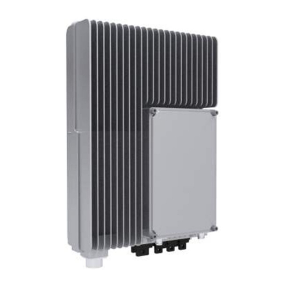
ZTE ZXSDR BS8908 G060 User Manual (80 pages)
Outdoor GSM Mode Micro BTS
Brand:
ZTE
| Category:
Accessories
| Size: 3.74 MB
Table of Contents
Table of Contents
3
Chapter 1 System Overview
7
System Background
7
System Position
7
System Position in Network
7
Figure 1-1 BS8908 Position in GSM Network
8
System Position in Distributed Base Station
9
Figure 1-2 Base Station (BBU+RRU)
9
Cabinet Appearance
10
Figure 1-3 Distributed Base Station System Structure
10
Figure 1-4 Cabinet Appearance
10
Product Features
11
Services and Functions
11
Operation and Maintenance
12
Figure 1-5 BS8908 Operation and Maintenance
13
Chapter 2 System Indices
15
Physical Indices of RRU
15
Radio Performance Indices
16
Interface and Transmission Indices
16
Chapter 3 System Structure and Principles
19
Structure and Layout
19
External Interfaces
19
Figure 3-1 External Interfaces at Cabinet Bottom
19
Table 3-1 External Interfaces
19
Equipment Indicators
20
Figure 3-2 BS8908 Indicators
20
Table 3-2 Indicators and Buttons
21
Hardware Subsystem
22
Hardware Architecture
22
Figure 3-3 BS8908 Hardware System
22
Table 3-3 Cabinet Hardware Composition
22
Module Functions
23
Software Subsystem
24
Software Architecture
24
Software Functions
24
Figure 3-4 BS8908 Software Architecture
24
Chapter 4 Networking and Configuration
27
Networking
27
Star Networking
27
Cascading Networking
27
Figure 4-1 Star Networking
27
Configuration
28
Configuration Principles
28
Typical Configurations
28
Figure 4-2 Cascading Networking
28
Figure 4-3 O2 ~ O4 Configuration
28
Table 4-1 Typical System Configuration Specifications
28
Figure 4-4 O5 ~ O8 Configuration
29
Figure 4-5 O9 ~ O12 Configuration
29
Figure 4-6 RRU Function Configuration Diagram
30
Figure 4-7 BBU Function Configuration Diagram
30
Chapter 5 Installation
31
Safety Instructions
31
Safety Instructions Overview
31
Safety Symbols
31
Table 5-1 Safety Symbols and Meanings
31
Safety Instructions Guideline
33
Installation Preparations
35
Installation Environment Check
35
Table 5-2 Working Temperature and Humidity Requirement for BS8908
35
Personnel
36
Tools and Instruments Preparation
36
Table 5-3 Tools and Instruments
37
Unpacking and Inspection
38
Packing Box of BS8908
38
Unpacking and Inspection Flow
39
Figure 5-1 Package of BS8908
39
Installation Overview
40
Installation Flow
40
Figure 5-2 Unpacking and Inspection Flow
40
Hoisting Operation Precautions
41
Figure 5-3 BS8908 Installation Flow
41
Installation Modes and Installation Accessories
42
Installing Accessories
42
Table 5-4 BS8908 Installation Accessories and Functions
42
Wall-Mounted Installation Mode
43
Pole-Mounted Installation Mode
44
Figure 5-4 Wall-Mounted Installation of BS8908
44
Figure 5-5 Installing One BS8908 on Pole
45
Figure 5-6 Installing Two Bs8908S on Pole
46
Slot Steel Installation Mode and Equilateral Angle Steel Installation Mode
47
Figure 5-7 Installing Three Bs8908S on Pole
47
R8860 Installation
48
Installing BS8908 on the Wall
48
Figure 5-8 Drilling Template
48
Figure 5-9 Installing Wall-Mounted Installation Component
49
Figure 5-10 Groove Schematic Diagram
49
Pole-Mounted Installation (with Pole Fixing Plate)
50
Figure 5-11 Fixing Cabinet
50
Figure 5-12 Assembling Wall-Mounted+Pole-Mounted Component
51
Figure 5-13 Installing Pole Fixing Plate
51
Figure 5-14 Fixing Cabinet
52
Figure 5-15 Assembling Wall-Mounted+Pole-Mounted Component
52
Figure 5-16 Installing Wall-Mounted+Pole-Mounted Component
53
Figure 5-17 Fixing Cabinet
53
Figure 5-18 Assembling Wall-Mounted+Pole-Mounted Component
54
Figure 5-19 Installing Wall-Mounted+Pole-Mounted Component
54
Installing Cable Rack
55
Figure 5-20 Installing the Third Wall-Mounted Installation Component
55
Figure 5-21 Fixing Cabinet
55
Figure 5-22 Installing Cable Rack
56
Installing Lightning Protection Box
57
Figure 5-23 Installed Cable Rack
57
Figure 5-24 Installing Lightning-Protection-Box Installation Component
58
Figure 5-25 Installing Lightning Protection Box
59
External Cable Installation
60
External Cable Connections
60
Figure 5-26 Installed Lightning Protection Box
60
Table 5-5 External Cable Connections of BS8908
60
External Cable Installation Flow
62
Installing Power Cable
63
Figure 5-27 External Cable Installation Flow
63
Figure 5-28 DC Power Cable Structure
64
Table 5-6 DC Power Cable Cores
64
Installing Grounding Cable
65
Figure 5-29 AC Power Cable Structure
65
Table 5-7 AC Power Cable Cores
65
Installing Abis E1 Cable
66
Figure 5-30 Grounding Cable Structure
66
Figure 5-31 Copper Bar of Grounding Network
66
Figure 5-32 E1 Cable
67
Table 5-8 Description of Cores of E1 Cable for Abis
67
Installing Abis Ethernet Cable
68
Figure 5-33 Abis Ethernet Cable
68
Installing Fiber Connecting RRU
69
Figure 5-34 Fiber Connecting RRU
69
Installing Environment Monitoring Cable
70
Figure 5-35 Environment Monitoring Cable
70
Table 5-9 Core Color and Signal Description
70
Installing AISG Control Cable
71
Figure 5-36 AISG Control Cable Structure
71
Installing GPS Cable
72
Installing Antenna Feeder Jumper
72
Figure 5-37 Antenna Feeder Jumper Installation Position
73
Figures
75
Advertisement
Advertisement
Related Products
Zte ZXSDR BS8900A GU360
Zte ZXSDR BS8800
ZTE ZXSDR BS8800 C200
Zte ZXSDR R8882
ZTE ZXSDR R8978
ZTE ZXSDR R8882 L268
ZTE ZXSDR R8881 S4200
ZTE ZXSDR BS8900
Zte ZXSDR BS8800 C100
ZTE ZXSDR BS8802 C100
ZTE Categories
Cell Phone
Modem
Wireless Router
Network Router
Switch
More ZTE Manuals
Login
Sign In
OR
Sign in with Facebook
Sign in with Google
Upload manual
Upload from disk
Upload from URL