Oriental motor DSC Series Operating Manual
Speed control motor and controller package electromagnetic brake type
Hide thumbs
Also See for DSC Series:
- Operating manual (44 pages) ,
- Operating manual (40 pages) ,
- Operating manual (44 pages)
Table of Contents
Advertisement
Quick Links
Speed Control Motor and Controller Package
DSC Series
Electromagnetic brake type
OPERATING MANUAL
Thank you for purchasing an Oriental Motor product.
This Operating Manual describes product handling procedures and safety precautions.
• Please read it thoroughly to ensure safe operation.
• Always keep the manual where it is readily available.
D-loop represents the speed control motor which adopted Oriental
Motor's unique technology.
This product achieves high reliability using closed loop control in
addition to downsize the speed controller by digitizing the phase
control circuit.
HM-9346-3
Advertisement
Table of Contents

Subscribe to Our Youtube Channel
Related Manuals for Oriental motor DSC Series


Summary of Contents for Oriental motor DSC Series
- Page 1 HM-9346-3 Speed Control Motor and Controller Package DSC Series Electromagnetic brake type OPERATING MANUAL Thank you for purchasing an Oriental Motor product. This Operating Manual describes product handling procedures and safety precautions. • Please read it thoroughly to ensure safe operation.
-
Page 2: Table Of Contents
Table of contents 1 Introduction ..........3 6.6 Timing chart ........... 22 6.7 Operating cycle ........23 2 Safety precautions .......4 „ Limitation in vertical operation....23 „ 3 Preparation ..........5 6.8 Brake current ......... 23 3.1 Checking the product ......5 6.9 Operating in vertical direction .... -
Page 3: Introduction
Introduction 1 Introduction „ Before use Only qualified and educated personnel should work with the product. Use the product correctly after thoroughly reading the section "2 Safety precautions" on.p.4. The items under Note contain important handling instructions that the user should observe to ensure safe use of the product. -
Page 4: Safety Precautions
Safety precautions 2 Safety precautions The precautions described below are intended to prevent danger or injury to the user and other personnel through safe, correct use of the product. Use the product only after carefully reading and fully understanding these instructions. Handling the product without observing the instructions that accompany a “Warning”... -
Page 5: Preparation
Preparation 3 Preparation 3.1 Checking the product Verify that the items listed below are included. Report any missing or damaged items to the branch or sales office from which you purchased the product. Verify the model number of the purchased product against the number shown on the package label. Check the model number of the motor, gearhead and speed controller against the number shown on the nameplate. -
Page 6: List Of Combinations
Preparation 3.3 List of combinations Model names for motor, gearhead and speed controller are shown below. Enter the gear ratio in the box ( o ) within the model name. Enter the cable length (-1, -2, -3) in the box ( „ ) within the model name when the connection cable is supplied. Add "V"... -
Page 7: Names And Functions Of Parts
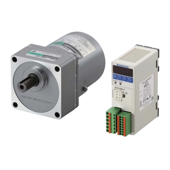
Preparation 3.4 Names and functions of parts „ Motor Electromagnetic brake Tachogenerator Output shaft Motor Protective Earth Terminal Gearhead Mounting holes Rear view of the motor (four locations) „ Speed controller Display Operation panel Operation keys Protective film POWER LED (Use after removing the protective film.) (Green) ALARM LED... -
Page 8: Installation
Installation 4 Installation This chapter explains the installation location and installation methods. 4.1 Location for installation The motor and speed controller described in this manual have been designed and manufactured to be incorporated in general industrial equipment. Install them in a well-ventilated location that provides easy access for inspection. •... -
Page 9: X84; Removing / Installing The Gearhead
Installation „ Removing / Installing the gearhead The gearhead or the outlet position of the motor lead wires can be changed. • Removing the gearhead from the motor Remove the gearhead by unscrewing the hexagonal socket-head screws holding the gearhead to the motor (2 locations). Illustration shows the view from motor case side. -
Page 10: Installing A Load
Installation 4.3 Installing a load When installing a load on the gearhead, pay attention to the following points. • Align the centerline of the gearhead output shaft with the centerline of the load. • A key slot is provided on the output shaft of the gearhead. Form a key slot on the load side and secure the load using the supplied parallel key. -
Page 11: Installing The Speed Controller
Installation 4.5 Installing the speed controller The speed controller is designed so that heat is dissipated via air convection. Provide spaces so that the speed controller can be ventilated well through its top and bottom vent holes. • Vertical direction •... -
Page 12: Installing The Capacitor
Installation 4.6 Installing the capacitor Mount the capacitor securely using M4 screw (not provided). Ø4.3 mm (0.169 in.) Note • Do not let the screw fastening torque exceed 1 N·m (8.8 lb-in) to prevent damage to the mounting foot. • Install the capacitor apart from the motor. If it is located closer, the capacitor life may be shortened due to the heat of the motor. -
Page 13: Connection
Connection 5 Connection This chapter explains how to connect the speed controller, power supply, motor and others. When operating a motor, be sure to connect the control DC power supply in addition to the AC power supply. 5.1 Connecting method Motor Speed controller Control DC power supply... -
Page 14: Connecting The Ac Power Supply And Capacitor
Connection 5.2 Connecting the AC power supply and capacitor Connect the AC power supply and capacitor to the CN1 on the speed controller. • Applicable cable size: AWG18 to 14 (0.75 to 2.0 mm • Lead wire strip length: 10 mm (0.39 in.) If crimp terminals are used, select the following terminals. -
Page 15: Connecting The Control Dc Power Supply And I/O Signals
Connection 5.5 Connecting the control DC power supply and I/O signals Connect the control power supply and I/O signals to the CN4. For the control DC power supply, use a power supply with reinforced insulation on its primary and secondary sides. •... - Page 16 Connection „ Internal circuit configuration of signal input part All input signals of the speed controller are photocoupler inputs. +24 V SINK SOURCE Pin No. 4.7 kΩ 3 to 8 „ Internal circuit configuration of signal output part All output signals of the speed controller are photocoupler/ open-collector output.
-
Page 17: Connection Example For I/O Signals And Programmable Controller
Connection 5.6 Connection example for I/O signals and programmable controller Figure seen from the lower face of Set the input logic to the "sink logic" side or "source logic" side in accordance the speed controller with the programmable controller used with the speed controller. It is set using the SW1 as shown in the figure. -
Page 18: Operation
Operation 6 Operation This product can be used for a vertical operation such as elevating equipment in addition to a horizontal operation such as conveyor transportation. Vertical operation When using the motor in an application that a load is driven vertically or the motor output shaft is forcibly rotated by a load as shown in the figure, use in the following operating conditions. -
Page 19: X84; Test Operation
Operation „ Test operation The connection between the motor and speed controller can be checked. When performing test operation, do not install a load to the motor. The rotation speed in test operation is 300 r/min. Operation Display on the operation panel Power ON Press the... -
Page 20: Setting The Rotation Speed
Operation 6.3 Setting the rotation speed The rotation speed can be set using any of the following method (1), (2) or (3). The rotation speed of the gearhead output shaft varies depending on the gear ratio. This manual describes the rotation speed of the motor output shaft. -
Page 21: X84; Remote Setting Method
Operation „ Remote setting method The rotation speed can also be set remotely by the following two methods. Set the "external speed command input" parameter to "ON (Enable)" (initial value: OFF), and turn the M0 input and M1 input OFF. The setting range of the rotation speed varies depending on the setting of the "deceleration control"... -
Page 22: Motor Rotation Direction
Operation 6.5 Motor rotation direction • The rotation direction shown in the figure below is as viewed from the motor output shaft. • The rotation direction of the gearhead output shaft varies depending on the gear ratio of the gearhead. Use the FWD input or REV input according to the gear ratio of the gearhead. -
Page 23: Operating Cycle
Operation 6.7 Operating cycle If operations such as running and instantaneous stop or instantaneous rotation direction changes are repeated in a short cycle time, the motor temperature rise will be large, and the operating time may be limited. Use the motor by reference to the followings. -
Page 24: Operating In Vertical Direction
Operation 6.9 Operating in vertical direction This product can be used in the mechanism of vertical operation such as elevating equipment. Check the following conditions thoroughly before using the product. „ Notes about vertical operation • If the product is used in vertical operation, provide the safety device for anti-drop mechanism in equipment side. -
Page 25: Operating In Two Or More Speed (Multi-Speed Operation)
Operation 6.10 Operating in two or more speed (multi-speed operation) The multi-speed operation can be performed by setting Low speed the rotation speed and switching the ON/OFF status of the M0 and M1 inputs. High speed „ Data setting method (Example: Rotation speed) Power ON Display on the operation panel... -
Page 26: Adjusting The Rotation Speed Of Two Or More Motors By A Single Speed Setter (Multi-Motor Control)
Operation 6.11 Adjusting the rotation speed of two or more motors by a single speed setter (multi-motor control) Two or more motors can be operated at the same speed using a single variable resistor or external DC voltage. Set the "external speed command input" parameter to "ON (Enable)," and turn the M0 input and M1 input OFF. Refer to p.31 for parameters. -
Page 27: Function
Function 7 Function 7.1 Functions list The following functions are available for this product. Reference Function Description page Displays the rotation speed of the motor output shaft. Displays by the rotation speed of the gearhead output Rotation speed shaft. Fixes the display of the lowest digit to "0." Displays by the transfer speed of the conveyor drive. -
Page 28: Setting Items And Panel Displays
Function 7.2 Setting items and panel displays Power ON Power ON • When turning on the AC power supply, the POWER LED (green) is lit. • When turning on the DC power supply, the display on the operation panel is lit. Rotation speed teaching function Rotation speed... - Page 29 Function Operation panel Edit lock function The operation panel can be locked so that the data cannot be changed. : Switches the operation mode. Moves to the upper level. Perform the following action on the top screen. Lock ∗: Press and hold for 5 seconds : Changes the setting value.
-
Page 30: Items Which Can Be Monitored
Function 7.3 Items which can be monitored Operation mode: Monitor mode Item Display Description • The motor rotation speed is displayed. • When the "speed reduction ratio" parameter is set, the rotation speed of the gear Rotation speed output shaft or the conveyor transfer speed is displayed. •... -
Page 31: Setting The Parameters
Function 7.5 Setting the parameters „ Parameter list Operation mode: Parameter mode Initial Item Display Description Setting range value When setting the gear ratio of the gearhead, the speed being converted by the speed reduction ratio can be displayed. If Gr-r Speed reduction ratio 1.00 to 9999... -
Page 32: X84; Displayed Digit Number When Setting The Speed Reduction Ratio Or Speed Increasing Ratio
Function „ Displayed digit number when setting the speed reduction ratio or speed increasing ratio Since the number of significant figures for the integer part is changed if the speed reduction ratio or speed increasing ratio is set, the digit number displayed on the panel will also be changed. Setting value for the speed reduction Display digit on the panel ratio and speed increasing ratio... -
Page 33: X84; Stop Mode Selection
Function „ Stop mode selection Any of instantaneous stop, deceleration stop, and coasting stop can be used to stop the motor. If both the FWD input and REV input are turned ON, the motor stops instantaneously. Select how the motor should stop when turning the FWD input or REV input to OFF from ON. "Brake type"... -
Page 34: X84; Description Of I/O Signals Which Can Be Assigned
Function „ Description of I/O signals which can be assigned 6 input signals and 2 output signals out of the following signals can be assigned. Signal Terminal Signal name Description When the FWD input is turned ON, the motor output shaft rotates in the forward direction based on the set acceleration time. -
Page 35: Alarm And Warning
Alarm and warning 8 Alarm and warning The speed controller provides alarms that are designed to protect the speed controller from overheating, poor connection, error in operation, etc. (protective functions), as well as warnings that are output before the corresponding alarms generate (warning functions). -
Page 36: Warning
Alarm and warning • Reset using the ALARM-RESET input Turn both the FWD input and REV input OFF before turning the ALRM-RESET input ON. The ALARM-RESET input is disabled while the FWD input or REV input is being ON. The figure shows an example for the FWD input. Rotation Stop Motor movement... -
Page 37: Troubleshooting And Remedial Actions
Troubleshooting and remedial actions 9 Troubleshooting and remedial actions During motor operation, the motor or speed controller may fail to function properly due to an improper rotation speed setting or wiring. When the motor cannot be operated correctly, refer to the contents provided in this section and take appropriate action. If the problem persists, contact your nearest Oriental Motor sales office. -
Page 38: Inspection
Inspection 10 Inspection It is recommended that periodic inspections for the items listed below are conducted after each operation of the motor. If an abnormal condition is noted, discontinue any use and contact your nearest Oriental Motor sales office. Note •... -
Page 39: Standard And Ce Marking
Standard and CE Marking 11 Standard and CE Marking 11.1 Standard and CE Marking This product is recognized by UL under the UL and CSA standards, and it conforms to the China Compulsory Certification System (CCC System). This product is also affixed the CE Marking under the Low Voltage Directive and EMC Directive. -
Page 40: Installing And Wiring In Compliance With Emc Directive
Standard and CE Marking „ EMC Directive This product has received EMC compliance under the conditions specified in "Example of motor and driver installation and wiring" on.p.41. Since the final level of conformance of the machinery equipment to the EMC Directive will vary depending on such factors as the configuration, wiring, layout and risk involved in the control-system devices and electrical parts that are used with the motor/speed controller, the customer must conduct the EMC tests on the machinery equipment to confirm compliance. - Page 41 Standard and CE Marking „ Notes about installation and wiring • Connect the motor, speed controller and other peripheral control equipment directly to the grounding point so as to prevent a potential difference from developing between grounds. • When relays or electromagnetic switches are used together with the system, use mains filters and CR circuits to suppress surges generated by them.
-
Page 42: General Specifications
General specifications 12 General specifications Item Motor Speed controller Single-phase 100V, Single-phase 200V: −10 to +50 °C [+14 to +122 °F] Ambient (non-freezing) 0 to +40 °C [+32 to +104 °F] temperature Single-phase 110/115V, (non-freezing) Single-phase220/230V: −10 to +40 °C [+14 to +104 °F] (non-freezing) Ambient 85% or less (non-condensing) -
Page 43: Accessories (Sold Separately)
Accessories (sold separately) 13 Accessories (sold separately) „ Connection cables These cables are used to extend the wiring distance between the speed controller and motor. Flexible connection cables are also available. The wiring distance can be extended to a maximum of 10.5 m (34.4 ft.). •... - Page 44 • Please contact your nearest Oriental Motor o ce for further information. Singapore Korea Technical Support Tel:(800)468-3982 Tel:1800-8420280 Tel:080-777-2042 8:30 to 5:00 , P.S.T. (M-F) A.M. P.M. www.orientalmotor.com.sg www.inaom.co.kr 7:30 to 5:00 , C.S.T. (M-F) A.M. P.M. www.orientalmotor.com Tel:1800-806161 Hong Kong Branch Tel:+55-11-3266-6018 www.orientalmotor.com.my...
Need help?
Do you have a question about the DSC Series and is the answer not in the manual?
Questions and answers