
Related Manuals for H3C MSR830 Series


Summary of Contents for H3C MSR830 Series
- Page 1 H3C MSR830 Router Series Installation Guide New H3C Technologies Co., Ltd. http://www.h3c.com Document version: 6W100-20180818...
- Page 2 The information in this document is subject to change without notice. All contents in this document, including statements, information, and recommendations, are believed to be accurate, but they are presented without warranty of any kind, express or implied. H3C shall not be liable for technical or editorial errors or omissions contained herein.
- Page 3 Preface The H3C MSR830 Router Series Installation Guide includes seven chapters, which describe the preparing for installation, installing the router, replacement procedure, troubleshooting, chassis views and technical specifications, LEDs, and slot arrangement. This preface includes the following topics about the documentation: •...
- Page 4 Convention Description Multi-level menus are separated by angle brackets. For example, File > Create > > Folder. Symbols Convention Description An alert that calls attention to important information that if not understood or followed WARNING! can result in personal injury. An alert that calls attention to important information that if not understood or followed CAUTION: can result in data loss, data corruption, or damage to hardware or software.
- Page 5 It is normal that the port numbers, sample output, screenshots, and other information in the examples differ from what you have on your device. Documentation feedback You can e-mail your comments about product documentation to info@h3c.com. We appreciate your comments.
-
Page 6: Table Of Contents
Contents Preparing for installation ···································································· 1 Safety recommendations ············································································································· 1 Safety symbols ··················································································································· 1 General safety recommendations ··························································································· 1 Electricity safety ·················································································································· 1 Examining the installation site ······································································································· 1 Temperature and humidity ····································································································· 2 ... - Page 7 MSR830-6EI-GL ··············································································································· 24 MSR830-6HI-GL ··············································································································· 24 MSR830-10HI-GL ·············································································································· 25 MSR830-10EI-GL ·············································································································· 25 Technical specifications ············································································································· 26 Appendix B LEDs ··········································································· 27 Panel LEDs ···························································································································· 27 MSR830-6EI-GL ··············································································································· 27 MSR830-6HI-GL ··············································································································· 27 MSR830-10HI-GL ··············································································································...
-
Page 8: Preparing For Installation
Preparing for installation Figure 1 This document applies to the following device models: Model Product code MSR830-6EI-GL RT-MSR830-6EI-GL MSR830-6HI-GL RT-MSR830-6HI-GL MSR830-10HI-GL RT-MSR830-10HI-GL MSR830-10EI-GL RT-MSR830-10EI-GL Safety recommendations Safety symbols When reading this document, note the following symbols: WARNING means an alert that calls attention to important information that if not understood or followed can result in personal injury. -
Page 9: Temperature And Humidity
Temperature and humidity Maintain temperature and humidity in the equipment room at acceptable levels. • Lasting high relative humidity tends to cause poor insulation, electricity leakage, mechanical property change of materials, and corrosion of metal parts. • Lasting low relative humidity is likely to result in loose screws due to washer contraction, and even ESD, which causes the circuits to fail. -
Page 10: Esd Prevention
ESD prevention CAUTION: Check the resistance of the ESD wrist strap for safety. The resistance reading must be in the range of 1 to 10 megohm (Mohm) between human body and the ground. To prevent electrostatic discharge (ESD), follow these guidelines: •... -
Page 11: Rack-Mounting
Rack-mounting Before mounting the router in a standard 19-inch rack, adhere to the following requirements: • The rack is equipped with a good ventilation system. • The rack is sturdy enough to support the router and its accessories. • For heat dissipation and device maintenance, make sure the front and rear of the rack are at least 0.8 m (2.62 ft) away from walls or other devices, and the headroom in the equipment room is no less than 3 m (9.84 ft). -
Page 12: Pre-Installation Checklist
Pre-installation checklist Table 4 Pre-installation checklist Item Requirements Result • There is a minimum clearance of 100 mm (3.94 in) around the inlet and outlet vents for heat dissipation of the router chassis. Ventilation • A good ventilation system is available at the installation site. -
Page 13: Installing The Router
• Keep the tamper-proof seal on a mounting screw on the chassis cover intact, and if you want to open the chassis, contact H3C for permission. Otherwise, H3C shall not be liable for any consequence. - Page 14 Figure 2 Installation flow Start Workbench-mounting Rack-mounting Determine the installation position Mount the router on a Mount the router in a rack workbench Ground the router Install a Micro SD card Install a USB drive Connect interface cables Connect the router to a configuration terminal Connect the power cord Verify the installation...
-
Page 15: Installing The Router
Installing the router Mounting the router on a workbench IMPORTANT: • Ensure good ventilation and 100 mm (3.94 in) of clearance around the chassis for heat dissipation. • Do not place heavy objects on the router. To mount the router on a workbench: Make sure the workbench is clean, stable, and correctly grounded. - Page 16 To install the router in a rack: Use a mounting bracket to mark the positions of cage nuts on the front rack posts. Make sure the cage nut installation holes on the front rack posts are on a horizontal line. Install cage nuts, as shown in Figure 5.
-
Page 17: Grounding The Router
Figure 7 Securing the router to the rack Grounding the router WARNING! Correctly connecting the router grounding cable is crucial to lightning protection and EMI protection. IMPORTANT: The resistance reading must be smaller than 5 ohms between the chassis and the ground. Attaching the ring terminal to the grounding cable The router comes with a ring terminal. -
Page 18: Grounding The Router With A Grounding Strip
Figure 8 Attaching the ring terminal to the grounding cable Grounding the router with a grounding strip Remove the grounding screw from the grounding hole on the rear panel of the chassis. Use the grounding screw to attach the ring terminal of the grounding cable to the grounding hole. -
Page 19: Installing A Micro Sd Card
Remove the nut from the grounding post of the grounding point on the rack. Use the needle-nose pliers to bend a hook at the other end of the grounding cable, and use the removed nut to attach the hook to the grounding post. Figure 10 Grounding the router through the rack Installing a Micro SD card CAUTION:... -
Page 20: Connecting A Usb Drive
Figure 11 Installing a Micro SD card Connecting a USB drive Connect a USB drive to the USB port of the router as shown in Figure Figure 12 Connecting a USB drive Connecting interface cables Connecting an AC power cord Make sure the router is correctly grounded. -
Page 21: Connecting An Ethernet Cable
Figure 13 Connecting an AC power cord Connecting an Ethernet cable Connect one end of the cable to an Ethernet port on the router and the other end to an Ethernet port on the peer device. Examine the port LED on the router. For more information about the LEDs, see "LED description."... -
Page 22: Connecting An Optical Fiber
Connecting an optical fiber WARNING! Do not stare into any fiber port when you connect an optical fiber. The laser light emitted from the optical fiber might hurt your eyes. CAUTION: • To connect a fiber port by using an optical fiber, first install a transceiver module in the port and then connect the optical fiber to the transceiver module. -
Page 23: Connecting The Console Cable And Setting Terminal Parameters
Connecting the console cable and setting terminal parameters To access the router at the first time, you can only use a console cable to connect the console port on the router to a configuration terminal. Connecting the console cable IMPORTANT: •... -
Page 24: Verifying The Installation
System is starting... Press Ctrl+D to access BASIC-BOOTWARE MENU Booting Normal Extended BootWare **************************************************************************** H3C MSR830 BootWare, Version 1.12 **************************************************************************** Copyright (c) 2004-2017 New H3C Technologies Co., Ltd. Compiled Date : Jun 20 2017 CPU ID : 0xc CPU L1 Cache... - Page 25 Cryptographic algorithms tests passed. Line con0 is available. Press ENTER to get started. Press Enter. The router is ready to configure when you see the following prompt: <H3C> Configure basic settings for the router. For more information, see the relevant documents.
-
Page 26: Replacement Procedure
• Keep the tamper-proof seal on a mounting screw on the chassis cover intact, and if you want to open the chassis, contact H3C for permission. Otherwise, H3C shall not be liable for any consequence. -
Page 27: Replacing A Transceiver Module
Replacing a transceiver module Gently open the clasp on the transceiver module. If the clasp is obstructed and you cannot use your finger to open it, use a pair of flat-head tweezers to open it. Hold the clasp and pull the transceiver module slowly out of the fiber port. Insert a dust plug into the transceiver module port and keep the removed transceiver module secure. -
Page 28: Troubleshooting
• Keep the tamper-proof seal on a mounting screw on the chassis cover intact, and if you want to open the chassis, contact H3C for permission. Otherwise, H3C shall not be liable for any consequence. -
Page 29: Garbled Terminal Display
Terminal emulation—VT100 Verify that the console cable is in good condition. If the issue persists, contact H3C Support. Garbled terminal display Symptom The configuration terminal displays garbled characters when the router is powered on. Solution Verify that the Data bits field is set to 8 for the configuration terminal. If the Data bits field is set to 5 or 6, the configuration terminal displays garbled characters. -
Page 30: Scenario 3
If you have saved some configurations, you can use the CLI to delete the configuration file or press the RESET button for more than 4 seconds to restore the factory settings. Scenario 3 Symptom The router crashes. Solution Press the RESET button for a short time to reboot the router. Reset button usage guidelines You can use the button to reboot the system or restore the factory settings. -
Page 31: Appendix A Chassis Views And Technical Specifications
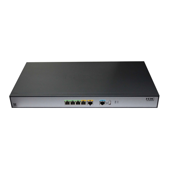
Appendix A Chassis views and technical specifications Chassis views The following figures are for illustration only. MSR830-6EI-GL Figure 19 MSR830-6EI-GL front view (1) Console port (2) Reset button (3) Gigabit Ethernet LAN/WAN ports (GE2 to GE5) (4) Gigabit Ethernet WAN ports (GE0 and GE1) Figure 20 MSR830-6EI-GL rear view (1) Grounding terminal (2) AC-input power receptacle... -
Page 32: Msr830-10Hi-Gl
Figure 22 MSR830-6HI-GL rear view (1) Grounding terminal (2) AC-input power receptacle MSR830-10HI-GL Figure 23 MSR830-10HI-GL front view (1) Console port (2) USB port (3) Micro SD card slot (4) Reset button (5) Combo interface 3 (6) Gigabit Ethernet WAN ports (GE0 to GE2) (7) Gigabit Ethernet LAN/WAN ports (GE4 to GE9) Figure 24 MSR830-10HI-GL rear view (1) Grounding terminal... -
Page 33: Technical Specifications
Figure 26 MSR830-10EI-GL rear view (1) Grounding terminal (2) AC-input power receptacle Technical specifications Table 5 Technical specifications (1) Item MSR830-6EI-GL MSR830-10EI-GL MSR830-6HI-GL MSR830-10HI-GL Console ports USB ports GE copper ports SFP ports Micro SD slots Reset button Memory 1GB DDR3 1GB DDR3 1GB DDR3 1GB DDR3... -
Page 34: Appendix B Leds
Appendix B LEDs Panel LEDs MSR830-6EI-GL Figure 27 MSR830-6EI-GL LEDs (1) Gigabit Ethernet port yellow LED (2) Gigabit Ethernet port green LED (3) System status LED (SYS) (4) VPN status LED MSR830-6HI-GL Figure 28 MSR830-6HI-GL LEDs (1) Gigabit Ethernet port yellow LED (2) Gigabit Ethernet port green LED (3) System status LED (SYS) (4) VPN status LED... -
Page 35: Msr830-10Hi-Gl
MSR830-10HI-GL Figure 29 MSR830-10HI-GL LEDs (1) Gigabit Ethernet port yellow LED (2) Gigabit Ethernet port green LED (3) System status LED (SYS) (4) VPN status LED (5) Micro SD card LED (6) Combo interface LED (7) Gigabit Ethernet port LED MSR830-10EI-GL Figure 30 MSR830-10EI-GL LEDs (1) Gigabit Ethernet port yellow LED... - Page 36 LEDs State Description Steady green The SDRAM is performing self-test. The system software image is being copied and Flashing green (8 Hz) decompressed. Comware has started with the configuration file and the router Flashing green (1 Hz) has booted up. System status LED (SYS) Flashing yellow (1 Hz)
-
Page 37: Index
Index A C E G I L M N R S T Mounting the router on a workbench,8 MSR830-10EI-GL,25 Attaching the ring terminal to the grounding cable,10 MSR830-10EI-GL,28 MSR830-10HI-GL,25 MSR830-10HI-GL,28 Cleanliness,2 MSR830-6EI-GL,27 Connecting an AC power cord,13 MSR830-6EI-GL,24 Connecting an Ethernet cable,14 MSR830-6HI-GL,24 Connecting an optical...
Need help?
Do you have a question about the MSR830 Series and is the answer not in the manual?
Questions and answers