Table of Contents
Advertisement
Available languages
Available languages
Quick Links
Download this manual
See also:
Manual
Advertisement
Chapters
Table of Contents

Related Manuals for RTW TouchMonitor TM3


Summary of Contents for RTW TouchMonitor TM3
- Page 1 TouchMonitor TM3 Manual...
- Page 2 Software Version 1.nn | 05.2012 • TM3 • TM3-SOLO • TM3-6CH © 2012 | RTW GmbH & Co.KG Am Wassermann 25 | 50829 Köln | Germany Fon +49 221. 70 913-0 | Fax +49 221. 70 913-32 www.rtw.de | rtw@rtw.de Manual | TM3...
- Page 3 TouchMonitor TM3 Bedienungsanleitung...
- Page 4 Bedienungsanleitung für RTW TouchMonitor TM3 Serie • TM3 • TM3-SOLO • TM3-6CH Manual-Version: Erstellt: 25.05. 2012 Software-Version: 1.42 und höher | 24.05.2012 © 2012 | Technische Änderungen vorbehalten! RTW GmbH & Co.KG | Am Wassermann 25 | 50829 Köln | Germany Fon +49 221. 70 913-0 | Fax +49 221. 70 913-32 www.rtw.de | rtw@rtw.de WEEE-Reg.-Nr.: DE 90666819 Kategorie: Geräteart: Diese Geräte erfüllen als Überwachungs- und Kontroll- instrumente in der Kategorie 9, Anhang 1B, die Vor- schriften des Elektro- und Elektronikgesetzes vom 16. März 2005 und der RoHS-Directive 2002/95/EC. Hinweise: • Die in dieser Bedienungsanleitung enthaltenen Informationen geben den Stand bei der Veröffentlichung wider. Die Abbildungen dienen der...
- Page 5 Sicherheitshinweise Die folgenden Symbole sind auf dem Gehäuse des Gerätes, auf einzel- nen Modulen und in dieser Bedienungsanleitung zu finden: WaRnung! Dieses Symbol warnt Sie vor einer möglicherweise gefährlichen Situation, etwa vor gefährlichen Spannungen, die Sie einem elektrischen Schock aussetzen könnten. Achten Sie auf den Warnhinweis und handeln Sie besonders vorsichtig. acHTung! Dieses Symbol macht Sie auf wichtige Bedienhinweise oder auf mögliche Bedienfehler aufmerksam, die zur Beschädigung von Geräten führen könnten. Wenn Sie dieses Zeichen auf einem Gerät finden, beachten Sie die Hinweise in der Bedienungsanleitung zu entsprechenden Vorsichts- maßnahmen. HinWeiS Dieses Symbol weist Sie auf Besonderheiten hin, bei denen es sich nicht um Fehlfunktionen handelt. Manual | TM3 Sicherheitshinweise DE-3...
-
Page 6: Allgemeine Sicherheitsanweisungen
• Befolgen Sie immer diesen Anweisungen, um Schaden für sich, am Gerät oder an angeschlossenen Geräten zu vermeiden! Um einen möglichen Stromschlag, Brand, Schaden oder Fehlfunk- tionen zu verhindern, benutzen Sie bitte das Gerät nur wie vorgesehen. Die Geräte sind für den Einsatz in geschlossenen Räumen vorgesehen und dürfen nur mit dem dafür zugelassenen Netzteil betrieben werden. WaRnung! Folgen Sie immer den Sicherheitsmaßnahmen, um schwerwiegende Ver- letzungen oder gar Tod durch elektrischen Schlag, Kurzschluss, Schäden, Feuer oder andere Risiken zu vermeiden. Diese Maßnahmen beinhalten die folgenden Punkte, sind aber nicht auf diese beschränkt: • Öffnen Sie nicht das Gehäuse. Innerhalb des Gerätes befinden sich keine Teile, die der Wartung durch den Benutzer bedürfen. Überlassen Sie Wartungsarbeiten stets nur dem Hersteller. • Versuchen Sie nicht, irgendetwas zu reparieren. Reparaturen dürfen nur von qualifiziertem Personal durchgeführt werden. • Entfernen Sie keine Teile aus dem Gerät und führen Sie keine Modifi- kation am Gerät aus ohne die schriftliche Freigabe durch RTW. Verän- derungen am Gerät können sowohl Sicherheitsrisiken verursachen als auch die EMI-CE Konformität beeinflussen. Manual | TM3 DE-4 Sicherheitshinweise... - Page 7 • Verwenden Sie nur geeignete Netzkabel bzw. Netzgeräte. Verwenden Sie ausschließlich Netzkabel und Netzteile, die für dieses Gerät freige- geben und in Ihrem Land zertifiziert sind. • Beachten Sie alle Anschlusswerte und Markierungen auf dem Gerät. Informieren Sie sich in der Bedienungsanleitung über weitere Details zu den Anschlusswerten, bevor Sie etwas anschließen. • Verbinden Sie keinen der Anschlüsse mit Stromquellen, deren Anschlusswerte die des Geräteanschlusses übersteigen. • Vermeiden Sie den Kontakt mit offenliegenden Schaltungsteilen und Bauelementen bei anliegender Stromversorgung. • Durch Abziehen des Netzkabels des externen Netzteils kann das Gerät vom Stromnetz getrennt werden. Blockieren Sie das Netzkabel und das Netzteil nicht, es muss für den Anwender jederzeit erreichbar bleiben. • Schalten Sie das Gerät sofort aus und trennen Sie es sofort vom Stromnetz, wenn ungewöhnliche Gerüche, Geräusche oder Rauch auftreten oder wenn Fremdstoffe (z. B. Flüssigkeiten) oder fremde Ge- genstände eindringen. • Halten Sie das Gerät wegen der eingebauten Pufferbatterie unbedingt von exzessiver Hitze wie Sonneneinstrahlung, Feuer oder ähnlichem fern. • Vorsicht: Es besteht die Gefahr der Explosion wenn eine falsche Batte- rie eingesetzt wird. Verwenden Sie immer den definierten oder äquiva- lenten Typ. • Decken Sie das Gerät nicht ab und stellen Sie keine Gegenstände oder Behälter mit Flüssigkeiten darauf ab. • Stecken Sie keine Finger oder andere Gegenstände ins Gehäuse.
-
Page 8: Achtung
acHTung! Folgen Sie immer den Sicherheitsmaßnahmen, um Verletzungen oder Beschädigungen am Gerät oder anderen Objekten zu vermeiden. Diese Maßnahmen beinhalten die folgenden Punkte, sind aber nicht auf diese beschränkt: • Blockieren Sie keine Lüftungsöffnungen. Installieren Sie das Gerät ent- sprechend der Anweisungen zur Sicherstellung einer adäquaten Belüf- tung, um einen zu hohen Temperaturanstieg im Inneren zu vermeiden. • Setzen Sie es deshalb auch keiner direkten Sonneneinstrahlung aus. • Halten Sie die Oberflächen des Gerätes sauber und trocken. Benutzen Sie ein weiches trockenes Tuch. • Verwenden Sie zur Reinigung der Gehäuseoberflächen und des Dis- plays niemals lösemittelhaltige Flüssigkeiten (wie z. B. Benzin, Spiritus, Alkohol, u. a.). • Stellen Sie das Gerät nicht in einer instabilen Position auf. Es könnte unbeabsichtigt hinfallen oder herunter stürzen. • Stellen Sie sicher, dass das Gerät nicht an das Netzteil angeschlossen ist. Schließen Sie erst dann andere Geräte an. • Schützen Sie das Netzkabel vor Hängenbleiben oder Einklemmen, besonders im Bereich von Anschlüssen, Steckdosen und Stellen, an denen das Netzkabel aus dem Gerät kommt. • Trennen Sie das Gerät vom Netz während eines Gewitters oder wenn es länger nicht verwendet wird. -
Page 9: Umweltschutz
information zur eingebauten Pufferbatterie Auf der Platine befindet sich eine Batteriehalterung, in die eine 3 V Li/ Mn-Knopfzelle Typ CR 1225 mit dem Plus-Pol nach oben und dem Minus-Pol nach unten (in Richtung Platine) seitlich eingeschoben ist. umweltschutz Beachten Sie die folgenden Informationen zur Umweltverträglichkeit des Gerätes und die Hinweise, wenn Sie ein Gerät oder Bauteile recyceln möchten (Handhabung am Ende der Produktlebensdauer): • Wiederverwertung des Gerätes Bei der Herstellung dieses Gerätes wurden natürliche Ressourcen einge- setzt und verbraucht. Das Gerät kann Substanzen beinhalten, die bei un- sachgemäßer Entsorgung schädlich für Umwelt oder für Menschen sein könnten. Um die Freisetzung solcher Substanzen in die Umwelt zu ver- hindern und den Verbrauch natürlicher Ressourcen zu reduzieren, bitten wir Sie, das Gerät so zu recyceln, dass der größte Teil der Inhaltsstoffe auf geeignete Weise erneut verwendet oder verwertet werden kann. • Batterie-Recycling Dieses Gerät enthält eine Lithium-Mangan- (Li/Mn-) Batterie, die auf geeignete Weise wiederverwertet oder entsorgt werden muss. Bitte verwerten oder entsorgen Sie diese Batterie entsprechend den gesetz- lichen Bestimmungen in Ihrem Land. -
Page 10: Table Of Contents
Inhalt Sicherheitshinweise Allgemeine Sicherheitsanweisungen 4 WARNUNG! ACHTUNG! Umweltschutz 7 inhalt 1 | Bevor Sie beginnen 9 1.1 | Das Konzept 9 1.2 | Lieferumfang 12 1.3 | Optionen 12 2 | installation 2.1 | Anschlüsse 14 2.2 | Pin-Belegung 16 3 | Bedienung 3.1 | Inbetriebnahme 19 3.2 | Signalquellen und Synchronisation 20 3.3 | Vertikale und horizontale Presets laden 22 4 | Presets 5 | instrumente 5.1 | Program Meter 39 5.2 | Loudness Sum 41 5.3 | LRA 43 5.4 | Loudness Num 45 5.5 | Correlator 47 6 | Firmware-Update 48 Windows® Mac OS X® 52 7 | Technische Daten 8 | CE-Konformität 63 9 | Lizenzen Blockdiagramm... -
Page 11: Bevor Sie Beginnen
1 | Bevor Sie beginnen 1.1 | Das Konzept Vielen Dank für den Erwerb des TouchMonitor TM3 von RTW. Sie haben sich für eine leistungsfähige Metering-Lösung auf der Basis moderner Hardware und aktuellster Technologie entschieden, die eine sehr intuitive, voraussetzungsfreie Bedienung im Bedarfsfall mit hoher Flexibilität und weit reichenden Konfigurationsoptionen für den professionellen Einsatz vereint. Manual | TM3 1 | Bevor Sie beginnen | 1.1 | Das Konzept DE-9... - Page 12 Als autarkes Gerät mit eleganter Touchscreen-Presetsteuerung stellt Ihnen der TouchMonitor TM3 immer genau die Informationen über die gemessenen Audiosignale zur Verfügung, die Sie für eine schnelle und sichere Interpretation auch ohne tiefgreifendes technisches Hintergrund- wissen benötigen. Der vertikal oder horizontal nutzbare, kontrastreiche 4,3“-Bildschirm unterstützt Sie dabei jederzeit mit einer schlüssigen visu- ellen Aufbereitung der technischen Parameter. Die abgesetzte Interface- Box stellt alle wichtigen Audioschnittstellen zur Verfügung. Die Stereoversion verarbeitet analoge oder digitale Signale; das Modell TM3-6CH bietet darüber hinaus sechskanalige digitale Signalverarbei- tung (nachrüstbar für Stereogeräte). Manual | TM3 DE-10 1 | Bevor Sie beginnen | 1.1 | Das Konzept...
- Page 13 Bei der Konfiguration der im Gerät gespeicherten Presets mit Hilfe der Anwendung Devicer DC1 (kompatibel zu Windows® & Mac OS X®) zeigt der TouchMonitor TM3 seine ganze Leistungsfähigkeit und Flexibilität. Neben PPM- und True Peak-Instrumenten bietet der TM3 umfassende Loudness-Messfunktionen nach allen weltweit relevanten Standards (EBU R128, ITU-R BS.1770-2/1771, ATSC A/85 und ARIB), darunter Einzelkanal- und summierende Bargraphen, Loudness Range sowie numerische Anzeigen. Manual | TM3 1 | Bevor Sie beginnen | 1.1 | Das Konzept DE-11...
-
Page 14: Lieferumfang
1.2 | Lieferumfang Packen Sie das Instrument aus, finden Sie unten Ihre Version und prüfen Sie, ob Sie alle entsprechenden Komponenten erhalten haben. Falls Teile fehlen, wenden Sie sich bitte an Ihren Händler. TouchMonitor TM3 Serie TM3 (Stereo) verbunden Display-Einheit + Interfacebox Netzteil Manual TM3-6CH (6-Kanal) verbunden Display-Einheit + Interfacebox Netzteil Manual 1.3 | Optionen TM3-SW6UPG 6-Kanal- Erweiterung für TM3 1.4 | Zubehör Verlängerung 1161 Adapterkabel 1162 Montagebügel 1166 Netzteil 1168-R Manual | TM3... - Page 15 2 | Installation Der TouchMonitor TM3 wurde für die freie Platzierung auf Tischen, Pulten, u. a. entwickelt. Das Gerät besteht aus einer Display-Einheit mit 4,3-Zoll Touch Screen und einer abgesetzter Interfacebox, die über vielfältige Anschlussmöglichkeiten verfügt und über ein Kabel die Display-Einheit mit Daten und Strom versorgt. Die Stromversorgung des TM3 erfolgt über den in der Interfacebox eingebauten 4-poligen DC-Einbaustiftstecker (+24 V DC) mittels des externen Netzteils RTW Weitspannungsnetzteil 1168-R (im Lieferumfang). acHTung! – Bitte vor Inbetriebnahme lesen: • Beachten Sie vor der Inbetriebnahme alle Sicherheitshinweise und die Informationen zu den Anschlüssen und der Pin-Belegung. • Bei einer externen Stromversorgung mit 24 V DC ist eine externe Überstrombegrenzung auf 2 A zwingend vorzusehen! • Stellen Sie sicher, dass das externe Netzteil nicht angeschlossen ist. • Stellen Sie das Gerät an einem geeigneten Platz auf. Die Display- Einheit soll auf einem ebenen Untergrund stehen, die abgesetzte In- terfacebox kann entsprechend der Kabellänge entfernt außerhalb des Sichtfeldes aufgestellt werden, z. B. unter einem Tisch. Achten Sie auf die freie Führung des Verbindungskabels. • Schließen Sie unsymmetrische Signalquellen an die RCA-Buchsen an. Schließen Sie symmetrische Signalquellen an die Sub-D-Buchse an. Schließen Sie alle weiteren benötigten Komponenten an die entspre- chenden Schnittstellen an. Verwenden Sie dazu passende Verbin- dungskabel und beachten Sie die Pin-Belegung im Abschnitt 2.2! • Schließen Sie zuletzt die verriegelbare 4-polige Kleinspannungsbuchse des externen Netzteils an den 4-poligen DC-Einbaustiftstecker (+24 V DC) der Interfacebox an. Verbinden Sie das Netzteil mit dem Stromnetz. • Der TouchMonitor startet und initialisiert das Betriebssystem. Nach kurzer Zeit ist das Gerät betriebsbereit.
- Page 16 2.1 | anschlüsse Frontansicht der Interface-Box Potis zur Einstellung der Eingangs- empfindlichkeit (150 mV - 30 V) GP IO (RJ-11-6P6C) S/PDIF Out (RCA) Analog In L (RCA) *) S/PDIF In Analog In R (RCA) (RCA) *) *) analog in über RCA und analog in über Sub-D können nicht parallel benutzt werden! Manual | TM3 DE-14 2 | Installation | 2.1 | Anschlüsse...
-
Page 17: Installation 2.1 | Anschlüsse
anschlüsse (Fortsetzung) Linke Seitenansicht der Interface-Box Analog In L/R (Sub-D) *) 3 AES3 In/Out (1 - 3, Sub-D) *) analog in über Sub-D und analog in über RCA können nicht parallel benutzt werden! TM3: Nur 1 AES3 In/Out je Preset wählbar TM3-6CH: 3 AES3 In/Out je Preset wählbar Rechte Seitenansicht der Interface-Box Gesteckte Verbindung zur Display-Einheit (2 m, max. 15 m) USB 2.0 Mini-B (USB-Schnittstellenkabel zum Austausch von Daten zwischen Devicer DC1 und TM3 erforderlich) 4-pol. Kleinspannungsstecker 24 V DC 160 mA (Nennstrom) zum Anschluss des Netzteils Manual | TM3 2 | Installation | 2.1 | Anschlüsse DE-15... -
Page 18: Pin-Belegung
2.2 | Pin-Belegung „Analog In L“, „Analog In R“ (unsymmetrisch, RCA-F) Pin: Funktion: Pin Signal Ring Ring Schirm/Gehäuse (Außenansicht der Einbaubuchse) HInweIs - Die Eingangsempfindlichkeit ist einstellbar im Be- reich von 150 mV bis 30 V. Bei Verwendung der RCA-Buchsen können die entsprechenden Eingän- ge der Sub-D-Anschlussleiste nicht verwendet werden. „Digital In“, „Digital Out“ (S/PDIF, unsymmetrisch, RCA-F) Pin: Funktion: Pin: Signal Ring Ring: Schirm/Gehäuse (Außenansicht der Einbaubuchse) HInweIs - Der S/PDIF-Eingang ist fest mit 75 Ω... - Page 19 Pin-Belegung (Fortsetzung) „Anschlussleiste sub-D“ (25-pol. Sub-D-F) Pin: Funktion: Eingang Analog R (+, heiß) � � � � � � � � � � � Eingang Analog R (–, kalt) Paar 8 � � � � � � � � � � � Schirm/Gehäuse � � � � � � � � � � � �...
- Page 20 Pin-Belegung (Fortsetzung) „GPIO“ (RJ-11-6P6C-Buchse) Externe Steuerung der im Menü „Globales Tastenfeld“ definierten Funkti- onen oder Presets. Die als „active low“ ausgelegten Eingänge sind gegen 0 V (Pin 1) zu schalten. Pin: Funktion: 2 - 6 Funktion entsprechend der Definition im Menü (Außenansicht der Einbaubuchse) „24 V DC“ (4-pol. Kleinspannungsstiftstecker, Typ Binder 710) Pin: Funktion: +24 V DC Pin 3 Pin 2 +24 V DC Pin 4 Pin 1 0 V (Außenansicht des Einbaustiftsteckers) HinWeiS - Bei einer externen Stromversorgung mit 24 V DC ist eine externe Überstrombegrenzung auf 2 A zwingend vorzusehen! Manual | TM3 DE-18 2 | Installation | 2.2 | Pin-Belegung...
-
Page 21: Bedienung
3.1 | inbetriebnahme Bitte stellen Sie zunächst sicher, dass Display-Einheit und Interface-Box wie im Auslieferungszustand des Geräts über das mitgelieferte Kabel miteinander verbunden sind. • Schließen Sie eine analoge oder digitale Signalquelle an die Interface- Box an. Bitte beachten Sie dazu die Hinweise im Kapitel 2 | installa- tion sowie im Abschnitt 3.2 | Signalquellen weiter unten in diesem Kapitel. • Schließen Sie die vorgesehene Spannungsversorgung an die Interface- Box an. Benutzen Sie das zum Lieferumfang einiger TM3-Varianten gehörende oder als Zubehör erhältliche Netzteil RTW 1168-R. • Verbinden Sie das Netzteil mit dem Stromnetz. Nach kurzer Zeit ist der TouchMonitor TM3 betriebsbereit. Manual | TM3 3 | Bedienung | 3.1 | Inbetriebnahme DE-19... -
Page 22: Signalquellen Und Synchronisation
3.2 | Signalquellen und Synchronisation Der TouchMonitor TM3 besitzt mehrere Eingänge für analoge und digitale Signalquellen. Diese sind im Kapitel 2 | installation im Detail beschrie- ben. Die Auswahl des aktiven Signaleingangs für die aktuelle Messung erfolgt durch das Laden eines passenden Presets. Deshalb ist es möglich, durch einfaches Laden eines neuen Presets sehr elegant zwischen meh- reren gleichzeitig angeschlossenen Signalquellen umzuschalten. Falls Sie den TM3 mit den ab Werk im Gerät gespeicherten Presets verwenden, finden Sie die gespeicherte Eingangszuordnung für jeden Preset im Kapitel 4 | Presets. Falls Sie den TM3 mit individuellen, von einem Administrator erstell- ten Presets verwenden, verfügt dieser über die nötigen Informationen zur Eingangszuweisung. Möglicherweise gibt auch der Name eines Presets Auskunft über den genutzten Signaleingang. Digitaleingänge bei TouchMonitor TM3 und TM3-SOLO Die zweikanaligen Versionen des TM3 besitzen einen S/PDIF-Digitalein- gang (RCA) sowie drei digitale Zweikanal-Signaleingänge im AES3-For- mat auf dem Sub-D-Anschluss. Die Digitaleingänge lassen sich innerhalb eines Presets nicht parallel, sondern nur alternativ verwenden. Es ist aber möglich, durch Umschalten von Presets nacheinander auf mehrere gleich- zeitig angeschlossene Zweikanal-Digitalquellen zuzugreifen. Manual | TM3 DE-20 3 | Bedienung | 3.2 | Signalquellen und Synchronisation... - Page 23 Digitaleingänge bei TouchMonitor TM3-6CH Die sechskanalige Version des TM3 besitzt einen S/PDIF-Digitaleingang (RCA) sowie drei digitale Zweikanal-Signaleingänge im AES3-Format auf dem Sub-D-Anschluss. Die drei AES3-Eingänge lassen sich inner- halb eines Presets einzeln oder kombiniert verwenden, um bis zu sechs Digitalkanäle gleichzeitig darstellen zu können. Die Kombination eines AES3-Eingangs mit dem S/PDIF- oder dem Analogeingang ist jedoch nicht möglich. Synchronisation auf digitale Signalquellen Der TouchMonitor TM3 verarbeitet an seinen vier Digitaleingängen (S/PDIF und AES3) digitale Signalquellen mit Abtastraten bis zu 96 kHz. Falls digitale Signalquellen im AES3-Format genutzt werden sollen, muss am ersten AES3-Eingang stets ein digitales Eingangssignal zur Synchro- nisation anliegen – auch dann, wenn der aktuell geladene Preset einen der übrigen AES3-Digitaleingänge als Quelle verwenden sollte. Wird der S/PDIF-Eingang (RCA-Buchse) verwendet, so synchronisiert sich der TM3 auf diesen Eingang. Falls der Analogeingang genutzt wird und ein gültiges Signal am ersten AES3-Eingang anliegt, so synchronisiert sich der TM3 auf dieses Signal - anderenfalls verwendet er seine interne Clock als Taktreferenz. Manual | TM3 3 | Bedienung | 3.2 | Signalquellen und Synchronisation DE-21...
-
Page 24: Vertikale Und Horizontale Presets Laden
3.3 | Vertikale und horizontale Presets laden Die Display-Einheit des TouchMonitor TM3 kann sowohl vertikal als auch horizontal aufgestellt werden. Für beide Ausrichtungen sind im Gerät pas- sende Preset-Versionen gespeichert. Vertikale Ausrichtung Um den TM3 im vertikalen Anzeigemodus zu nutzen, bringen Sie die Display-Einheit einfach in die aufrechte Position. • Wischen Sie mit einem Finger in beliebiger Richtung horizontal über den Bildschirm, um durch die gespeicherten Presets für den Vertikal- betrieb zu blättern. Jeder Preset wird dabei mit seinem Namen und mit einer Vorschau-Grafik der verwendeten Instrumente sowie des Bildschirm-Layouts dargestellt. • Berühren Sie das weiße eingekreiste Pfeilsymbol in der Bildschirmmit- te, um den gezeigten Preset zu laden. • Um stattdessen einen anderen Preset vorzuwählen, wischen Sie erneut nach links oder rechts. Manual | TM3 DE-22 3 | Bedienung | 3.3 | Vertikale und horizontale Presets laden... - Page 25 Horizontale ausrichtung Um den TM3 im horizontalen Anzeigemodus zu nutzen, kippen Sie die Display-Einheit nach links, so dass sich der Fuß auf der rechten Seite befindet. • Wischen Sie mit einem Finger in beliebiger Richtung horizontal über den Bildschirm, um durch die gespeicherten Presets für den Horizon- talbetrieb zu blättern. Jeder Preset wird dabei mit seinem Namen und mit einer Vorschau-Grafik der verwendeten Instrumente sowie des Bildschirm-Layouts dargestellt. • Berühren Sie das weiße eingekreiste Pfeilsymbol in der Bildschirmmit- te, um den gezeigten Preset zu laden. • Um stattdessen einen anderen Preset vorzuwählen, wischen Sie erneut nach links oder rechts. • Um den TM3 auf den vertikalen Anzeigemodus zurück zu schalten, po- sitionieren Sie die Display-Einheit wieder aufrecht und wischen Sie mit einem Finger in beliebiger Richtung horizontal über den Bildschirm, um durch die gespeicherten Presets zu blättern. HInWEIS - Bitte beachten Sie, dass die Umschaltung zwischen Vertikal- und Horizontalbetrieb durch Erkennung der Wischrichtung (längs oder quer) erfolgt. Der TM3 verwendet dazu keinen Bewegungssensor. Manual | TM3 3 | Bedienung | 3.3 | Vertikale und horizontale Presets laden DE-23...
-
Page 26: Presets
4 | Presets Der TouchMonitor TM3 enthält im Auslieferungszustand Werks-Presets, die einen Querschnitt durch die unterstützten Anwendungsgebiete, An- schlussformate und Standards darstellen. Mit Hilfe dieser Presets können Sie das Gerät unmittelbar in Betrieb nehmen - auch ohne Anschluss an einen Computer und Installation der Konfigurations-Software Devicer Dc1. Alle Presets stehen für vertikalen und horizontalen Betrieb zur Verfügung. Bitte beachten Sie die Hinweise im Kapitel 3 | Bedienung zum Laden von Presets und zum Wechsel zwischen Vertikal- und Horizontalmodus. HInWEIS - Bitte beachten Sie, dass Veränderungen an den Werks-Presets oder das Erstellen eigener Presets nur mit Hilfe der Kon- figurations-Software RTW Devicer DC1 (kompatibel mit Windows® und Mac OS X®) möglich sind, die unter „Audio-Monitore“/„TouchMonitor TM3” im Mitglieder-Bereich auf der RTW-Homepage (http://www.rtw.de/sales- support/manuals-software.html) zum kostenlosen Download bereit steht. Der Umgang mit dem Devicer DC1 ist in einer separaten Bedienungsan- leitung beschrieben, die ebenfalls im Downloadbereich erhältlich ist. Die Devicer DC1-Software dient auch zur Durchführung einer Erwei- terung auf den 6-Kanal-Betrieb (TM3-SW6UPG-Lizenz). Manual | TM3 DE-24 4 | Presets... - Page 27 Im folgenden Abschnitt sind die wichtigsten Merkmale der gespeicherten Werks-Presets aufgelistet. Dazu gehören auch die vom jeweiligen Preset angesprochenen Eingangsbuchsen. Nähere Details zu den Audio-Eingän- gen des TM3 und zur Pin-Belegung des Sub-D-Steckverbinders finden Sie im Kapitel 2 | installation. HInWEIS - Presets mit der Eingangszuordnung analog sind bei Verwendung der beiden symmetrischen Analogeingänge (Sub-D-Buchse) auf den in der Preset-Beschreibung genannten Bezugspegel (+6 dBu) kalibriert. Falls Sie stattdessen die unsymmetrischen Analogeingänge auf RCA-Buchsen verwenden möchten, stellen Sie bitte zunächst eine korrekte Kalibrierung der Eingänge auf die von Ihnen bevorzugte Pegelre- ferenz sicher. Der Bezugspegel der unsymmetrischen Eingänge kann mit Hilfe der beiden Trimmpotis unbal Ref. (links neben den RCA-Eingangs- buchsen) im Bereich zwischen 150 mV und 30 V angepasst werden. Ab Werk sind die beiden RCA-Eingänge auf einen Bezugspegel von –10 dBV (bei Referenzpegel-Einstellung für die symmetrischen Analogeingän- ge auf +6 dBu im Preset) kalibriert. Eine Beschreibung der in den einzelnen Presets verwendeten Ins- trumente sowie nützliche Hinweise zur schnellen Interpretation der abgelesenen Ergebnisse finden Sie im Kapitel 5 | instrumente. Manual | TM3 4 | Presets DE-25...
- Page 28 2cH anaLOg PPM Din Eingang: Analog L, Analog R Bezugspegel: +6 dBu für „0 dB“ (Eingangskalibrierung +6 dBu) Program Meter-Skala: DIN5 Instrumente: Program Meter, Correlator Manual | TM3 DE-26 4 | Presets...
- Page 29 2cH anaLOg PPM BRiia Eingang: Analog L, Analog R Bezugspegel: +8 dBu für „6“ (Eingangskalibrierung +6 dBu) Program Meter-Skala: British IIa Instrumente: Program Meter, Correlator Manual | TM3 4 | Presets DE-27...
- Page 30 2cH aeS eBu TP LOuDneSS Eingang: AES3 1 Program Meter-Skala: TP60 Loudness-Standard: EBU R128 Instrumente: Program Meter, LRA, Loudness Num Tasten: Loudness Start, Stop, Reset Manual | TM3 DE-28 4 | Presets...
- Page 31 2cH aeS eBu SuM LOuDneSS Eingang: AES3 1 Loudness-Standard: EBU R128 Instrumente: Loudness Sum, LRA, Loudness Num Tasten: Loudness Start, Stop, Reset Manual | TM3 4 | Presets DE-29...
- Page 32 3 X 2cH eBu LOuDneSS (nur darstellbar mit TM3-6CH) Eingang: AES3 1, AES3 2, AES3 3 Loudness-Standard: EBU R128 Instrumente: 3 x Loudness Sum, 3 x Loudness Num Tasten: Loudness Start, Stop, Reset (pro Kanalpaar) Manual | TM3 DE-30 4 | Presets...
- Page 33 5.1 aeS eBu TP LOuDneSS (nur darstellbar mit TM3-6CH) Eingang: AES3 1, AES3 2, AES3 3 Program Meter-Skala: TP60 Loudness-Standard: EBU R128 Instrumente: Program Meter, Loudness Num Tasten: Loudness Start, Stop, Reset Manual | TM3 4 | Presets DE-31...
- Page 34 2cH SPDiF eBu TP LOuDneSS Eingang: S/PDIF Program Meter-Skala: TP60 Loudness-Standard: EBU R128 Instrumente: Program Meter, Correlator, LRA, Loudness Sum, Loudness Num Tasten: Loudness Start, Stop, Reset Manual | TM3 DE-32 4 | Presets...
- Page 35 2cH aeS aTSc TP LOuDneSS Eingang: AES3 1 Program Meter-Skala: TP60 Loudness-Standard: ATSC A/85 Instrumente: Program Meter, LRA, Loudness Num Tasten: Loudness Start, Stop, Reset Manual | TM3 4 | Presets DE-33...
- Page 36 2cH aeS aTSc SuM LOuDneSS Eingang: AES3 1 Loudness-Standard: ATSC A/85 Instrumente: Loudness Sum, LRA, Loudness Num Tasten: Loudness Start, Stop, Reset Manual | TM3 DE-34 4 | Presets...
- Page 37 3 X 2cH aTSc LOuDneSS (nur darstellbar mit TM3-6CH) Eingang: AES3 1, AES3 2, AES3 3 Loudness-Standard: ATSC A/85 Instrumente: 3 x Loudness Sum, 3x Loudness Num Tasten: Loudness Start, Stop, Reset (pro Kanalpaar) Manual | TM3 4 | Presets DE-35...
- Page 38 5.1 aeS aTSc TP LOuDneSS (nur darstellbar mit TM3-6CH) Eingang: AES3 1, AES3 2, AES3 3 Program Meter-Skala: TP60 Loudness-Standard: ATSC A/85 Instrumente: Program Meter, Loudness Num Tasten: Loudness Start, Stop, Reset Manual | TM3 DE-36 4 | Presets...
- Page 39 2cH SPDiF aTSc TP LOuDneSS Eingang: S/PDIF Program Meter-Skala: TP60 Loudness-Standard: ATSC A/85 Instrumente: Program Meter, Correlator, LRA, Loudness Sum, Loudness Num Tasten: Loudness Start, Stop, Reset Manual | TM3 4 | Presets DE-37...
-
Page 40: Instrumente
5 | Instrumente Im TouchMonitor TM3 stehen die nachfolgend beschriebenen Instrumen- te zur Verfügung, die jeweils unterschiedliche Parameter der gemessenen Audiosignale visualisieren. Diese Instrumente wurden in den Werks-Pre- sets auf verschiedene Weise miteinander kombiniert. Verwenden Sie bitte die Konfigurations-Software Devicer DC1, um die Instrumenten-Auswahl oder die Bildschirmaufteilung eines Presets zu verändern oder eigene Presets zu erstellen. Manual | TM3 DE-38 5 | Instrumente... -
Page 41: Program Meter
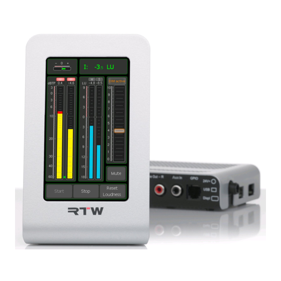
5.1 | Program Meter Signalpegel Loudness Beispiel: Program Meter des TM3-6CH mit kom- binierter Pegel- und Loudness-Anzeige Das Program Meter bietet eine vertikale oder horizontale Bargraph- Anzeige für die Einzelkanäle der aktiven Signalquelle. Das Instrument zeigt pro Kanal entweder den Signalpegel, die Loudness oder eine Kom- bination aus beiden an. Überprüfen Sie anhand des Program Meters, ob die Pegel und Loudness-Werte der Einzelkanäle den für das gemessene Audioprogramm gültigen Vorgaben entsprechen. Manual | TM3 5 | Instrumente | 5.1 | Program Meter DE-39... - Page 42 Die in den Werks-Presets in Gelb dargestellten Signalpegel können je nach Konfiguration des Presets nach zwei unterschiedlichen Verfahren angezeigt werden. Sie stehen für jeden Einzelkanal wahlweise als tradi- tionelle Quasi-Peakmeter (PPMs) mit verschiedenen wählbaren Skalen (DIN, British, Nordic etc.) oder aber mit der nach aktuellen Standards neu eingeführten True Peak-Skala zur Verfügung. Die True Peak-Messung soll sicherstellen, dass hoch ausgesteuertes Audiomaterial bei einer nachfol- genden Verarbeitung etwa in datenreduzierenden Codecs, in Abtastraten- wandlern (SRC) oder bei der D/A-Wandlung keine störenden Artefakte bilden kann. Beim Einsatz von Codecs gibt der EBU-Standard R128 einen Maximalpegel von –3 dBTP vor, ansonsten –1 dBTP. Die in den Werks-Presets in Cyan dargestellten Balken des Program Me- ter zeigen den Loudness-Momentanwert für jeden Einzelkanal mit einer Integrationszeit von 400 ms an. Werks-Presets mit Program Meter als Quasi-Peakmeter(PPM): • 2CH ANALOG PPM DIN • 2CH ANALOG PPM BRIIA Werks-Presets mit Program Meter als True Peak Meter (TP): • 2CH AES EBU TP LOUDNESS • 2CH AES ATSC TP LOUDNESS • 2CH SPDIF EBU TP LOUDNESS • 2CH SPDIF ATSC TP LOUDNESS Werks-Presets mit Program Meter in kombinierter True Peak/Loudness- Anzeige: • 5.1 AES EBU TP LOUDNESS • 5.1 AES ATSC TP LOUDNESS Manual | TM3 DE-40 5 | Instrumente | 5.1 | Program Meter...
-
Page 43: Loudness Sum
5.2 | Loudness Sum Skalenmarke Toleranz- für den bereich Target Level Momentary- Shortterm- Bargraph M Bargraph S Beispiel: Loudness Sum-Instrument im EBU-Modus zeigt Momentary-Bargraph M und Shortterm-Bargraph S. Der Integrated-Bargraph i ist ausgeblendet. Das Loudness Sum-Instrument gibt die aus allen Einzelkanälen eines Signals kombinierte Gesamt-Loudness mit bis zu drei Bargraphen an, die Messungen mit unterschiedlichen Zeitkonstanten repräsentieren. Bei Stereo-Quellen werden die Kanäle L und R für die Messung summiert, bei 5.1-Quellen die fünf Hauptkanäle (5.0). Manual | TM3 5 | Instrumente | 5.2 | Loudness Sum DE-41... - Page 44 Die drei im Loudness Sum-Instrument darstellbaren Bargraphen zeigen: • M (Momentary): Summierung der Momentary-Loudnessmessungen in den Einzelkanälen mit einer Integrationszeit von 400 • S (Shortterm): Summierte Loudness-Messung mit einer Integrati- onszeit von 3 s mit gleitendem Fenster. • i (Integrated): Gesamt-Loudness des Programms zwischen einem manuell gesetzten Anfangs- und Endpunkt. Zur Ausführung dieser Messung werden die Tasten Start, Stop und Reset genutzt. Nach Bedarf kann die Bargraph-Darstellung dieser drei Loudness-Mes- sungen individuell aktiviert und deaktiviert werden. Für die Loudness-Messung stehen zwei verschiedene Skalentypen zur Wahl: • Absolut-Skala in LKFS oder LuFS (abhängig vom eingestellten Loud- ness-Standard). • Relativ-Skala in Lu. Bei der relativen Skala entspricht der Wert 0 LU dem vom eingestellten Loudness-Standard vorgegebenen Integrated-Zielwert. Beim Standard EBU R128 sind das –23 LUFS, bei ATSC A/85 –24 LKFS. –23 LUFS sind mit –23 LKFS identisch. Um die Vorgaben des jeweiligen Loudness-Standards zu erfüllen, sollte das gemessene Programm auf den Zielwert dieses Standards ausgesteu- ert werden, also im Falle von EBU R128 auf 0 LU bei Verwendung einer Relativ-Skala und –23 LUFS bei Verwendung einer Absolut-Skala. Werks-Presets mit Loudness Sum-Instrument: • 2CH AES EBU SUM LOUDNESS • 2CH AES ATSC SUM LOUDNESS • 3 X 2CH EBU LOUDNESS...
-
Page 45: Lra
5.3 | LRa Skalenmarke für den Target Level LRA-Low-Range-Bereich Numerischer LRA-Wert Aktueller Integrated-Wert i LRA-Comfort-Zone-Bereich Integrated-Bargraph i LRA-High-Range-Bereich Beispiel: LRA-Instrument im „MagicLRA + I + Num“-Modus mit Integrated-Bargraph (I) und numerischer Anzeige Das LRA-Instrument bietet eine grafische Darstellung der Loudness Ran- ge (LRA). LRA ist ein statistisches Verfahren zur Messung der Loudness- Dynamik von Audioprogrammen. Je kleiner der gemessene LRA-Wert, desto geringer ist die Programm-Dynamik. Die Messung gibt also an, ob ein Programm eine durchgängig hohe Loudness aufweist (kleine LRA- Werte), oder ob große Unterschiede zwischen sehr leisen und sehr lauten Passagen vorkommen (hohe LRA-Werte). Manual | TM3 5 | Instrumente | 5.3 | LRA DE-43... - Page 46 Für LRA-Messungen existiert in den Loudness-Standards keine einheitli- che Zielgröße. Allerdings werden die drei farblich unterschiedlich markier- ten Bereiche „Comfort Zone“ (mittlere LRA-Werte), „High Range“ (hohe LRA-Werte) und „Low Range“ (niedrige LRA-Werte) unterschieden, in die ein Programm abhängig von seinem gemessenen LRA-Wert eingeordnet werden kann. Der im LRA-Instrument anwählbare Modus „MagicLRA“ nutzt eine Skala mit mittig fixierter Nullposition. Von dort aus dehnt sich der LRA-Bargraph symmetrisch mit einer zum LRA-Absolutwert korrespondierenden Länge aus. Der Modus „MagicLRA + I“ kombiniert die Loudness-Messungen LRA und Integrated (I) in einer gemeinsamen Darstellung. Der LRA- Bargraph hat dabei eine bewegliche, relative Nullposition, die mit dem gemessenen „Integrated“-Wert korrespondiert. Werks-Presets mit LRA-Instrument: • 2CH AES EBU TP LOUDNESS • 2CH AES ATSC TP LOUDNESS • 2CH AES EBU SUM LOUDNESS • 2CH AES ATSC SUM LOUDNESS • 2CH SPDIF EBU TP LOUDNESS • 2CH SPDIF ATSC TP LOUDNESS Manual | TM3 DE-44 5 | Instrumente | 5.3 | LRA...
-
Page 47: Loudness Num
5.4 | Loudness num Aktueller Integrated- Wert i Aktueller LRA-Wert Beispiel: Loudness Num-Instrument zeigt Integrated-Wert (i) und LRa-Wert. M-, S-, TPmax-, Mmax- und Smax-Wert sind ausgeblendet. Manual | TM3 5 | Instrumente | 5.4 | Loudness Num DE-45... - Page 48 Das Instrument Loudness Num bietet eine numerische Darstellung der folgenden Loudness-Messwerte: • M (Momentary): Summierung der Momentary-Loudnessmessungen in den Einzelkanälen mit einer Integrationszeit von 400 • S (Shortterm): Summierte Loudness-Messung mit einer Integrati- onszeit von 3 s mit gleitendem Fenster. • i (Integrated): Gesamt-Loudness des Programms zwischen einem manuell gesetzten Anfangs- und Endpunkt. Zur Ausführung dieser Messung werden die Tasten Start, Stop und Reset genutzt. • LRa: Loudness Range • TPmax: Maximal erreichter True-Peak-Wert in dBFS • Mmax: Maximal erreichter Momentary-Wert • Smax: Maximal erreichter Shortterm-Wert Nach Bedarf kann die numerische Darstellung dieser vier Loudness- Messungen individuell aktiviert und deaktiviert werden. Werks-Presets mit Loudness Num-Instrument: • 2CH AES EBU TP LOUDNESS • 2CH AES EBU SUM LOUDNESS • 3 X 2CH EBU LOUDNESS • 5.1 AES EBU TP LOUDNESS • 2CH SPDIF EBU TP LOUDNESS...
-
Page 49: Correlator
5.5 | correlator Negativer Positiver Bereich Bereich (rot) (grün) Beispiel: Korrelation ist zwischen +0,3 bis +0,7 (Vollauschlag bedeutet +1) Der Correlator zeigt die Phasenbeziehungen zwischen den beiden Ka- nälen eines Stereosignals und damit seine Mono-Kompatibilität an. Iden- tische Signale in beiden Kanälen haben die Korrelation +1, vollständig unabhängige Signale eine Korrelation von 0. Normale Stereomischungen zeigen meist Korrelationswerte zwischen 0,3 und 0,7 an. Wenn beide Ka- näle identische Signale führen, die Polarität in einem der beiden Kanäle aber vertauscht ist (180° Phase), beträgt die Korrelation –1. Achten Sie bei der Überprüfung von Audioprogrammen mit dem Cor- relator darauf, dass die Anzeige keine dauerhaft negativen Werte (rot) annimmt. Werks-Presets mit Correlator-Instrument: • 2CH ANALOG PPM DIN • 2CH ANALOG PPM BRIIA • 2CH SPDIF EBU TP LOUDNESS • 2CH SPDIF ATSC TP LOUDNESS Manual | TM3 5 | Instrumente | 5.5 | Correlator DE-47... -
Page 50: Firmware-Update
6 | Firmware-Update Um Ihren TouchMonitor TM3 stets auf dem neuesten Stand zu halten, sollten Sie in regelmäßigen Abständen die System-Software aktuali- sieren. Denn es stehen immer nur die Optionen und Lizenzen im Gerät zur Verfügung, die zum Zeitpunkt der Veröffentlichung der installierten Firmware-Version erhältlich waren. Firmware-Updates erhalten Sie im Mitglieder-Bereich der RTW-Webseite oder über Ihren Vertriebspartner. Das Firmware-Update ist denkbar einfach durchzuführen: Der TM3 wird wie ein USB-Laufwerk an den Computer angeschlossen und die Update-Datei direkt auf dem TM3 gespeichert. Nach ordnungsgemäßer Abmeldung vom Computer-System ist nur noch ein Neustart des TM3 erforderlich. In den folgenden Abschnitten ist das Update im Detail für die Betriebs- systeme Windows® und Mac OS X® beschrieben. Manual | TM3 DE-48 6 | Firmware-Update... - Page 51 Gehen Sie wie folgt vor, wenn Sie ein Firmware-Update durchführen: Schließen Sie den betriebsbereiten TM3 mittels eines handelsübli- chen USB-Interface-Kabels (A auf Mini-B) an den Computer an. Das Computer-System erkennt den TM3 als Laufwerk RTW-TM3. 2. Loggen Sie sich im Mitglieder-Bereich der RTW-Webseite (http:// www.rtw.de/sales-support/manuals-software.html) ein und gehen Sie unter Audio-Monitore auf die TouchMonitor TM3-Seite. 3. Benutzen Sie auf Ihrem Computer ein Windows®-Betriebssystem, folgen Sie den Schritten 4 bis 8. Benutzen Sie auf Ihrem Computer ein Mac OS X®-Betriebssystem, folgen Sie den Schritten 9 bis 13. Manual | TM3 6 | Firmware-Update DE-49...
-
Page 52: Windows
Windows® 4. Klicken Sie auf die Update-Datei (rtw-tm-fw-n-n.bin, n-n: Version). Das Dialog-Feld Dateidownload öffnet sich. 5. Klicken Sie auf die Schaltfläche Speichern. Manual | TM3 DE-50 6 | Firmware-Update | Windows®... - Page 53 6. Wählen Sie im Dialog-Feld Speichern unter im Kombinationsfeld Speichern in: das Laufwerk RTW-TM3 aus. 7. Klicken Sie auf die Schaltfläche Speichern. Die Firmware-Update- Datei wird jetzt auf den TM3 gespeichert. Manual | TM3 6 | Firmware-Update | Windows® DE-51...
-
Page 54: Mac Os X
8. Fahren Sie mit Schritt 14 fort. Mac OS X® 9. Zeigen Sie auf die Update-Datei (rtw-tm-fw-n-n.bin, n-n: Version), halten Sie die ctrl-Taste gedrückt und klicken Sie auf die Datei. Manual | TM3 DE-52 6 | Firmware-Update | Mac OS X®... - Page 55 10. Klicken Sie im angezeigten Menü auf Verknüpfte Datei laden un- ter ... Das Dialog-Feld Speichern unter öffnet sich. 11. Klicken Sie auf das Kombinationsfeld Ort und klicken Sie im ange- zeigten Menü auf die Option RTW-TM3. Manual | TM3 6 | Firmware-Update | Mac OS X® DE-53...
- Page 56 12. Wenn RTW-TM3 neben Ort angezeigt ist, klicken Sie auf Sichern. Die Firmware-Update-Datei wird jetzt auf den TM3 gespeichert. 13. Fahren Sie mit Schritt 14 fort. Manual | TM3 DE-54 6 | Firmware-Update | Mac OS X®...
- Page 57 14. Melden Sie nach erfolgtem Download den TM3 wie ein USB-Lauf- werk ordnungsgemäß vom Computer-System ab! Ziehen Sie erst dann das USB-Kabel vom Computer oder vom TM3 ab! ACHTUnG! - Die abmeldung vom Computer ist erforder- lich, um eine Beschädigung der kopierten Datei zu vermeiden! 15. Trennen Sie den TM3 von der Spannungsversorgung. 16. Schließen Sie nach ein paar Sekunden die Spannungsversorgung wieder an. 17. Der TM3 startet und führt jetzt automatisch das Update durch. Der Startvorgang kann daher etwas länger dauern als üblich. 18. Sobald der Bildschirm in den Normalbetrieb schaltet, ist das Update abgeschlossen und das Gerät betriebsbereit. HInWEIS - Wurde der Download auf den TM3 unterbrochen, die unvollständige Datei aus dem Laufwerk entfernt und in den Papierkorb des Betriebssystems gelegt, kann es bei Mac OS X® vorkommen, dass beim erneuten Aufspielen der Update-Datei eine Fehlermeldung wegen nicht genügendem Speicherplatz erscheint. Melden Sie in einem solchen Fall den TM3 ordnungsgemäß vom System ab, trennen Sie die USB-Verbindung und leeren Sie den Papierkorb. Danach sollte das Speichern der Update-Datei auf den TM3 wieder prob- lemlos funktionieren. Windows ist registriertes Warenzeichen oder Warenzeichen der Microsoft Corporation in den Vereinigten Staaten und/oder anderen Ländern.
-
Page 58: Technische Daten
7 | Technische Daten System allgemein Spannungsversorgung: +24 V DC (externe Überstrombegrenzung auf 2 A erfor- derlich!) Stromaufnahme: 160 mA Nennstrom, Einschaltstrom deutlich höher Display: 4,3’’-TFT Touch-Screen 272 x 480 Pixel Anschlüsse: 1 x 4-pol. Kleinspannungsstecker Typ 710 (DC) 1 x USB Mini-B; USB 2.0 Full Speed-Anschluss zum Datenaustausch zwischen Device-Configurator-Software Devicer DC1 auf dem Computer und TM3 1 x GPIO (RJ-11-6P6C) für definierte Funktionen oder Preset-Aufruf 2 x RCA-F (unsym., analog) 2 x RCA-F (unsym., S/PDIF in/out) 1 x 25-pol. Sub-D-F (sym., analog alternativ, bis zu 3 x AES3 in/out) Abmessungen (B x H x T): Display-Einheit: 82,5 x 138 x 50 mm Interface-Box: 146 x 29 x 85 mm Gewicht (ohne Netzteil): Display-Einheit ca. 320 g, Interface-Box ca. 460 g Arbeitstemperaturbereich: + 5° bis +40° C Funktionen • Instrumente frei skalierbar und positionierbar • Peakmeter bis 6-Kanal • Loudness-Meter: ITU-R BS.1770-2/1771, EBU R128, ATSC A/85, ARIB, anwenderspezifisch • Loudness-Range-Instrument (LRA) • SPL-Meter • Stereo-Korrelator • Dialnorm-Messung (ohne speech intelligence) - Page 59 Technische Daten (Fortsetzung) Analoge Eingänge 2 analoge Eingänge, 2 x RCA oder alternativ über Sub-D-F- Einbaubuchse, 25-polig • RCA - Eingangsempfind- lichkeit für 0-dB- Anzeige RCA: mit Potis einstellbar von 150 mV bis 30 V - Impedanz: > 10 kΩ • Sub-D - Eingangsempfind- lichkeit für 0-dB- Anzeige Sub-D: +6 dBu (1,55 V) - Referenzpegel: mit Software einstellbar von 0 dBu bis +10 dBu - Max. Eingangspegel: +24 dBu - Impedanz: > 10 kΩ, elektronisch symmetrisch Digitale Ein-/Ausgänge 1 digitaler S/PDIF-Eingang, RCA, 75 Ω 1 digitaler S/PDIF-Ausgang, RCA • TM3: 1 AES3-Eingang, symmetrisch, 110 Ω, Sub-D-F-Einbaubuchse, 25-polig (Ein- und Ausgang)
- Page 60 Technische Daten (Fortsetzung) analoge Peakmeter Analoge Skalen: • DIN5: +5 .. -50 dB, • Nordic: +12 .. -42 dB, • BR IIa: 7 .. 1 (British), • BR IIb: +12 .. -12 dB (British), • Zoom10: +10 .. –10, • Zoom1: +1 .. –1, • SMPTE24: +24 .. –30 • SMPTE20: +20 .. –40 • NHK Integrationszeit: entsprechend Standard oder 20 ms, 10 ms, 1 ms, 0,1 ms Peakhold-Anzeige: 1 s, 2 s, 4 s, 10 s, 20 s, 30 s, manueller Reset oder aus Digitale Peakmeter Wortbreite: 24 Bit Digitale Skalen: • TP60: +3 .. –60 dB • TP20: +3 .. –20 dB • Dig60: 0 .. –60 dB • Dig20: 0 .. –20 dB • Dig0: +18 .. 0 dB • Dig18: +18 .. –18 dB • Dig40: +20 .. –40 dB...
- Page 61 Technische Daten (Fortsetzung) Hochpassfilter: Off, 5 Hz, 10 Hz, 20 Hz Peakhold-Anzeige: 1 s, 2 s, 4 s, 10 s, 20 s, 30 s, manueller Reset oder aus Over-Anzeige-Dauer: 1 s oder manuell Over-Anzeige PPM - Ansprechschwelle: Full Scale, Full Scale -1LSB, Full Scale -2LSB, –0.1 dBFS, –0.5 dBFS, –1 dBFS, –2 dBFS, –3 dBFS - Ansprechzeit: 1 bis 15 Samples - Wortbreite: 16 bis 24 Bit, einstellbar Over-Anzeige True Peak - Ansprechschwelle: einstellbar AES3-Status-Monitor Anzeige: • Kanal-Daten in Klartext-, Hexadezimal- oder Binär- Darstellung • Kanal einstellbar • Audio-Bit-Aktivität • Hardware-Status Global Keyboard Globales Tastenfeld zur Steuerung definierter Funktionen in verschiedenen Instrumenten und zum Preset-Aufruf, ermöglicht auch die externe Steuerung über die GP IO-...
- Page 62 Technische Daten (Fortsetzung) Anwenderspezifischer Loudness-Modus Anzeige: • Bargraphen für jeden Einzelkanal (kombinierbar mit PPM-Bargraphen) • M-Bargraph (Momentary: momentaner Wert • S-Bargraph (Short: Kurzzeit-Wert) • I-Bargraph (Integrated: Langzeit-Wert) Numerische Anzeige: S-, I-, M-, LRA-, TPmax-, Mmax-, Smax-Wert Skalen: *) Loudness-Skalen: • EBU+9: +9 .. –18 LU • EBU+18: +18 .. –36 LU • EBU+9a: 14 .. –41 LUFS • EBU+18a: –5 .. –59 LUFS • EBU0: 0 .. –60 LUFS • ITU+9: +9 .. –18 LU • ITU0: 0 .. –30 LKFS • ATSC0: 0 .. –60 LKFS • ATSC0a: 0 .. –30 LKFS Bewertungsfilter: K-Filter entsprechend ITU-R BS.1770 Zielwert (Target Level): *) –23 LUFS; einstellbar von –10 bis –30 LUFS/LKFS Time & Gate Momentary: *) - Fensterzeit: einstellbar von 200 ms bis 1000 ms in 100-ms-Schritten - Integrationszeit:...
- Page 63 Technische Daten (Fortsetzung) Loudness Range instrument (LRa) Anzeige: Grafische Darstellung der Loudness Range Modus: wählbar: LRA Bar, MagicLRA, MagicLRA + I, MagicLRA + I + Num Skalenbereich: wählbar: 6 LU, 10 LU, 20 LU, 30 LU Minimalbereich: 2 LU; einstellbar von 1 bis 20 LU in 1-LU-Schritten Komfortbereich: 4 LU; einstellbar von 1 bis 20 LU in 1-LU-Schritten Maximalbereich: abhängig vom gewählten Skalenbereich und des Umfangs des Komfortbereichs Farben: für jeden Bereich individuell wählbar SPL-Meter-Modus Anzeige: • Bargraphen für jeden Einzelkanal (kombinierbar mit PPM-Bargraphen) • Bargraph für Summe der Kanäle Referenzpunkt: einstellbar von 68 dB bis 88 dB in 1-dB-Schritten Bewertung: Linear, A (Leq(A)), C, CCIR (Leq(M)), K Integrationszeit: Fast (125 ms), Slow (1 s) TM3-SW6UPG Software-Lizenz zur Erweiterung der 2-Kanal-Stereo-Version auf 6-Kanal-Betrieb (2-Kanal-Stereo, 1- bis 6-Kanal, 5.1). Nach Einreichung der im Gerät erzeugten Anforderungsdatei und Übertragung der zurückerhaltenen Lizenzdatei ins Gerät erfolgt die Aktivierung.
- Page 64 Technische Daten (Fortsetzung) Lieferumfang TouchMonitor TM3 : • 2-Kanal-Stereo-Version • TM3-Display-Einheit mit 4,3“-Touch-Screen im Tisch- gehäuse mit angeschlagenem Verbindungskabel (2 m) • damit verbundene Interface-Box • Netzteil, Manual Bestellnr.: TM3 TouchMonitor TM3-6CH : • 6-Kanal-Version (2-Kanal-Stereo, Mehrkanal, 5.1) • TM3-Display-Einheit mit 4,3“-Touch-Screen im Tisch- gehäuse mit angeschlagenem Verbindungskabel (2 m) • damit verbundene Interface-Box • Netzteil, Manual Bestellnr.: TM3-6CH Optionale Software-Lizenz • Software-Lizenz TM3-SW6UPG zur nachträglichen Erweiterung der TM3-Geräte auf den Funktionsumfang der TM3-6CH-Geräte Optionales Zubehör • Weitspannungsnetzteil 1168-R (100 - 240 V AC/ 24 V DC 2,7 A, Tischgerät mit passendem Netzkabel für verschiedene Stromnetze) • Adapterkabel 1162 Auflösungsadapter (2 m) für TM3-Interface-Box von 25-pol. Sub-D-M-Stecker auf 2 x XLR-F-Kupplungen (analoge Eingänge), 3 x XLR-F-Kupplungen (AES3- Eingänge) und 3 x XLR-M-Stecker (AES3-Ausgänge) • Verlängerungskabel 1161 für TM3-Interface-Box, 10 m,...
-
Page 65: Ce-Konformität
8 | CE-Konformität EG-Konformitätserklärung | Richtlinie 2004/108/EG und Richtlinie 2006/95/EG Wir, die RTW GmbH & Co.KG, Elbeallee 19, 50765 Köln, Deutschland, erklären in alleiniger Verantwortung, dass das Produkt: RTW TouchMonitor TM3 Serie (Tischgeräte, bestehend aus Display-Einheit und Interface-Box, inklusive Verbin- dungskabel und Netzteil) auf das sich diese Erklärung bezieht, mit den folgenden Normen bzw. normativen Dokumenten übereinstimmt: EMV 2004/108/EG EN 61000-6-3: 2007-10-01 Emissions: EN 55022: 2007-06-01 Class B, gestrahlt EN 55022: 2007-06-01 Class B, leitungsgeführt EN 61000-6-1: 2007-12-01 Immunity: EN 61000-4-2 + A1 + A2: 2002-02-01 EN 61000-4-3: 2007-11-01 EN 61000-4-4: 2005-09-01 EN 61000-4-5: 2007-08-01 EN 61000-4-6 + A1: 2002-02-01 EN 61000-4-11: 2005-04-01 Sicherheit 2006/95/EG EN 60950-1: 2007-01-01 Geprüft und dokumentiert von nachfolgend aufgeführten Firmen: SERCO GmbH, Bonn, akkreditiertes EMV-Prüflabor RTW GmbH & Co.KG, Köln Datum und Unterschrift des Verantwortlichen: 2012-03-06 i. A. Manual | TM3 8 | CE-Konformität DE-63... -
Page 66: Lizenzen
9 | Lizenzen Lizenzen der implementierten Software Die Produkte der TouchMonitor TM3 Serie umfassen neben der Hardware ein Soft- warepaket, das Programme mit unterschiedlichen Lizenzen beinhaltet: A. Software aus der Urheberschaft der RTW GmbH & Co.KG, die nur zum bestim- mungsmäßen Gebrauch des Gerätes verwendet werden darf (Applikation, DSP- Programme, Bootloader). Diese Software ist Eigentum der RTW GmbH & Co.KG und unterliegt dem deutschen und dem internationalen Urheberrecht. B. Open Source Software, die unter der GPL (General Public License) der Free Software Foundation (FSF) steht: 1. Linux Kernel 2. TinyLogin 3. Busy Box 4. MTDTools 5. GDBServer Die GPL finden Sie unter http://www.gnu.org/licenses/gpl.html. Rechtsverbindlich ist die englische Originalfassung. C. Software, die unter der LGPL (Lesser General Public License) der Free Software Foundation (FSF) steht: Qt®-Bibliothek von Nokia Corporation Die LGPL finden Sie unter http://www.gnu.org/licences/lgpl-2.1.html. Qt® ist ein eingetragenes Warenzeichen (Marke) der Nokia Corporation, Finland. Manual | TM3 DE-64 9 | Lizenzen... - Page 67 D. Software, die unter der Lizenz des OpenSSL Project steht: „This product includes software developed by the OpenSSL Project for use in the OpenSSL Toolkit. (http://www.openssl.org/)“ Die Lizenz finden Sie unter http://www.openssl.org/source/license.html. An der unter B. aufgeführten Software wurden teilweise Änderungen vorgenom- men. In diesem Fall können Sie die Sourcen der geänderten Software von RTW auf Anfrage innerhalb von drei Jahren nach Erhalt des Gerätes zugesandt bekommen. Köln, April 2012 Lizenzen der beim Start angezeigten Bilder Der Startbildschirm des TouchMonitor enthält bearbeitete Bilder, die auf der Fotografie „Cologne_CathedralNight-6.jpg“ von Lukasz Kryger, Edingburgh, Scotland, basieren. Die Bilder stehen unter der Creative Commons Attribution 2.0 Generic License (http://commons.wikimedia.org/wiki/File:Cologne_CathedralNight-6.jpg, http://creativecommons.org/licenses/by/2.0/deed.de). Warenzeichen Windows ist registriertes Warenzeichen oder Warenzeichen der Microsoft Corporati- on in den Vereinigten Staaten und/oder anderen Ländern. Mac OS X ist Warenzeichen der Apple Inc., registriert in den Vereinigten Staaten und anderen Ländern. Manual | TM3 9 | Lizenzen DE-65...
-
Page 68: Blockdiagramm
Blockdiagramm © 05/2012 | Technische Änderungen vorbehalten. RTW GmbH & Co. KG Am Wassermann 25 | 50829 Köln | Germany Phone: +49 221. 70 913-0 | Fax: +49 221. 70 913-32 Internet: www.rtw.de | E-Mail: rtw@rtw.de... - Page 69 TouchMonitor TM3 Operating Manual...
- Page 70 Operating Manual RTW TouchMonitor TM3 Series • TM3 • TM3-SOLO • TM3-6CH Manual version: Issued: May 25 , 2012 Software version: 1.42 and higher | May 24th, 2012 © 2012 | Technical changes without prior notice! RTW GmbH & Co.KG | Am Wassermann 25 | 50829 Köln | Germany Fon +49 221. 70 913-0 | Fax +49 221. 70 913-32 www.rtw.de | rtw@rtw.de WEEE Reg.-no.: DE 90666819 Category: Device type: These instruments comply with and fall under category 9 Mo n itoring and control equipment of Annex 1B of the RoHS-Directive 2002/95/EC. notes: • The information contained in this manual was correct at the time of printing, however due to our policy of continuous improvement, actual product displays may differ slightly from those shown here. • The current manual, available firmware updates, and Devicer DC1 for...
- Page 71 Safety Instructions The following symbols may be marked on the panels or covers of equip- ment or module and are used in this manuals with these terms: WaRning! This symbol alerts you to a potentially hazardous condition, such as the presence of dangerous voltage that could pose a risk of electrical shock. Refer to the accompanying Warning Label or Tag, and exercise extreme caution. aTTenTiOn! This symbol alerts you to important operating considerations or a po- tential operating condition that could damage equipment. If you see this marked on equipment, consult the operating manual for precautionary instructions. nOTe This symbol points your attention to specific characteristics that are no malfunctions. Manual | TM3 Safety Instructions EN-3...
- Page 72 • Keep these instructions. Keep all safety and operating instructions for future reference! • Heed all warnings on the unit and in the safety and operating instruc- tions before you install and operate the unit! • Follow all instructions to ensure against injury to yourself and damage to the unit or other objects connected to the unit. To prevent possible electrical shock, death, fire, injuries and mal- functions, use this product only as specified. Only use attachments and accessories specified by the manufacturer. The units of the TouchMonitor series are designed for indoor use only and may only be operated with a power supply unit provided for it. WaRning! Always follow the safety precautions below to avoid the possibility of se- rious injury or even death from electrical shock, short-circuiting, damages, fire, or other hazards. These precautions include, but are not limited to, the following: • Do not open the housing. Inside, there are no user-serviceable parts. Any necessary servicing shall be performed by a properly qualified technician. • Do not attempt to repair any part of the unit. Repairs shall only be car- ried out by qualified personnel. • Never remove any parts from the unit and do not make any modifica- tions to the unit without the express written consent of RTW. Modifi- cations can cause both safety hazards and affect the unit’ s EMI-CE conformity. Manual | TM3 EN-4 Safety Instructions...
- Page 73 • Only use the power cord and power supply specified for this product and certified for the country of use. • Use with power supply model STD-2427PA, manufactured by Adapter Technology Co Ltd. (RTW 1168-R). • The power cord of the external power supply disconnects the product from the power source. Do not block the power cord or power supply; it must remain accessible to the user at any time. • Connect and disconnect properly. Use only connectors specified for this product and fix them tight before use. • Observe all terminal ratings and markings on the product. Consult the operating manual for further ratings information before making con- nections to this product. • Do not apply a potential to any terminal that exceeds the maximum rating of that terminal. • Avoid exposed circuitry. Do not touch exposed connections and com- ponents when power is present. • Turn off and disconnect the power supply immediately it the unit pro- duces unusual smells, noises or smoke, or if foreign substances (e. g. liquids) or foreign objects enter the unit. • Because of the installed battery the unit shall not be exposed to exces- sive heat such as sunshine, fire, or similar. • Caution: Danger of explosion if battery is incorrectly replaced. Replace only with the same or equivalent type. • Do not cover the unit and do not place any objects or anything contai- ning liquids on it.
- Page 74 aTTenTiOn! Always follow the safety precautions below to avoid the possibility of phy- sical injury to you or others, or damage to the unit or other property. These precautions include, but are not limited to, the following: • Do not block any ventilation openings. Install in accordance with the manufacturer‘s instructions to prevent the internal temperature from becoming too high. • Do not install near any heat sources such as radiators, heat registers, stoves, or other apparatus (including amplifiers) that produce heat. • Also keep away the unit from direct incident solar radiation. • Keep product surfaces clean and dry. Clean only with dry cloth. • Never use any solvent based liquids for cleaning the housing surfaces and the display. • Do not place the unit in an unstable position where it might accidently fall over. • Before connecting any devices to the unit make sure that the power supply is disconnected. • Protect the power cord from being walked on or pinched particularly at plugs, convenience receptacles, and the point where they exit from the apparatus. • Unplug this apparatus during lightning storms or when unused for long periods of time. • Before moving the unit, remove all connected cables. • When transporting or moving the unit, always take care not to scratch or damage the housing surfaces and the display. • Refer all servicing to qualified service personnel. Servicing is required when the apparatus has been damaged in any way, such as power- supply cord or plug is damaged, liquid has been spilled or objects have fallen into the apparatus, the apparatus has been exposed to rain or...
- Page 75 Information on installed battery The pcb features a battery socket with a 3 V Li/Mn coin cell battery, type CR 1225. It must be inserted from the side with its positive pole on top and its negative pole towards the pcb surface. Environmental Considerations Observe the following information about the environmental impact of the product and the following guidelines when recycling an instrument or component (product end-of-life handling): • Equipment Recycling Production of this equipment required the extraction and use of natural resources. The equipment may contain substances that could be harm- ful to the environment or human health if improperly handled at the product’ s end of life. In order to avoid release of such substances into the environ m ent and to reduce the use of natural resources, we en- courage you to recycle this product in an appropriate system that will ensure that most of the materials are reused or recycled appropriately. • Battery Recycling This product contains a lithium manganese dioxide (Li/Mn) battery, which must be recycled or disposed of properly according to your local government regulations. • Restriction of Hazardous Substances This product has been classified as Monitoring and Control equipment, and is outside the scope of the 2002/95/EC RoHS Directive. This product may contain lead, cadmium and/or mercury in slight quantities. Please dispose of or recycle the electronic parts or devices according to your local government regulations. Manual | TM3 Safety Instructions EN-7...
- Page 76 Content Safety Instructions 3 Important Safety Instructions 4 Warning! Attention! 6 Environmental Considerations 7 content 1 | Before You Begin 1.1 | Design Concept 9 1.2 | Scope of Delivery 12 1.3 | Options 12 2 | installation 2.1 | Connection 14 2.2 | Pin Assignment 16 3 | Operation 19 3.1 | System Start-up 19 3.2 | Signal Sources and Synchronization 20 3.3 | Loading vertical and horizontal Presets 22 4 | Presets 5 | instruments 5.1 | Program Meter 39 5.2 | Loudness Sum 41 5.3 | LRA 43 5.4 | Loudness Num 45 5.5 | Correlator 47 6 | Firmware Update 48 Windows® Mac OS X® 52 7 | Specifications 56 8 | EC Conformity 63 9 | Licenses Block Diagram Manual | TM3...
-
Page 77: Before You Begin 1.1 | Design Concept
1 | Before You Begin 1.1 | Design Concept Thank you for purchasing the TouchMonitor TM3 made by RTW. You have settled for a highly efficient metering solution based on modern hardware and most recent technology that combines intuitive, easy operation with a high degree of flexibility and configuration options for professional use. Manual | TM3 1 | Before You Begin | 1.1 | Design Concept EN-9... - Page 78 Being a stand-alone unit using an elegant touchscreen-based preset control, the TouchMonitor TM3 will always provide you with the exact audio signal information that you will need for fast and safe interpretation even without having a profound technical background. The high-contrast 4.3“ screen can be used vertically or horizontally alternatively. It will assist you delivering a conclusive visual processing of technical parameters at all times. The TM3‘s interface box allocates all relevant audio input inter- faces. While the Stereo version can handle up to two channels of analog or digital signals at a time, the TM3-6CH supports six-channel digital signal processing as well (retrofitable for Stereo units). Manual | TM3 EN-10 1 | Before You Begin | 1.1 | Design Concept...
- Page 79 When it comes to configuring local presets using the Devicer DC1 soft- ware application (Windows® and Mac OS X® compatible), the TM3‘s po- wer and flexibility really shines. Besides PPM and True Peak instruments, the TM3 features comprehensive loudness measuring options conforming to all relevant international standards (EBU R128, ITU-R BS.1770-2/1771, ATSC A/85, and ARIB). Loudness instruments include single-channel and summing bargraphs, loudness range and numerical displays. Manual | TM3 1 | Before You Begin | 1.1 | Design Concept EN-11...
-
Page 80: Scope Of Delivery
1.2 | Scope of Delivery Unpack the instrument, find your version below, and check, if you received all items listed. If components are missing, please contact your dealer. TouchMonitor TM3 Series TM3 (Stereo) connected Display Unit + Interfacebox Power Supply Manual TM3-6CH (6-channel) connected Display Unit + Interfacebox Power Supply Manual 1.3 | Options TM3-SW6UPG 6-channel upgrade for TM3 1.4 | accessories Extension 1161 Snake cable 1162... - Page 81 2 | Installation The TouchMonitor TM3 units are designed for free positioning on tables, desks, et. al. A TM3 unit consist of a display unit with 4.3 inch touch screen and a separate interfacebox featuring many capabilities of connecting. The connected cable supplies the display unit with power and data. Power supply for the whole unit is supplied through the +24 V DC con- nector on the interfacebox. Use with power supply model STD-2427PA, manufactured by Adapter Technology Co Ltd. (which is the external power supply unit RTW 1168-R wide voltage power supply, included in TM3 and TM3-6CH packages). aTTenTiOn! – Please read before installing: • Before installing the unit please study the safety instructions and the information on connection and pin assignment. • An external overcurrent protective device (2 A max.) shall be installed when using an external 24 V DC power supply! • Make sure that the delivered power supply unit is not connected. • Place the unit at a suited place. The display unit shall positioned secu- rely on a flat surface. The interface box may be placed corresponding to the cable length away outside the sight field, e. g. on the bottom behind a table. Please take care about a good guiding of the connected cable. • Connect unbalanced signal sources to the RCA connectors. Connect balanced signal sources to the Sub-D connector. Connect all your other components to the appropriate connectors. Use the correct stan- dard connection cables for the components and take care about the pin assignment described in paragraph 2.2! • Finally, connect the locking 4-pin low voltage connector of the external power supply to the +24 V DC connector of the interface box. Con- nect the external power supply to mains. • The TouchMonitor will initiate its system startup sequence. After the boot-up the unit is ready for use.
-
Page 82: Installation 2.1 | Connection
2.1 | connection Front View of the Interface Box Potentiometers for adjustment of the input sensitivity of 0 dB reading GP IO (RJ-11-6P6C) (150 mV - 30 V) S/PDIF Out (RCA) Analog In L (RCA) *) S/PDIF In Analog In R (RCA) (RCA) *) *) analog in via RCA and analog in via Sub-D can- not be used in parallel! Manual | TM3 EN-14 2 | Installation | 2.1 | Connection... - Page 83 connection (continued) Left Side View of the Interface Box Analog In L/R (Sub-D) *) 3 AES3 In/Out (1 - 3, Sub-D) *) analog in via RCA and analog in via Sub-D cannot be used in parallel! TM3: Only 1 AES3 In/Out for each preset selectable TM3-6CH: 3 AES3 In/Out for each preset selectable Right Side View of the Interface Box Connected to display unit (2 m, max. 15 m) USB 2.0 Mini-B (USB interface cable for the exchange of Devicer DC1 and TM3 data required) 4-pin locking low voltage connector 24 V DC, 160 mA (nominal), for connecting the wide voltage power supply Manual | TM3 2 | Installation | 2.1 | Connection EN-15...
-
Page 84: Pin Assignment
Digital In, Digital Out (S/PDIF, unbalanced, RCA-F) Pin: Function: Pin: Signal Ring Shield/chassis Ring: (External view of the connector) nOte - The S/PDIF input is permanently terminated with 75 Ω. USB-Mini-B Full Speed USB 2.0 interface for connecting the TM3 unit to the compu- ter using a standard USB data cable. The USB interface is used for the data exchange between Device Configurator software Devicer DC1 and TouchMonitor TM3. Manual | TM3 EN-16 2 | Installation | 2.2 | Pin Assignment... - Page 85 Pin assignment (continued) sub-D Connector (25-pin Sub-D-F) Pin: Function: Analog input R (+, hot) � � � � � � � � � � � Analog input R (–, cold) pair 8 � � � � � � � � � � � Shield/chassis � � � � � � � � � � � �...
- Page 86 Pin assignment (continued) gPiO (RJ-11-6P6C socket) External control of functions and presets recall as defined in the Global Keyboard menu. The inputs defined as „active low“ have to be switched against 0 V (Pin 1). Pin: Function: 2 - 6 Function acc. to definition in the menu (External view of the connector) 24 V DC (4-pin locking low voltage, type Binder 710) Pin: Function: +24 V DC Pin 3 Pin 2 +24 V DC Pin 4 Pin 1 0 V (External view of the connector) nOTE - An external overcurrent protective device (2 A max.) shall be installed when using an external 24 V DC power supply! Manual | TM3 EN-18 2 | Installation | 2.2 | Pin Assignment...
-
Page 87: Operation
3 | Operation 3.1 | System Start-up Please ensure that the display unit is connected to the interface box by means of the supplied cable (delivery status). • Connect an analog or digital signal source to the interface box. Please refer to the corresponding notes in the 2 | installation chapter as well as in the 3.2 | Signal Sources section (see below). • Connect the specified power supply to the interface box. Use the mains adaptor RTW 1168-R supplied with some of the TM3 versions or available as an accessory. • Connect the power supply to the mains supply. After a short boot-up sequence, the TouchMonitor TM3 will be ready for use. Manual | TM3 3 | Operation | 3.1 | System Start-up EN-19... -
Page 88: Signal Sources And Synchronization
3.2 | Signal Sources and Synchronization The TouchMonitor TM3 features several inputs for analog and digital signal sources. These are described in the 2 | installation chapter in full detail. Selecting the active signal input for the current measurement is done by selecting an appropriate preset. In this way, switching between several sources connected to the unit is done very easily by simply loa- ding presets. For the TM3‘s factory presets stored in the unit by default, all input assignments are described in the 4 | Presets chapter. If, on the other hand, your unit holds individual presets that were created by a system admin, the administrator will provide you with the appropriate input assignment information. Also, the preset names could be used to designate the input connector used by a preset. Digital Inputs - TouchMonitor TM3 and TM3-SOLO The 2-channel versions of the TM3 have a S/PDIF input (RCA) and 3 times 2-channel inputs in AES3 format that are accessible through the 25-pin Sub-B connector. These digital inputs cannot be used in parallel in the same preset - only one of them is available at the same time. How- ever, multiple signal sources can still be connected in parallel and can be accessed sequentially by switching presets. Manual | TM3 EN-20 3... - Page 89 Digital Inputs - TouchMonitor TM3-6CH The 6-channel version of the TM3 has a S/PDIF input (RCA) and 3 times 2-channel inputs in AES3 format that are accessible through the 25-pin Sub-D connector. The 3 digital inputs in AES3 format can all be used in the same preset so that up to six audio channels can be measured in parallel. However, it is not possible to combine an AES3 input with the S/PDIF and/or analog input(s) in the same preset. Synchronization of Digital Signal Sources On its four digital signal inputs (RCA and 25-pin Sub-D connector), the TM3 handles digital signal sources with sampling rates up to 96 kHz. If using digital sources in AES3 format, a digital signal must always be present for synchronization purposes at the first AES3 input - even if the active preset actually measures one of the other AES3 inputs. If using the S/PDIF input (RCA), the TM3 will sync to this input. If using the analog input and a valid digital signal is present at the first AES3 input, this di- gital signal will be used for sync. Otherwise, the TM3 will use its internal clock to be the sync reference. Manual | TM3 3 | Operation | 3.2 | Signal Sources and Synchronization EN-21...
-
Page 90: Loading Vertical And Horizontal Presets
3.3 | Loading vertical and horizontal Presets The TM3‘s display can be used in vertical as well as horizontal display mo- des. For both orientations, suitable preset versions are stored in the unit. Vertical display mode In order to use the TM3 in vertical display mode, just place the display unit in its upright position. Wipe across the touchscreen with your finger in horizontal direction to browse through the available presets for vertical display mode. Each preset will be presented with its name and a preview illustration of the instruments and display layout used. Touch the white circled arrow button in the center to load a preset. To select any other preset, just wipe again. Manual | TM3 EN-22 3 | Operation | 3.3 | Loading vertical and horizontal Presets... - Page 91 Horizontal display mode In order to use the TM3 in horizontal display mode, rotate the display unit to the left so that the base is positioned on the right hand side. Wipe across the touchscreen with your finger in horizontal direction to switch the unit to horizontal display mode and to browse through the available presets in that mode. Each preset will be presented with its na- me and a preview illustration of the instruments and display layout used. Touch the white circled arrow button in the center to load a preset. To select any other preset, just wipe again. In order to switch the TM3 back to vertical display mode, just place the display unit in its upright position again and wipe across the touchscreen in either horizontal direction to browse through the available presets. nOTE - Please note that the TM3 recognizes the wipe orientation (lengthwise or crosswise) in order to switch between vertical and horizon- tal display modes. It doesn‘t use a motion sensor for this. Manual | TM3 3 | Operation | 3.3 | Loading vertical and horizontal Presets EN-23...
-
Page 92: Presets
4 | Presets At time of delivery, the TouchMonitor TM3 contains factory presets pre- senting a cross-section of the applications, audio connections and stan- dards supported by the unit. Using these presets, you can start working with the TM3 right out of the box, even without connecting it to a compu- ter and installing the configuration software Devicer DC1 first. All presets are available in two versions for vertical as well as horizontal use. Please refer to chapter 3 | Operation for details about loading pre- sets and switching between vertical and horizontal display modes. nOTE - Please note that editing the factory presets or creating your own individual presets is only possible using the RTW Devicer DC1 configuration software (Windows® and Mac OS X® compatible). This software is available for download free of charge under Audio Monitors/ TouchMonitor TM3 in the member area of the RTW homepage (http:// www.rtw.de/en/sales-support/manuals-software.html). Use of the De- vicer DC1 software is explained in a separate manual that also can be found on this web site. The Devicer DC1 software is also used for upgrading the unit to the 6-channel mode (TM3-SW6UPG license). Manual | TM3 EN-24 4 | Presets... - Page 93 The following listing describes the most important features of all factory presets. The input connectors used by each preset are also listed. The audio inputs of the TM3 and the pinouts of the Sub-D connector are de- scribed in detail in chapter 2 | installation. nOTE - Presets with the input notation analog are calibrated to the indicated reference level (+6 dBu) only if using the balanced analog inputs on the Sub-D connector. If you prefer to use the unbalanced RCA inputs instead, please make sure that these inputs are calibrated to your preferred reference level before using them. The unbalanced reference level can be set using the two unbal Ref potentiometers close to the RCA inputs over the range of 150 mV - 30 V. As a factory default, the RCA inputs are calibrated to a reference level of –10 dBV if a reference level of +6 dBu for the balanced inputs is set in the preset. The chapter 5 | instruments contains short descriptions of the inst- ruments used in the presets as well as some hints for a fast interpre- tation of the readings. Manual | TM3 4 | Presets EN-25...
- Page 94 2cH anaLOg PPM Din Input: Analog L, Analog R Reference Level: +6 dBu for “0 dB” (analog input reference +6 dBu) Program Meter Scale: DIN5 Instruments: Program Meter, Correlator Manual | TM3 EN-26 4 | Presets...
- Page 95 2cH anaLOg PPM BRiia Input: Analog L, Analog R Reference Level: +8 dBu for “6” (analog input reference +6 dBu) Program Meter Scale: BritishIIa Instruments: Program Meter, Correlator Manual | TM3 4 | Presets EN-27...
- Page 96 2cH aeS eBu TP LOuDneSS Input: AES3 1 Program Meter Scale: TP60 Loudness Standard: EBU R128 Instruments: Program Meter, LRA, Loudness Num Keys: Loudness Start, Stop, Reset Manual | TM3 EN-28 4 | Presets...
- Page 97 2cH aeS eBu SuM LOuDneSS Input: AES3 1 Loudness Standard: EBU R128 Instruments: Loudness Sum, LRA, Loudness Num Keys: Loudness Start, Stop, Reset Manual | TM3 4 | Presets EN-29...
- Page 98 3 X 2cH eBu LOuDneSS (only available with TM3-6CH) Input: AES3 1, AES3 2, AES3 3 Loudness Standard: EBU R128 Instruments: 3 x Loudness Sum, 3 x Loudness Num Keys: Loudness Start, Stop, Reset (for each channel pair) Manual | TM3 EN-30 4 | Presets...
- Page 99 5.1 aeS eBu TP LOuDneSS (only available with TM3-6CH) Input: AES3 1, AES3 2, AES3 3 Program Meter Scale: TP60 Loudness Standard: EBU R128 Instruments: Program Meter, Loudness Num Keys: Loudness Start, Stop, Reset Manual | TM3 4 | Presets EN-31...
- Page 100 2cH SPDiF eBu TP LOuDneSS Input: S/PDIF Program Meter Scale: TP60 Loudness Standard: EBU R128 Instruments: Program Meter, Correlator, LRA, Loudness Sum, Loudness Num Keys: Loudness Start, Stop, Reset Manual | TM3 EN-32 4 | Presets...
- Page 101 2cH aeS aTSc TP LOuDneSS Input: AES3 1 Program Meter Scale: TP60 Loudness Standard: ATSC A/85 Instruments: Program Meter, LRA, Loudness Num Keys: Loudness Start, Stop, Reset Manual | TM3 4 | Presets EN-33...
- Page 102 2cH aeS aTSc SuM LOuDneSS Input: AES3 1 Loudness Standard: ATSC A/85 Instruments: Loudness Sum, LRA, Loudness Num Keys: Loudness Start, Stop, Reset Manual | TM3 EN-34 4 | Presets...
- Page 103 3 X 2cH aTSc LOuDneSS (only available with TM3-6CH) Input: AES3 1, AES3 2, AES3 3 Loudness Standard: ATSC A/85 Instruments: 3 x Loudness Sum, 3 x Loudness Num Keys: Loudness Start, Stop, Reset (for each channel pair) Manual | TM3 4 | Presets EN-35...
- Page 104 5.1 aeS aTSc TP LOuDneSS (only available with TM3-6CH) Input: AES3 1, AES3 2, AES3 3 Program Meter Scale: TP60 Loudness Standard: ATSC A/85 Instruments: Program Meter, Loudness Num Keys: Loudness Start, Stop, Reset Manual | TM3 EN-36 4 | Presets...
- Page 105 2cH SPDiF aTSc TP LOuDneSS Input: S/PDIF Program Meter Scale: TP60 Loudness Standard: ATSC A/85 Instruments: Program Meter, Correlator, LRA, Loudness Sum, Loudness Num Keys: Loudness Start, Stop, Reset Manual | TM3 4 | Presets EN-37...
-
Page 106: Instruments
5 | Instruments The following instrument types are available with the TouchMonitor TM3 to visualize individual aspects of the audio signals measured. The factory presets are using various combinations of these instruments. Please use the Devicer DC1 configuration software in order to edit any preset‘s choice of instruments and layout or to create your own presets. Manual | TM3 EN-38 5 | Instruments... -
Page 107: Program Meter
5.1 | Program Meter Signal level Loudness Example: Program Meter of TM3-6CH with com- bined level and Loudness display The Program Meter provides vertical or horizontal bar graph displays for the individual channels of the active signal source. The signal level, the loudness or a combination of both are displayed for each channel. Using the Program Meter, please ensure that the levels and loudness va- lues of the individual channels correspond to the requirements defined for the audio program measured. Manual | TM3 5 | Instruments | 5.1 | Program Meter EN-39... - Page 108 The signal levels for each channel, displayed in yellow in the factory pre- sets, can be presented in two distinct modes, depending on the preset configuration used. The traditional mode is the Quasi-Peakmeter (PPM), using one of the common scales such as DIN, British or Nordic. Alterna- tively, the single channel signal levels can be displayed using the newly developed True Peak scale conforming to the most recent standards. True Peak measurements have been introduced to make sure that high-level audio signals cannot produce unwanted artifacts even when processing them in a codec for data reduction, in a sample rate converter or a D/A converter. For codec processing, the EBU R128 recommends a maxi- mum level of –3 dBTP. For all other applications, it recommends a maxi- mum level of –1 dBTP. The loudness bargraphs, displayed in cyan in the factory presets, show the momentary loudness values for each channel using an integration time of 400 ms. Factory presets using the Program Meter as Quasi-Peakmeter(PPM): • 2CH ANALOG PPM DIN • 2CH ANALOG PPM BRIIA Factory presets using the Program Meter as True Peak Meter (TP): • 2CH AES EBU TP LOUDNESS • 2CH AES ATSC TP LOUDNESS • 2CH SPDIF EBU TP LOUDNESS • 2CH SPDIF ATSC TP LOUDNESS Factory presets using the Program Meter with combined True Peak/ Loudness display: • 5.1 AES EBU TP LOUDNESS • 5.1 AES ATSC TP LOUDNESS Manual | TM3 EN-40 5 | Instruments | 5.1 | Program Meter...
-
Page 109: Loudness Sum
5.2 | Loudness Sum Scale mark for Tolerance Target Level range Momentary Shortterm bargraph M bargraph S Example: Loudness Sum instrument in EBU mode shows Momentary bargraph M and Shortterm bargraph S. The Integrated bargraph i is hidden. The Loudness Sum instrument shows the combined total loudness consisting of the summed single channels of a signal. This instrument shows up to three bar graphs representing measurements with individual integration time constants. For stereo sources, the L and R channels are summed. For 5.1 sources, the five main channels (5.0) are used for the measurement. - Page 110 The bargraphs available in the Loudness Sum instrument show the fol- lowing: • M (Momentary): Summed momentary loudness measurements of the individual channels using an integration time of 400 • S (Short Term): Summed loudness measurement using an integration time of 3 s and a sliding window. • i (Integrated): Overall program loudness between start and end points that are entered manually. Use the Start, Stop and Reset buttons to execute this measurement. The three bar graphs representing these loudness measurements can be activated or disabled individually. • Absolute scale in LKFS or LuFS (depending on the loudness standard selected). • Relative scale in Lu. On the relative scale, 0 LU corresponds to their target level defined in the selected loudness standard. In EBU R128, the target level is –23 LUFS. In ATSC A/85, the target level is –24 LKFS. –23 LUFS is identical to –23 LKFS. In order to conform to the individual loudness standard used, the mea- sured program should read the „Integrated“ target level of this standard. Using EBU R128, it should read 0 LU on a relative scale or –23 LUFS on an absolute scale. Factory presets using the Loudness Sum instrument: • 2CH AES EBU SUM LOUDNESS • 2CH AES ATSC SUM LOUDNESS...
-
Page 111: Lra
5.3 | LRa Scale mark for Target Level LRA low range Numerical LRA value Current Integrated i value LRA comfort zone Integrated bargraph i LRA high range Example: LRA instrument in „MagicLRA + I + Num“ mode with Integrated bargraph (I) and numerical display The LRa instrument provides a graphical representation of the Loudness Range (LRA) descriptor. LRA is a statistical method used to measure the variation of loudness across an entire program, where lower LRA values represent lower program dynamics. In this way, the LRA measurement can show whether a program has a continuously high loudness (low LRA values) or a high variation between low and high level components (high LRA values). Manual | TM3 5 | Instruments | 5.3 | LRA EN-43... - Page 112 There are no common target LRA values defined in the loudness stan- dards. Nevertheless, the three distinct areas „Comfort Zone“ (average LRA values), „High Range“ (high LRA values) and „Low Range“ (low LRA values) are used that can help to classify a program with regard to its LRA measurement and mark it with a distinct color. The „Magic LRA“ mode available in the LRA instrument uses a scale with a fixed centered zero position (corresponding to the target level) where the LRA bar spreads symmetrically from the 0 position and its length is a measure of the absolute LRA value. „MagicLRA + I“ mode is a combina- tion of LRA and Integrated (I) loudness measurements. The LRA bar has a moving, relative zero position that is anchored to the „Integrated“ value measured. Factory presets using the LRA instrument: • 2CH AES EBU TP LOUDNESS • 2CH AES ATSC TP LOUDNESS • 2CH AES EBU SUM LOUDNESS • 2CH AES ATSC SUM LOUDNESS • 2CH SPDIF EBU TP LOUDNESS • 2CH SPDIF ATSC TP LOUDNESS Manual | TM3 EN-44 5 | Instruments | 5.3 | LRA...
-
Page 113: Loudness Num
5.4 | Loudness num Current Integrated i value Current LRA value Example: Loudness Num instrument shows Integrated value (i) and LRa value. M, S, TPmax, Mmax, and Smax values are hidden. Manual | TM3 5 | Instruments | 5.4 | Loudness Num EN-45... - Page 114 The Loudness Num instrument provides numerical readouts of the fol- lowing loudness measurements: • M (Momentary): Summed momentary loudness measurements of the individual channels using an integration time of 400 • S (Short Term): Summed loudness measurement using an integration time of 3 s and a sliding window. • i (Integrated): Overall program loudness between start and end points that are entered manually. Use the Start, Stop and Reset buttons to execute this measurement. • LRa: Loudness Range • TPmax: The highest measured True Peak value in dBFS • Mmax: The highest measured Momentary value • Smax: The highest measured Shortterm value If needed, the numerical readouts of these four individual loudness mea- surements can be activated or disabled individually. Factory presets using the Loudness Num instrument: • 2CH AES EBU TP LOUDNESS • 2CH AES EBU SUM LOUDNESS...
-
Page 115: Correlator
5.5 | correlator Negative Positive range range (red) (green) Example: Correlation is between +0,3 to +0,7 (full-scale deflection means +1) The Correlator instrument displays the phase relationship between the two channels of a stereo signal and thus its mono compatibility. Identical signals in both channels have a correlation of +1; completely unrelated signals have a correlation of 0. Normal stereo mixes mostly show corre- lation values between 0.3 and 0.7. When both channels carry identical si- gnals but one channel‘s polarity is switched (180° phase), the correlation will be –1. When using the Correlator, please ensure that the display does not read negative values (shown in red) across extended periods. Factory presets using the Correlator instrument: • 2CH ANALOG PPM DIN • 2CH ANALOG PPM BRIIA • 2CH SPDIF EBU TP LOUDNESS • 2CH SPDIF ATSC TP LOUDNESS Manual | TM3 5 | Instruments | 5.5 | Correlator EN-47... -
Page 116: Firmware Update
6 | Firmware Update If you want to keep your TM3 up to date, periodic maintenance of the sys- tem software is neccessary, because you only will find options and licen- ces that were already available at the release date of the software version installed on the unit. Firmware updates are available at the member area of RTW‘s web site or from your sales partner. The firmware update couldn‘t be simpler to operate: The TM3 is connec- ted to a computer just like an USB drive. the update file will directly be stored on the TM3. After the correct unmounting form the computer sys- tem, TM3 only needs to be restarted. In the following paragraphs the update is described in detail for the ope- rating systems Windows® and Mac OS X®. Manual | TM3 EN-48 6 | Firmware Update... - Page 117 If you want to update your firmware, please proceed as follows: 1. Connect the TM3 to a computer using a standard USB interface cable (A to Mini-B). The computer system detects TM3 as drive RTW-TM3. 2. Login and enter members area of RTW‘s web site (http://www.rtw. de/en/sales-support/manuals-software.html), access audio Moni- tors section and click TouchMonitor TM3. 3. If your computer runs with a Windows® operating system, please continue with steps 4 to 8. If your computer runs with a Mac OS X® operating system, please continue with steps 9 to 13. Manual | TM3 6 | Firmware Update EN-49...
-
Page 118: Windows
Windows® 4. Click the update file (rtw-tm-fw-n-n.bin, n-n: version). The File down- load dialog box opens. 5. Click the Save button (“Speichern” in the figure). The Save as dialog box opens. Manual | TM3 EN-50 6 | Firmware Update | Windows®... - Page 119 6. Select drive RTW-TM3 in the Save to: combo box. 7. Click the Save button (“Speichern” in the figure). The firmware up- date file will be stored to TM3. Manual | TM3 6 | Firmware Update | Windows® EN-51...
-
Page 120: Mac Os X
8. Continue with step 14. Mac OS X® 9. Point the mouse at the update file (rtw-tm-fw-n-n.bin, n-n: version), press and hold the ctrl key and click the file. Manual | TM3 EN-52 6 | Firmware Update | Mac OS X®... - Page 121 10. In the displayed menu click the Load file to ... (“Verknüpfte Datei laden unter ...” in the figure) option. The Save as dialog box opens. 11. Click the combo box to place the file (“Ort” in the figure). Click the RTW-TM3 option in the displayed menu. Manual | TM3 6 | Firmware Update | Mac OS X® EN-53...
- Page 122 12. If RTW-TM3 is displayed in the combo box, click Save. The firmware update file will be stored to TM3. 13. Continue with step 14. Manual | TM3 EN-54 6 | Firmware Update | Mac OS X®...
- Page 123 ATTEnTIOn! - unmounting from the computer system shall be performed to avoid damage of the copied update file! 15. Disconnect the power supply from TM3. 16. Wait some seconds. Then reconnect the power supply. 17. TM3 reboots and automatically executes the update. Therefor the start-up sequence takes a little longer than usual. 18. As soon as the display shows the normal operation mode, the update is finished. TM3 is ready for use with the new firmware. nOTE - If the download to TM3 has been interrupted and if the incomplete file has been moved from RTW-TM3 to the recycle bin, an error message about not enough memory space may be displayed on Mac OS X® operating systems while trying again to save the update file to TM3. In this case correctly unmount the TM3 from the computer system, dis- connect the USB cable and then empty the recylce bin. After this, the update file may completely be stored to TM3. Windows is either registered trademark or trademark of Microsoft Corporation in the United States and/or other countries. Mac OS X is trademark of Apple Inc., registered in the U. S. and other countries.
-
Page 124: Specifications
7 | Specifications System general Power requirements: +24 V DC (external 2 A max. overcurrent protective device shall be installed!) Current drain: 160 mA nominal, power-up current is much higher Display: 4.3’’ touch screen (272 x 480 pixel) Connectors: 1 x 4-pin locking low voltage connector type Binder 710 (DC) 1 x USB Mini-B; USB 2.0 Full Speed connectors for data exchange between Device Configurator computer software Devicer DC1 and TM3 1 x GPIO (RJ-11-6P6C) for defined functions or preset recall 2 x RCA-F (unbalanced, analog inputs) 2 x RCA-F (unbalanced, S/PDIF in-/output) 1 x 25-pin Sub-D-F (balanced, alternative analog, up to 3 x AES3 in-/outputs) Dimensions (W x H x D): Display unit: 82.5 x 138 x 50 mm Interface box: 146 x 29 x 85 mm Weight: Display unit approx. 320 g, interface box approx. 460 g, w/o mains adapter Operating temperature: +5° to +40° C Functions • Instruments can be scaled and freely positioned • PPM up to 6 channels • Loudness-Meter: ITU-R BS.1770-2/1771, EBU R128, ATSC A/85, ARIB, custom mode • Loudness Range instrument (LRA) • SPL meter • Stereo Correlator • Dialnorm (w/o speech intelligence) - Page 125 Specifications (continued) Analog Inputs 2 analog inputs, 2 x RCA or alternativ via 25-pin Sub-D-F connector • RCA - Input sensitivity for 0 dB reading RCA: via potentiometer adjustable from 150 mV to 30 V - Impedance: > 10 kΩ • Sub-D - Input sensitivity for 0 dB reading Sub-D: +6 dBu (1,55 V) - Reference level: via software adjustable from 0 to +10 dBu - Max. input level: +24 dBu - Impedance: > 10 kΩ, electronically balanced Digital Inputs/Outputs 1 digital S/PDIF input, RCA, unbalanced, 75 Ω...
- Page 126 Specifications (continued) analog Peakmeter Analog scales: • DIN5: +5 .. -50 dB, • Nordic: +12 .. -42 dB, • BR IIa: 7 .. 1 (British), • BR IIb: +12 .. -12 dB (British), • Zoom10: +10 .. –10, • Zoom1: +1 .. –1, • SMPTE24: +24 .. –30 • SMPTE20: +20 .. –40 • NHK Integration time: acc. to standard or 20 ms, 10 ms, 1 ms, 0,1 ms Peak hold indicator: 1, 2, 4, 10, 20, 30 s, manual reset or off Digital Peakmeter Word width: 24 bit Digital scales: • TP60: +3 .. –60 dB • TP20: +3 .. –20 dB • Dig60: 0 .. –60 dB • Dig20: 0 .. –20 dB • Dig0: +18 .. 0 dB • Dig18: +18 .. –18 dB • Dig40: +20 .. –40 dB • ARD9: +9 .. –60 dB...
- Page 127 Specifications (continued) High-pass filter: Off, 5 Hz, 10 Hz, 20 Hz Peak hold indicator: 1 s, 2 s, 4 s, 10 s, 20 s, 30 s, manual reset or off Over indicator hold time: 1 s or manual Over indicator PPM - Threshold: Full Scale, Full Scale -1LSB, Full Scale -2LSB, –0.1 dBFS, –0.5 dBFS, –1 dBFS, –2 dBFS, –3 dBFS - Attack time: 1 to 15 samples - Word width: 16 to 24 bit, selectable Over indicator True Peak - Threshold: adjustable aeS3 Status Monitor Display: • channel data are displayed as plain text, hex or binary • Channel selectable • Audio bit activity • Hardware status Global Keyboard The Global Keyboard is used for control of defined functions in multiple instruments, and for preset recall. It also allows the external control with the integrated GP IO interface. Loudness and SPL Display eBu R128 Loudness Mode ITU-R BS.1771 Loudness Mode ATSC A/85 Loudness Mode...
- Page 128 Specifications (continued) Customer Specific Loudness Mode Display: • Bargraphs for each single channel (can be combined with PPM bargraphs) • M bargraph (Momentary value) • S bargraph (Short - shortterm value) • I-Bargraph (Integrated - long term value) Numerical display: S, I , M, LRA, TPmax, Mmax, Smax value Scales: *) Loudness scales: • EBU+9: +9 .. –18 LU • EBU+18: +18 .. –36 LU • EBU+9a: 14 .. –41 LUFS • EBU+18a: –5 .. –59 LUFS • EBU0: 0 .. –60 LUFS • ITU+9: +9 .. –18 LU • ITU0: 0 .. –30 LKFS • ATSC0: 0 .. –60 LKFS • ATSC0a: 0 .. –30 LKFS Weighting filter: K filter acc. to ITU-R BS.1770 Target Level: *) –23 LUFS; adjustable from –10 to –30 LUFS/LKFS Time & Gate Momentary: *) - Window Time: adjustable from 200 ms to 1000 ms in steps of 100 ms - Integration Time: IEC 125 ms Fast, 250 ms (IRT), 500 ms, 750 ms, IEC...
- Page 129 Specifications (continued) Loudness Range instrument (LRa) Display: Graphical display of the Loudness Range Mode: selectable: LRA Bar, MagicLRA, MagicLRA + I, MagicLRA + I + Num Scale range: selectable: 6 LU, 10 LU, 20 LU, 30 LU LRA low range: 2 LU; adjustable from 1 to 20 LU in steps of 1 LU Comfort zone: 4 LU; adjustable from 1 to 20 LU in steps of 1 LU LRA high range: depends on the selected scale range and the spread of the comfort zone Colors: selectable for each range SPL Meter Mode Display: • Bargraphs for each single channel (can be combined with PPM bargraphs) • Summation bargraph Reference point: adjustable from 68 dB to 88 dB in steps of 1 dB Weighting: Linear, A (Leq(A)), C, CCIR (Leq(M)), k Integration time: Fast (125 ms), Slow (1 s) TM3-SW6UPG Software licence to upgrade the 2-channel versions TM3 for 6-channel signal processing (2-channel Stereo, 1- to 6-channel, 5.1). When purchasing the licence, send in the internal generated licence request file. After the transmission of the returned licence file to TM3 the features of the 6-channel version can be permanently activated.
- Page 130 Specifications (continued) Items of Delivery TouchMonitor TM3 : • 2-channel Stereo version • TM3 display unit with 4.3“ touch screen in a table-top case with fixed connector cable (approx. 2 m) • Interface box, connected with display unit • Mains adapter, manual Order no.: TM3 TouchMonitor TM3-6CH : • 6-channel version (2-ch. Stereo, 1- to 6-channel, 5.1) • TM3 display unit with 4.3“ touch screen in a table-top case with fixed connector cable (approx. 2 m) • Interface box, connected with display unit • Mains adapter, manual Order no.: TM3-6CH Optional Software Licence • Software licence TM3-SW6UPG for the upgrade of TM3-/TM3-SOLO units to the functional range of TM3-6CH Optional Accessories • Wide voltage power supply 1168-R (100 - 240 V AC/ 24 V DC 2,7 A, table-top unit with corresponding mains cable for different power systems) • Snake cable 1162 (2 m) for TM3 interface box, distributes 25-pin. Sub-D-M to 2 x XLR-F (analog inputs), 3 x XLR-F (AES3 inputs), and 3 x XLR-M (AES3 outputs) • Extension cable 1161 for TM3 display unit, 10 m, to enlarge the distance between TM3 interface box and TM3 display unit up to 12 m. Set includes required f-f...
-
Page 131: Ec Conformity
8 | EC Conformity We, RTW GmbH & Co.KG, Elbeallee 19, 50765 Köln, Germany, declare under sole responsibility that the product: RTW TouchMonitor TM3 Series (Table-top units, consisting of display unit and interface box with connecting cable, and mains adapter) meet the intend of the Directive 2004/108/EG and Directive 2006/95/EG. Compli- ance was demonstrated to the following specifications as listed in the official Journal of the European Communities: EMC 2004/108/EG EN 61000-6-3: 2007-10-01 Emissions: EN 55022: 2007-06-01 Class B, radiated EN 55022: 2007-06-01 Class B, conducted EN 61000-6-1: 2007-12-01 Immunity: EN 61000-4-2 + A1 + A2: 2002-02-01 EN 61000-4-3: 2007-11-01 EN 61000-4-4: 2005-09-01 EN 61000-4-5: 2007-08-01 EN 61000-4-6 + A1: 2002-02-01 EN 61000-4-11: 2005-04-01 Safety 2006/95/EG EN 60950-1: 2007-01-01 Tested and documented by the following companies: SERCO GmbH, Bonn, accredited EMC laboratory RTW GmbH & Co.KG, Cologne Date and signature of the responsible person: 2012-03-06 on behalf of RTW Manual | TM3 8 | EC Conformity... -
Page 132: Licenses
9 | Licenses Licenses of the Implemented Software In addition to the hardware the RTW TouchMonitor TM3 series products also inclu- de a software package for which a variety of licenses apply: A. Software produced by RTW GmbH & Co.KG, which may only be used for the pro- per operation of the product as described in the documentation (application, DSP programs, boot loader). This software is the property of RTW GmbH & Co.KG and is protected by German and international copyrights. B. Open source software, released under the GPL (General Public License) of the Free Software Foundation (FSF): 1. Linux Kernel 2. TinyLogin 3. Busy Box 4. MTDTools 5. GDBServer The GPL is located at http://www.gnu.org/licenses/gpl.html. Only the original English version is legally binding, however. C. Software, released under the LGPL (Lesser General Public License) of the Free Software Foundation (FSF): Qt® libary of Nokia Corporation The LGPL is located at http://www.gnu.org/licences/lgpl-2.1.html. Qt® is registered trademark (brand) of Nokia Corporation, Finland. Manual | TM3 EN-64 9 | Licenses... - Page 133 D. Software, released under the license of the OpenSSL Project: „This product includes software developed by the OpenSSL Project for use in the OpenSSL Toolkit. (http://www.openssl.org/)“ This license is located at http://www.openssl.org/source/license.html. Some changes have been made to the software packages as listed under B. On request you can have the source code of the altered software sent to you within three years of purchasing the product. Cologne, September 2012 Licenses of the start screen images The start screen of the TouchMonitor contains adapted images based on the photography “Cologne_CathedralNight-6.jpg” of Lukasz Kryger, Edingburgh, Scotland. The images fall under the Creative Commons Attribution 2.0 Generic License (http://commons.wikimedia.org/wiki/File:Cologne_CathedralNight-6.jpg, http://creativecommons.org/licenses/by/2.0/deed.en). Trademarks Windows is either registered trademark or trademark of Microsoft Corporation in the United States and/or other countries. Mac OS X is trademark of Apple Inc., registered in the U. S. and other countries. Manual | TM3 9 | Licenses EN-65...
-
Page 134: Block Diagram
Block Diagram © 05/2012 | Technical changes without prior notice. RTW GmbH & Co. KG Am Wassermann 25 | 50829 Köln | Germany Phone: +49 221. 70 913-0 | Fax: +49 221. 70 913-32 Internet: www.rtw.de | E-Mail: rtw@rtw.de...
Need help?
Do you have a question about the TouchMonitor TM3 and is the answer not in the manual?
Questions and answers