Table of Contents
Advertisement
Available languages
Available languages
Quick Links
Download this manual
See also:
Manual
Advertisement
Chapters
Table of Contents

Subscribe to Our Youtube Channel
Related Manuals for RTW TouchMonitor TM3-3G


Summary of Contents for RTW TouchMonitor TM3-3G
- Page 1 TouchMonitor TM3-3G Manual...
- Page 2 TouchMonitor TM3-3G Software Version 2.5 und höher | 06.2013 • TM3-3G © 2013 | RTW GmbH & Co.KG Am Wassermann 25 | 50829 Köln | Germany Fon +49 221. 70 913-0 | Fax +49 221. 70 913-32 www.rtw.de | rtw@rtw.de...
- Page 3 TouchMonitor TM3-3G Bedienungsanleitung...
- Page 4 Software-Version: 2.5 und höher | 06.2013 © 2013 | Technische Änderungen vorbehalten! RTW GmbH & Co.KG | Am Wassermann 25 | 50829 Köln | Germany Fon +49 221. 70 913-0 | Fax +49 221. 70 913-32 www.rtw.de | rtw@rtw.de WEEE-Reg.-Nr.:...
-
Page 5: Sicherheitshinweise
Sicherheitshinweise Die folgenden Symbole sind auf dem Gehäuse des Gerätes, auf einzel- nen Modulen und in dieser Bedienungsanleitung zu fi nden: WARNUNG! Dieses Symbol warnt Sie vor einer möglicherweise gefährlichen Situation, etwa vor gefährlichen Spannungen, die Sie einem elektrischen Schock aussetzen könnten. -
Page 6: Allgemeine Sicherheitsanweisungen
Personal durchgeführt werden. • Entfernen Sie keine Teile aus dem Gerät und führen Sie keine Modifi - kation am Gerät aus ohne die schriftliche Freigabe durch RTW. Verän- derungen am Gerät können sowohl Sicherheitsrisiken verursachen als auch die EMI-CE Konformität beeinfl... - Page 7 • Verwenden Sie nur geeignete Netzkabel bzw. Netzgeräte. Verwenden Sie ausschließlich Netzkabel und Netzteile, die für dieses Gerät freige- geben und in Ihrem Land zertifi ziert sind. • Beachten Sie alle Anschlusswerte und Markierungen auf dem Gerät. Informieren Sie sich in der Bedienungsanleitung über weitere Details zu den Anschlusswerten, bevor Sie etwas anschließen.
-
Page 8: Achtung
ACHTUNG! Folgen Sie immer den Sicherheitsmaßnahmen, um Verletzungen oder Beschädigungen am Gerät oder anderen Objekten zu vermeiden. Diese Maßnahmen beinhalten die folgenden Punkte, sind aber nicht auf diese beschränkt: • Blockieren Sie keine Lüftungsöffnungen. Installieren Sie das Gerät ent- sprechend der Anweisungen zur Sicherstellung einer adäquaten Belüf- tung, um einen zu hohen Temperaturanstieg im Inneren zu vermeiden. -
Page 9: Umweltschutz
Umweltschutz Beachten Sie die folgenden Informationen zur Umweltverträglichkeit des Gerätes und die Hinweise, wenn Sie ein Gerät oder Bauteile recyceln möchten (Handhabung am Ende der Produktlebensdauer): • Wiederverwertung des Gerätes Bei der Herstellung dieses Gerätes wurden natürliche Ressourcen einge- setzt und verbraucht. Das Gerät kann Substanzen beinhalten, die bei un- sachgemäßer Entsorgung schädlich für Umwelt oder für Menschen sein könnten. -
Page 10: Table Of Contents
Inhalt Sicherheitshinweise Allgemeine Sicherheitsanweisungen WARNUNG! ACHTUNG! Umweltschutz Inhalt 1 | Bevor Sie beginnen 1.1 | Das Konzept 1.2 | Lieferumfang 1.3 | Optionen 1.4 | Zubehör 2 | Installation 2.1 | Anschlüsse 2.2 | Pin-Belegung 3 | Bedienung 3.1 | Inbetriebnahme 3.2 | Signalquellen und Synchronisation 3.3 | Vertikale und horizontale Presets laden 4 | Presets... -
Page 11: Bevor Sie Beginnen
1 | Bevor Sie beginnen 1.1 | Das Konzept Vielen Dank für den Erwerb des TouchMonitor TM3-3G von RTW. Sie haben sich für eine leistungsfähige Metering-Lösung auf der Basis mo- derner Hardware und aktuellster Technologie entschieden, die eine sehr intuitive, voraussetzungsfreie Bedienung im Bedarfsfall mit hoher Flexibi- lität und weit reichenden Konfi... - Page 12 Als autarkes Gerät mit eleganter Touchscreen-Presetsteuerung stellt Ihnen der TouchMonitor TM3-3G immer genau die Informationen über die gemessenen Audiosignale zur Verfügung, die Sie für eine schnelle und sichere Interpretation auch ohne tiefgreifendes technisches Hintergrund- wissen benötigen. Der vertikal oder horizontal nutzbare, kontrastreiche 4,3“-Bildschirm unterstützt Sie dabei jederzeit mit einer schlüssigen visu-...
- Page 13 Anwendung (kompatibel zu Windows® & Mac OS X®) zeigt Devicer DC1 der TouchMonitor TM3-3G seine ganze Leistungsfähigkeit und Flexibilität. Neben PPM- und True Peak-Instrumenten bietet der TM3-3G umfassen- de Loudness-Messfunktionen nach allen weltweit relevanten Standards (EBU R128, ITU-R BS.1770-3/1771, ATSC A/85 und ARIB), darunter Einzelkanal- und summierende Bargraphen, Loudness Range sowie numerische Anzeigen.
-
Page 14: Lieferumfang
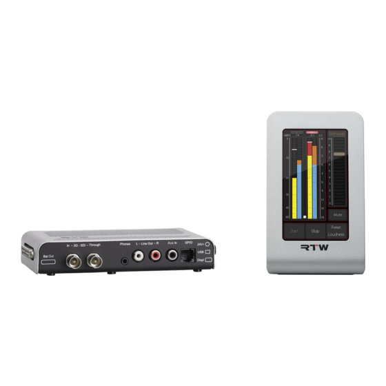
1.2 | Lieferumfang Packen Sie das Instrument aus und prüfen Sie, ob Sie alle entsprechen- den Komponenten erhalten haben. Falls Teile fehlen, wenden Sie sich bitte an Ihren Händler. TouchMonitor TM3-3G TM3-3G (8-Kanal-Anzeige) verbunden Display-Einheit + 3G-SDI-Interfacebox Netzteil Manual 1.3 | Optionen... -
Page 15: Installation
2 | Installation Der TouchMonitor TM3-3G wurde für die freie Platzierung auf Tischen, Pulten, u. a. entwickelt. Das Gerät besteht aus einer Display-Einheit mit 4,3-Zoll Touch Screen und einer abgesetzter 3G-SDI-Interfacebox, die über vielfältige Anschlussmöglichkeiten verfügt und über ein Kabel die Display-Einheit mit Daten und Strom versorgt. -
Page 16: Anschlüsse
2.1 | Anschlüsse Frontansicht der 3G-SDI-Interface-Box GP IO 3G-SDI (RJ-11-6P6C) (BNC In) 3G-SDI Aux In (BNC Through) (RCA) *) Phones Analog Out R (3,5 mm Klinke) *) (RCA) *) *) mit entsprechend freige- Analog Out L schalteter Lizenz! (RCA) *) Manual | TM3-3G DE-14 2 | Installation | 2.1 | Anschlüsse... - Page 17 Anschlüsse (Fortsetzung) Linke Seitenansicht der 3G-SDI-Interface-Box 8 AES3 Out (1 - 8, Sub-D) *) Rechte Seitenansicht der 3G-SDI-Interface-Box Gesteckte Verbindung zur Display-Einheit (2 m, max. 15 m) USB 2.0 Mini-B (USB-Schnittstellenkabel zum Austausch von Daten zwischen Devicer DC1 und TM3-3G erforderlich) 4-pol.
-
Page 18: Pin-Belegung
2.2 | Pin-Belegung „3G-SDI In“, „3G-SDI Through“ (unsymmetrisch, BNC-F) Pin: Funktion: Signal Ring Ring Schirm/Gehäuse (Außenansicht der Einbaubuchse) HINWEIS - Die Eingangssignale werden unbearbeitet durchge- leitet. Blockdiagramm der 3G-SDI-Deembedder-Schnittstelle „USB-Mini-B“ Full-Speed-USB-2.0-Schnittstelle zum Anschluss des TM3-3G mit einem handelsüblichen USB-Datenkabel (Mini-B auf A) an einen Computer. Das USB-Interface dient zum Austausch der Daten zwischen der Device- Confi... - Page 19 Pin-Belegung (Fortsetzung) „Bal.Out“ (AES3, 25-pol. Sub-D-F) Pin: Funktion: Ausgang Digital 8 (+, heiß) P i n 1 P i n 1 4 Ausgang Digital 8 (–, kalt) Paar 8 P i n 2 P i n 1 5 P i n 3 Schirm/Gehäuse P i n 1 6 P i n 4...
- Page 20 Pin-Belegung (Fortsetzung) „Line Out L“, „Line Out R“, „Aux In“ (unsymmetrisch, RCA-F) Pin: Funktion: Ring Pin: Signal (Außenansicht der Einbaubuchse) Ring: Schirm/Gehäuse HINWEIS - Die analogen Signalausgänge der RCA-Buchsen „Line Out“ liegen parallel zu den entsprchenden Ausganssignalen der Kopfhörerbuchse. „GPIO“ (RJ-11-6P6C-Buchse) Externe Steuerung der im Menü...
-
Page 21: Bedienung
• Schließen Sie die vorgesehene Spannungsversorgung an die 3G-SDI- Interface-Box an. Benutzen Sie das zum Lieferumfang gehörende Netzteil RTW 1168-R. • Verbinden Sie das Netzteil mit dem Stromnetz. Nach kurzer Zeit ist der TouchMonitor TM3-3G betriebsbereit. Manual | TM3-3G 3 | Bedienung | 3.1 | Inbetriebnahme DE-19... -
Page 22: Signalquellen Und Synchronisation
3.2 | Signalquellen und Synchronisation Der TouchMonitor TM3-3G besitzt eine Eingangsbuchse für digitale 3G- SDI-Signalquellen. Diese und die verschiedenen Ausgangsanschlüsse sind im Kapitel 2 | Installation im Detail beschrieben. Die Auswahl der ausgelesenen aktiven Audio-Signale für die aktuelle Messung erfolgt durch das Laden eines passenden Presets. -
Page 23: Vertikale Und Horizontale Presets Laden
3.3 | Vertikale und horizontale Presets laden Die Display-Einheit des TouchMonitor TM3-3G kann sowohl vertikal als auch horizontal aufgestellt werden. Für beide Ausrichtungen sind im Ge- rät passende Preset-Versionen gespeichert. Vertikale Ausrichtung Um den TM3-3G im vertikalen Anzeigemodus zu nutzen, bringen Sie die Display-Einheit einfach in die aufrechte Position. - Page 24 Horizontale Ausrichtung Um den TM3-3G im horizontalen Anzeigemodus zu nutzen, kippen Sie die Display-Einheit nach links, so dass sich der Fuß auf der rechten Seite befi ndet. • Wischen Sie mit einem Finger in beliebiger Richtung horizontal über den Bildschirm, um durch die gespeicherten Presets für den Horizon- talbetrieb zu blättern.
-
Page 25: Presets
4 | Presets Der TouchMonitor TM3-3G enthält im Auslieferungszustand Werks-Pre- sets, die einen Querschnitt durch die unterstützten Anwendungsgebiete, Anschlussformate und Standards darstellen. Mit Hilfe dieser Presets kön- nen Sie das Gerät unmittelbar in Betrieb nehmen - auch ohne Anschluss an einen Computer und Installation der Konfi gurations-Software Devicer DC1. - Page 26 Im folgenden Abschnitt sind die wichtigsten Merkmale der gespeicherten Werks-Presets aufgelistet. Dazu gehören auch die vom jeweiligen Preset angesprochenen SDI-Audio-Signale. Nähere Details zu den Anschlüssen fi nden Sie im Kapitel 2 | Installation. HINWEIS - Einige Presets stehen nur zur Verfügung, wenn be- stimmte Lizenz-Optionen aktiviert sind.
- Page 27 2CH SDI ATSC LRA+CORR Eingang (Stereo): SDI: I-1, I-2 Loudness-Standard: ATSC A/85 Program Meter-Skala: TP60: +3 ... –60 dB Instrumente: Korrelator, Program Meter (Stereo-PPM), Loud- ness Numeric, Loudness Sum, LRA mit Tasten Manual | TM3-3G 4 | Presets DE-25...
- Page 28 2CH SDI EBU LRA+CORR Eingang (Stereo): SDI: I-1, I-2 Loudness-Standard: EBU R128 Program Meter-Skala: TP60: +3 ... –60 dB Instrumente: Korrelator, Program Meter (Stereo-PPM), Loud- ness Numeric, Loudness Sum, LRA mit Tasten Manual | TM3-3G DE-26 4 | Presets...
- Page 29 3 X 2CH SDI ATSC Eingang (3 x Stereo): 3 Gruppen mit SDI: I-1, I-2 | I-3, I-4 | II-1, II-2 Loudness-Standard: ATSC A/85 Instrumente: In jeder Gruppe: LRA, Loudness Sum, Korrelator 1 x Global Keyboard für alle Gruppen Manual | TM3-3G 4 | Presets DE-27...
- Page 30 3 X 2CH SDI EBU Eingang (3 x Stereo): 3 Gruppen mit SDI: I-1, I-2 | I-3, I-4 | II-1, II-2 Loudness-Standard: EBU R128 Instrumente: In jeder Gruppe: LRA, Loudness Sum, Korrelator 1 x Global Keyboard für alle Gruppen Manual | TM3-3G DE-28 4 | Presets...
- Page 31 5.1 SDI ATSC LRA Eingang (5.1): SDI: I-1, I-2, I-3, I-4, II-1, II-2 Loudness-Standard: ATSC A/85 Program Meter-Skala: TP60: +3 ... –60 dB Instrumente: Program Meter (5.1-PPM/Loudness), Loudness Sum, LRA mit Tasten Manual | TM3-3G 4 | Presets DE-29...
- Page 32 5.1 SDI EBU LRA Eingang (5.1): SDI: I-1, I-2, I-3, I-4, II-1, II-2 Loudness-Standard: ATSC A/85 Program Meter-Skala: TP60: +3 ... –60 dB Instrumente: Program Meter (5.1-PPM/Loudness), Loudness Sum, LRA mit Tasten Manual | TM3-3G DE-30 4 | Presets...
- Page 33 5.1 SDI ATSC MON (nur darstellbar mit TM3-SWMON) Eingang (5.1): SDI: I-1, I-2, I-3, I-4, II-1, II-2 Loudness-Standard: ATSC A/85 Program Meter-Skala: TP60: +3 ... –60 dB Instrumente: Program Meter (5.1-PPM), Loudness Numeric mit Tasten, Loudness Sum, Monitoring Monitoring-Modus: L/R aus 5.1-Anzeige Manual | TM3-3G 4 | Presets DE-31...
- Page 34 5.1 SDI EBU MON (nur darstellbar mit TM3-SWMON) Eingang (5.1): SDI: I-1, I-2, I-3, I-4, II-1, II-2 Loudness-Standard: EBU R128 Program Meter-Skala: TP60: +3 ... –60 dB Instrumente: Program Meter (5.1-PPM), Loudness Numeric mit Tasten, Loudness Sum, Monitoring Monitoring-Modus: L/R aus 5.1-Anzeige Manual | TM3-3G DE-32 4 | Presets...
- Page 35 5.1+2CH SDI ATSC MON (nur darstellbar mit TM3-SWMON) Eingang 5.1-Gruppe: SDI: I-1, I-2, I-3, I-4, II-1, II-2 Eingang 2CH-Gruppe: SDI: II-3, II-4 Loudness-Standard: ATSC A/85 Program Meter-Skala: Jeweils TP60: +3 ... –60 dB Instrumente: Program Meter (5.1-PPM, 2-Kanal-Stereo-PPM), Loudness Sum (5.1, 2CH), Monitoring 1 x Global Keyboard für beide Gruppen Monitoring-Modus: L/R aus 5.1-Anzeige...
- Page 36 5.1+2CH SDI EBU MON (nur darstellbar mit TM3-SWMON) Eingang 5.1-Gruppe: SDI: I-1, I-2, I-3, I-4, II-1, II-2 Eingang 2CH-Gruppe: SDI: II-3, II-4 Loudness-Standard: EBU R128 Program Meter-Skala: Jeweils TP60: +3 ... –60 dB Instrumente: Program Meter (5.1-PPM, 2-Kanal-Stereo-PPM), Loudness Sum (5.1, 2CH), Monitoring 1 x Global Keyboard für beide Gruppen Monitoring-Modus: L/R aus 5.1-Anzeige...
- Page 37 8CH ATSC SDI STATUS Eingang (Mehrkanal): SDI: I-1, I-2, I-3, I-4, II-1, II-2, II-3, II-4 Loudness-Standard: ATSC A/85 Program Meter-Skala: TP60: +3 ... –60 dB Instrumente: Program Meter (8-Kanal-PPM/Loudness), SDI Status mit Tasten Manual | TM3-3G 4 | Presets DE-35...
- Page 38 8CH EBU SDI STATUS Eingang (Mehrkanal): SDI: I-1, I-2, I-3, I-4, II-1, II-2, II-3, II-4 Loudness-Standard: EBU R128 Program Meter-Skala: TP60: +3 ... –60 dB Instrumente: Program Meter (8-Kanal-PPM/Loudness), SDI Status mit Tasten Manual | TM3-3G DE-36 4 | Presets...
- Page 39 8CH SDI GROUP I+II Eingang (Mehrkanal): SDI: I-1, I-2, I-3, I-4, II-1, II-2, II-3, II-4 Loudness-Standard: EBU R128 Program Meter-Skala: TP60: +3 ... –60 dB Instrumente: Program Meter (8-Kanal-PPM) Manual | TM3-3G 4 | Presets DE-37...
- Page 40 8CH SDI GROUP III+IV Eingang (Mehrkanal): SDI: III-1, III-2, III-3, III-4, IV-1, IV-2, IV-3, IV-4 Loudness-Standard: EBU R128 Program Meter-Skala: TP60: +3 ... –60 dB Instrumente: Program Meter (8-Kanal-PPM) Manual | TM3-3G DE-38 4 | Presets...
-
Page 41: Instrumente
5 | Instrumente Im TouchMonitor TM3-3G stehen die nachfolgend beschriebenen Instru- mente zur Verfügung, die jeweils unterschiedliche Parameter der gemes- senen Audiosignale visualisieren. Die meisten dieser Instrumente wurden in den Werks-Presets auf verschiedene Weise miteinander kombiniert. Verwenden Sie bitte die Konfi gurations-Software Devicer DC1, um die Instrumenten-Auswahl oder die Bildschirmaufteilung eines Presets zu verändern oder eigene Presets zu erstellen. -
Page 42: Program Meter
5.1 | Program Meter Signalpegel Loudness Beispiel: Program Meter im 5.1-Modus mit kombi- nierter Pegel- und Loudness-Anzeige Das Program Meter bietet eine vertikale oder horizontale Bargraph- Anzeige für die Einzelkanäle der aktiven Signalquelle. Das Instrument zeigt pro Kanal entweder den Signalpegel, die Loudness oder eine Kom- bination aus beiden an. - Page 43 Die in den Werks-Presets in Gelb dargestellten Signalpegel können je nach Konfi guration des Presets nach zwei unterschiedlichen Verfahren angezeigt werden. Sie stehen für jeden Einzelkanal wahlweise als tradi- tionelle Quasi-Peakmeter (PPMs) mit verschiedenen wählbaren Skalen (DIN, British, Nordic etc.) oder aber mit der nach aktuellen Standards neu eingeführten True Peak-Skala zur Verfügung.
-
Page 44: Loudness Sum
5.2 | Loudness Sum Skalenmarke Toleranz- für den bereich Target Level Momentary- Shortterm- Bargraph M Bargraph S Beispiel: Loudness Sum-Instrument im EBU-Modus zeigt Momentary-Bargraph M und Shortterm-Bargraph S. Der Integrated-Bargraph I ist ausgeblendet. Das Loudness Sum-Instrument gibt die aus allen Einzelkanälen eines Signals kombinierte Gesamt-Loudness mit bis zu drei Bargraphen an, die Messungen mit unterschiedlichen Zeitkonstanten repräsentieren. - Page 45 Die drei im Loudness Sum-Instrument darstellbaren Bargraphen zeigen: • M (Momentary): Summierung der Momentary-Loudnessmessungen in den Einzelkanälen mit 400 ms Integrationszeit. • S (Shortterm): Summierte Loudness-Messung mit einer Integrati- onszeit von 3 s mit gleitendem Fenster. • I (Integrated): Gesamt-Loudness des Programms zwischen einem manuell gesetzten Anfangs- und Endpunkt.
-
Page 46: Lra
5.3 | LRA Skalenmarke für den Target Level LRA-Low-Range-Bereich Numerischer LRA-Wert Aktueller Integrated-Wert I LRA-Comfort-Zone-Bereich Integrated-Bargraph I LRA-High-Range-Bereich Beispiel: LRA-Instrument im „MagicLRA + I + Num“-Modus mit Integrated-Bargraph (I) und numerischer Anzeige Das LRA-Instrument bietet eine grafi sche Darstellung der Loudness Ran- ge (LRA). - Page 47 Für LRA-Messungen existiert in den Loudness-Standards keine einheitli- che Zielgröße. Allerdings werden die drei farblich unterschiedlich markier- ten Bereiche „Comfort Zone“ (mittlere LRA-Werte), „High Range“ (hohe LRA-Werte) und „Low Range“ (niedrige LRA-Werte) unterschieden, in die ein Programm abhängig von seinem gemessenen LRA-Wert eingeordnet werden kann.
-
Page 48: Loudness Numeric
5.4 | Loudness Numeric Aktueller Momentary- Aktueller Wert M Shortterm- Aktueller Wert S Integrated- Aktueller Wert I LRA-Wert Maximaler True Peak- Maximaler Wert TPmax Momentary- Maximaler Wert Mmax Shortterm- Wert Smax Beispiel: Loudness Numeric-Instrument zeigt alle Werte: Momentary (M), Shortterm (S), Integrated (I), LRA, TPmax, Mmax und Smax. Laufende Messungen sind grün dargestellt, Überschreitungen rot. - Page 49 Das Instrument Loudness Numeric bietet eine numerische Darstellung der folgenden Loudness-Messwerte: • M (Momentary): Summierung der Momentary-Loudnessmessungen in den Einzelkanälen mit 400 ms Integrationszeit. • S (Shortterm): Summierte Loudness-Messung mit einer Integrati- onszeit von 3 s mit gleitendem Fenster. • I (Integrated): Gesamt-Loudness des Programms zwischen einem manuell gesetzten Anfangs- und Endpunkt.
-
Page 50: Correlator
5.5 | Correlator Positiver Negativer Bereich Bereich (grün) (rot) Beispiel: Korrelation ist zwischen +0,3 bis +0,7 (Vollauschlag bedeutet +1) Der Correlator zeigt die Phasenbeziehungen zwischen den beiden Kanä- len eines Stereosignals und damit seine Mono-Kompatibilität an. Identische Signale in beiden Kanälen haben die Korrelation +1, vollstän- dig unabhängige Signale eine Korrelation von 0. -
Page 51: Global Keyboard
5.6 | Global Keyboard Beispiel: Start-, Stop- und Reset-Tasten zur globalen Steuerung von Loudness-Instrumenten Das Global Keyboard-Instrument kann bis zu zehn Tasten enthalten, die sich auf unterschiedliche Weise nutzen lassen. Jede Taste, die auf den Modus „Instrument“ eingestellt ist, kann Funktionen mehrerer Instrumente steuern, auch wenn sich diese in unterschiedlichen Audio-Gruppen befi... -
Page 52: Dialnorm
5.7 | Dialnorm Aktueller Kanäle Modus für die Messung Status der Messung: Max. Mess- Stopp (gelb) dauer Running (grün) Vergange- ne Mess- Leq(k) als dauer Signal-Pegel bezogen auf 0 dBFS Aktueller Dialnorm- Wert Steuer- tasten Beispiel: Die Kanäle L und R sind gewählt, die Berechnung ist noch nicht gestartet (gelb) Das Dialnorm-Instrument wird zur Berechnung numerischer Dialnorm- Werte aus digitalen Surround-Signalen verwendet. - Page 53 Dies basiert auf der Annahme, dass die empfundene Gesamtlautstärke einer Mischung durch den Bezug auf die Sprache (optimierte Sprachver- ständlichkeit bzw. minimierte Störwirkung durch zu laute Sprache) wegen der festen Lautstärkeverhältnisse zwischen Sprache, Musik und Ge- räuscheffekten innerhalb einer Mischung ermittelt bzw. durch geeignete Maßnahmen beim Empfänger relativ gut konstant gehalten werden kann.
-
Page 54: Monitoring
5.8 | Monitoring Schieberegler (per Finger steuerbar) SPL-Pegel-Skala Funktionstasten Beispiel: Der Schieberegler für das Monitoring mit den zusätzlichen Funktionstasten Das Monitoring-Instrument mit dem kalibrierbaren On-Screen-Schie- beregler zur Einstellung der Abhörlautstärke ist Teil der Monitoring-Con- trol-Funktion zum Abhören angezeigter Audio-Signale und steht mit der Aktivierung der Monitoring-Lizenz-Option TM3-SWMON zur Verfügung. - Page 55 Mit dieser Lizenz können die angezeigten Audio-Signal je nach Format direkt oder als Downmix auf die Ausgänge Line Out L/R (RCA) bzw. Pho- nes (3,5 mm Klinke) geroutet und analog zum Abhören ausgegeben wer- den. Der auf dem Bildschirm positionierte Schieberegler ermöglicht die Anpassung der Abhörlautstärke.
-
Page 56: Aes-Status
5.9 | AES-Status Anzeige von: • Kanal-Status • Binär-Daten • Common (abgebildet) • Audio-Bits • Aktive Bits Funktions- tasten Beispiel: Der Statusmonitor mit der Common-Ansicht Die im SDI-Datenstrom eingebetteten Audio-Signale liegen in der Regel im AES3-Format vor. Im Statusmonitor (AES-Status) werden die darin ent- haltenen Status-Bytes als Klartext oder Binärdaten angezeigt. -
Page 57: Sdi Interface
5.10 | SDI Interface Das SDI Interface-Instrument zeigt den Status der 3G/HD/SD-SDI- Deembedder-Schnittstelle an. Neben der Angabe des SDI- und des Video-Formats werden die im Datenstrom enthaltenen Audio-Signale und Signal-Gruppen aufgelistet. Werks-Presets mit SDI Interface-Instrument: • Keine Manual | TM3-3G 5 | Instrumente | 5.10 | SDI Interface DE-55... -
Page 58: Moving Coil
5.11 | Moving Coil Beispiel: PPM-Anzeige im Dual-L/R-Modus links neben Dual-M/S- Modus bei horizontaler Ausrichtung des TM3 Das Moving-Coil-Instrument erweitert den Funktionsumfang des TM3 bzw. TM3-6CH mit der Darstellung von Zeigerinstrumenten. Diese ste- hen mit der Aktivierung der Moving-Coil-Lizenz-Option TM3-SWMC zur Verfügung. -
Page 59: Firmware-Update
Verfügung stehen, die zum Zeitpunkt der Veröffentlichung der installierten Firmware-Version erhältlich waren. Firmware-Updates erhalten Sie im Mitglieder-Bereich der RTW-Webseite oder über Ihren Vertriebspartner. Das Firmware-Update ist denkbar einfach durchzuführen: Der TM3 wird wie ein USB-Laufwerk an den Computer angeschlossen und die Update- Datei direkt auf dem TM3 gespeichert. - Page 60 Schließen Sie den betriebsbereiten TM3 mittels eines handelsübli- chen USB-Interface-Kabels (A auf Mini-B) an den Computer an. Das Computer-System erkennt den TM3 als Laufwerk RTW-TM3. Loggen Sie sich im Mitglieder-Bereich der RTW-Webseite (http:// www.rtw.de/sales-support/manuals-software.html) ein und klicken Sie unter Audio-Monitore auf die Option, die Ihrem TM3 entspricht.
- Page 61 Windows® Klicken Sie auf die Update-Datei (rtw-tm-fw-n-n.bin, n-n: Version). Das Dialog-Feld Dateidownload öffnet sich. Klicken Sie auf die Schaltfl äche Speichern. Manual | TM3 6 | Firmware-Update | Windows® DE-59...
- Page 62 Wählen Sie im Dialog-Feld Speichern unter im Kombinationsfeld Speichern in: das Laufwerk RTW-TM3 aus. Klicken Sie auf die Schaltfl äche Speichern. Die Firmware-Update- Datei wird jetzt auf den TM3 gespeichert. Manual | TM3 DE-60 6 | Firmware-Update | Windows®...
- Page 63 Fahren Sie mit Schritt 14 fort. Mac OS X® Zeigen Sie auf die Update-Datei (rtw-tm-fw-n-n.bin, n-n: Version), halten Sie die Ctrl-Taste gedrückt und klicken Sie auf die Datei. Manual | TM3 6 | Firmware-Update | Mac OS X® DE-61...
- Page 64 10. Klicken Sie im angezeigten Menü auf Verknüpfte Datei laden un- ter ... Das Dialog-Feld Speichern unter öffnet sich. 11. Klicken Sie auf das Kombinationsfeld Ort und klicken Sie im ange- zeigten Menü auf die Option RTW-TM3. Manual | TM3 DE-62...
- Page 65 12. Wenn RTW-TM3 neben Ort angezeigt ist, klicken Sie auf Sichern. Die Firmware-Update-Datei wird jetzt auf den TM3 gespeichert. 13. Fahren Sie mit Schritt 14 fort. Manual | TM3 6 | Firmware-Update | Mac OS X® DE-63...
- Page 66 14. Melden Sie nach erfolgtem Download den TM3 wie ein USB-Lauf- werk ordnungsgemäß vom Computer-System ab! Ziehen Sie erst dann das USB-Kabel vom Computer oder vom TM3 ab! ACHTUNG! - Die Abmeldung vom Computer ist erforder- lich, um eine Beschädigung der kopierten Datei zu vermeiden! 15.
-
Page 67: Technische Daten
7 | Technische Daten System Allgemein Spannungsversorgung: +24 V DC (externe Überstrombegrenzung auf 2 A erfor- derlich!) Stromaufnahme: 160 mA Nennstrom, Einschaltstrom deutlich höher Display: 4,3’’-TFT Touch-Screen 272 x 480 Pixel Anschlüsse: • 1 x 4-pol. Kleinspannungsstecker Typ 710 (DC) •... - Page 68 Technische Daten (Fortsetzung) • Dialnorm-Messung (ohne speech intelligence) • SDI-Statusmonitor • Numerische Anzeigen • 16-Kanal-3G/HD/SD-SDI-Deembedder • Routing ausgelesener Audio-Signale auf AES3-Aus- gänge (Lizenzoption) • Abhör-Controller mit Onscreen-Pegelregler (Lizenzoption) • Moving-Coil-Anzeige (Lizenzoption) Digitale Eingänge Eingänge: 1 x 3G-SDI In (unsymmetrisch), BNC-F Ausgänge: 1 x 3G-SDI Through (unsymmetrisch), BNC-F, aktive, unbearbeitete Durchleitung...
- Page 69 Technische Daten (Fortsetzung) Anzeigen: • Spitzenpegel • Peak-Hold • Numerischer Wert der Anzeige Funktionen: • Gain (+20 dB, +40 dB je nach Standard) • Peak-Hold ein/aus • Memory • Reset Digitale Peakmeter Wortbreite: 24 Bit Digitale Skalen: • TP60: +3 .. –60 dB •...
- Page 70 Technische Daten (Fortsetzung) SDI-Status-Monitor Anzeige: • Kanal-Daten in Klartext-, Hexadezimal- oder Binär- Darstellung • Kanal einstellbar • Audio-Bit-Aktivität • Hardware-Status Global Keyboard Globales Tastenfeld zur Steuerung defi nierter Funktionen in verschiedenen Instrumenten und zum Preset-Aufruf, ermöglicht auch die externe Steuerung über die GP IO- Schnittstelle Loudness- und SPL-Anzeige EBU-R128-Loudness-Modus...
- Page 71 Technische Daten (Fortsetzung) • ITU+9: +9 .. –18 LU • ITU0: 0 .. –30 LKFS • ATSC0: 0 .. –60 LKFS • ATSC0a: 0 .. –30 LKFS Bewertungsfi lter: K-Filter entsprechend ITU-R BS.1770 Zielwert (Target Level): *) –23 LUFS; einstellbar im Bereich von –10 bis –30 LUFS Time &...
- Page 72 Technische Daten (Fortsetzung) Loudness Range Instrument (LRA) Anzeige: Grafi sche Darstellung der Loudness Range Modus: wählbar: LRA Bar, MagicLRA, MagicLRA + I, MagicLRA + I + Num Skalenbereich: wählbar: 6 LU, 10 LU, 20 LU, 30 LU Minimalbereich: 2 LU; einstellbar von 1 bis 20 LU (1-LU-Schritte) Komfortbereich: 4 LU;...
- Page 73 Technische Daten (Fortsetzung) TM3-SWMC: Moving Coil (Software-Lizenz) Software-Lizenz zur Erweiterung des Funktionsumfang um das Moving-Coil- Instrument zur Darstellung von Zeigerinstrumenten für bis zu 2-Kanal-Stereo mit verschiedenen Skalen. Anzeigen-Typ: PPM (L/R), PPM (M/S), VU, Loudness, PPM + Loudness (L/R; M, S oder I), wählbar PPM: - Kanalanordnung: Dual, Dual + M/S horizontal, Dual + M/S vertikal, Stereo...
- Page 74 Technische Daten (Fortsetzung) Lieferumfang TouchMonitor TM3-3G: • 2-Kanal-Stereo bis 8-Kanal • TM3-Display-Einheit mit 4,3“-Touch-Screen im Tisch- gehäuse mit angeschlagenem Verbindungskabel • damit verbundene 3G-SDI-Interface-Box • Netzteil, Manual Bestellnr.: TM3-3G Optionale Software-Lizenzen • Software-Lizenz TM3-SWMON zur nachträglichen Erweiterung um eine Monitoring-Control-Funktion zum Abhören angezeigter Audio-Signale...
-
Page 75: Ce-Konformität
8 | CE-Konformität EG-Konformitätserklärung | Richtlinie 2004/108/EG und Richtlinie 2006/95/EG Wir, die RTW GmbH & Co.KG, Am Wassermann 25, 50829 Köln, Deutschland, erklären in alleiniger Verantwortung, dass das Produkt: RTW TouchMonitor TM3-3G (Tischgerät, bestehend aus Display-Einheit und 3G-SDI-Interface-Box, inklusive Verbindungskabel und Netzteil) auf das sich diese Erklärung bezieht, mit den folgenden Normen bzw. -
Page 76: Lizenzen
Die Produkte der TouchMonitor TM3 Serie umfassen neben der Hardware ein Soft- warepaket, das Programme mit unterschiedlichen Lizenzen beinhaltet: A. Software aus der Urheberschaft der RTW GmbH & Co.KG, die nur zum bestim- mungsmäßen Gebrauch des Gerätes verwendet werden darf (Applikation, DSP- Programme, Bootloader). - Page 77 Die Lizenz fi nden Sie unter http://www.openssl.org/source/license.html. An der unter B. aufgeführten Software wurden teilweise Änderungen vorgenom- men. In diesem Fall können Sie die Sourcen der geänderten Software von RTW auf Anfrage innerhalb von drei Jahren nach Erhalt des Gerätes zugesandt bekommen.
-
Page 78: Blockdiagramm
Blockdiagramm © 06/2013 | Technische Änderungen vorbehalten. RTW GmbH & Co. KG Am Wassermann 25 | 50829 Köln | Germany Phone: +49 221. 70 913-0 | Fax: +49 221. 70 913-32 Internet: www.rtw.de | E-Mail: rtw@rtw.de... - Page 79 TouchMonitor TM3-3G Operating Manual...
- Page 80 2.5 and higher | June 2013 © 2013 | Technical changes without prior notice! RTW GmbH & Co.KG | Am Wassermann 25 | 50829 Köln | Germany Fon +49 221. 70 913-0 | Fax +49 221. 70 913-32 www.rtw.de | rtw@rtw.de WEEE Reg.-no.:...
- Page 81 Safety Instructions The following symbols may be marked on the panels or covers of equip- ment or module and are used in this manuals with these terms: WARNING! This symbol alerts you to a potentially hazardous condition, such as the presence of dangerous voltage that could pose a risk of electrical shock.
- Page 82 • Never remove any parts from the unit and do not make any modifi ca- tions to the unit without the express written consent of RTW. Modifi - cations can cause both safety hazards and affect the unit’ s EMI-CE conformity.
- Page 83 • Use with power supply model STD-2427PA, manufactured by Adapter Technology Co Ltd. (RTW 1168-R). • The power cord of the external power supply disconnects the product from the power source. Do not block the power cord or power supply;...
- Page 84 ATTENTION! Always follow the safety precautions below to avoid the possibility of physical injury to you or others, or damage to the unit or other property. These precautions include, but are not limited to, the following: • Do not block any ventilation openings. Install in accordance with the manufacturer‘s instructions to prevent the internal temperature from becoming too high.
- Page 85 Environmental Considerations Observe the following information about the environmental impact of the product and the following guidelines when recycling an instrument or component (product end-of-life handling): • Equipment Recycling Production of this equipment required the extraction and use of natural resources.
- Page 86 Content Safety Instructions Important Safety Instructions Warning! Attention! Environmental Considerations Content 1 | Before You Begin 1.1 | Design Concept 1.2 | Scope of Delivery 1.3 | Options 1.4 | Accessories 2 | Installation 2.1 | Connection 2.2 | Pin Assignment 3 | Operation 3.1 | System Start-up 3.2 | Signal Sources and Synchronization...
-
Page 87: Before You Begin
1 | Before You Begin 1.1 | Design Concept Thank you for purchasing the TouchMonitor TM3-3G made by RTW. You have settled for a highly effi cient metering solution based on modern hardware and most recent technology that combines intuitive, easy operation with a high degree of fl... - Page 88 Being a stand-alone unit using an elegant touchscreen-based preset control, the TouchMonitor TM3-3G will always provide you with the exact audio signal information that you will need for fast and safe interpretation even without having a profound technical background. The high-contrast 4.3“...
- Page 89 When it comes to confi guring local presets using the soft- Devicer DC1 ware application (Windows® and Mac OS X® compatible), the TM3-3G‘s power and fl exibility really shines. Besides PPM and True Peak instruments, the TM3-3G features comprehensive loudness measuring options confor- ming to all relevant international standards (EBU R128, ITU-R BS.1770-3/ 1771, ATSC A/85, and ARIB).
-
Page 90: Scope Of Delivery
1.2 | Scope of Delivery Unpack the instrument and check, if you received all items listed. If com- ponents are missing, please contact your dealer. TouchMonitor TM3-3G TM3-3G (8-channel display) connected Display Unit + 3G-SDI Interfacebox Power Supply Manual 1.3 | Options... -
Page 91: Installation
2 | Installation The TouchMonitor TM3-3G units are designed for free positioning on tab- les, desks, et. al. A TM3-3G unit consist of a display unit with 4.3 inch touch screen and a separate 3G-SDI interfacebox featuring many capabilities of connecting. The connected cable supplies the display unit with power and data. -
Page 92: Connection
2.1 | Connection Front View of the 3G-SDI Interface Box GP IO 3G-SDI (RJ-11-6P6C) (BNC In) 3G-SDI Aux In (BNC Through) (RCA) *) Phones Analog Out R (3.5 mm jack) *) (RCA) *) *) with corresponding Analog Out L licence option activated! (RCA) *) Manual | TM3-3G EN-14... - Page 93 Connection (continued) Left Side View of the 3G-SDI Interface Box 8 AES3 Out (1 - 8, Sub-D) *) Right Side View of the 3G-SDI Interface Box Connected to display unit (2 m, max. 15 m) USB 2.0 Mini-B (USB interface cable for the exchange of Devicer DC1 and TM3-3G data required) 4-pin locking low voltage connector...
-
Page 94: Pin Assignment
Full Speed USB 2.0 interface for connecting the TM3-3G unit to the computer using a standard USB data cable. The USB interface is used for the data exchange between Device Confi gurator software Devicer DC1 and TouchMonitor TM3-3G. Manual | TM3-3G EN-16... - Page 95 Pin Assignment (continued) Bal.Out (AES3, 25-pin Sub-D-F) Pin: Function: Digital output 8 (+, hot) P i n 1 P i n 1 4 Digital output 8 (–, cold) pair 8 P i n 2 P i n 1 5 Shield/chassis P i n 3 P i n 1 6 P i n 4...
- Page 96 Pin Assignment (continued) Line Out L, Line Out R, Aux In (unbalanced, RCA-F) Pin: Function: Ring Signal (External view of the connector) Shield/chassis Ring The analog signal outputs of the Line Out RCA connec- NOTE - tors are in parallel with the corresponding output signals of the phones connector.
-
Page 97: Operation
RTW 1168-R supplied with the TM3-3G. • Connect the power supply to the mains supply. After a short boot-up sequence, the TouchMonitor TM3-3G will be ready for use. Manual | TM3-3G 3 | Operation | 3.1 | System Start-up... -
Page 98: Signal Sources And Synchronization
Allocated to two presets all au- dio signals may then be monitored. Synchronization TouchMonitor TM3-3G handles the typical sampling rates (48 kHz, 24 bit) of audio signals included in an SDI data stream. It synchronizes automati- cally to the connected SDI input signal . -
Page 99: Loading Vertical And Horizontal Presets
3.3 | Loading vertical and horizontal Presets The TM3-3G‘s display can be used in vertical as well as horizontal display modes. For both orientations, suitable preset versions are stored in the unit. Vertical display mode In order to use the TM3-3G in vertical display mode, just place the display unit in its upright position. - Page 100 Horizontal display mode In order to use the TM3-3G in horizontal display mode, rotate the display unit to the left so that the base is positioned on the right hand side. Wipe across the touchscreen with your fi nger in horizontal direction to switch the unit to horizontal display mode and to browse through the available presets in that mode.
-
Page 101: Presets
NOTE - Please note that editing the factory presets or creating your own individual presets is only possible using the RTW Devicer DC1 confi guration software (Windows® and Mac OS X® compatible). This... - Page 102 The following listing describes the most important features of all factory presets. The SDI audio signals used by each preset are also listed. The pin- outs of the connectors are described in detail in chapter 2 | Installation. NOTE - Some presets are only available with specifi c licence options activated.
- Page 103 2CH SDI ATSC LRA+CORR Input (Stereo): SDI: I-1, I-2 Loudness standard: ATSC A/85 Program Meter scale: TP60: +3 ... –60 dB Instruments: Correlator, Program Meter (Stereo-PPM), Loud- ness Numeric, Loudness Sum, LRA with keys Manual | TM3-3G 4 | Presets EN-25...
- Page 104 2CH SDI EBU LRA+CORR Input (Stereo): SDI: I-1, I-2 Loudness standard: EBU R128 Program Meter scale: TP60: +3 ... –60 dB Instruments: Correlator, Program Meter (Stereo-PPM), Loud- ness Numeric, Loudness Sum, LRA with keys Manual | TM3-3G EN-26 4 | Presets...
- Page 105 3 X 2CH SDI ATSC Input (3 x Stereo): 3 groups with SDI: I-1, I-2 | I-3, I-4 | II-1, II-2 Loudness standard: ATSC A/85 Instruments: In each group: LRA, Loudness Sum, Correlator 1 x Global Keyboard for all groups Manual | TM3-3G 4 | Presets EN-27...
- Page 106 3 X 2CH SDI EBU Input (3 x Stereo): 3 groups with SDI: I-1, I-2 | I-3, I-4 | II-1, II-2 Loudness standard: EBU R128 Instruments: In each group: LRA, Loudness Sum, Correlator 1 x Global Keyboard for all groups Manual | TM3-3G EN-28 4 | Presets...
- Page 107 5.1 SDI ATSC LRA Input (5.1): SDI: I-1, I-2, I-3, I-4, II-1, II-2 Loudness standard: ATSC A/85 Program Meter scale: TP60: +3 ... –60 dB Instruments: Program Meter (5.1-PPM/Loudness), Loudness Sum, LRA with keys Manual | TM3-3G 4 | Presets EN-29...
- Page 108 5.1 SDI EBU LRA Input (5.1): SDI: I-1, I-2, I-3, I-4, II-1, II-2 Loudness standard: ATSC A/85 Program Meter scale: TP60: +3 ... –60 dB Instruments: Program Meter (5.1-PPM/Loudness), Loudness Sum, LRA with keys Manual | TM3-3G EN-30 4 | Presets...
- Page 109 5.1 SDI ATSC MON (only available with TM3-SWMON) Input (5.1): SDI: I-1, I-2, I-3, I-4, II-1, II-2 Loudness standard: ATSC A/85 Program Meter scale: TP60: +3 ... –60 dB Instruments: Program Meter (5.1-PPM), Loudness Numeric with keys, Loudness Sum, Monitoring Monitoring mode: L/R of 5.1 display Manual | TM3-3G...
- Page 110 5.1 SDI EBU MON (only available with TM3-SWMON) Input (5.1): SDI: I-1, I-2, I-3, I-4, II-1, II-2 Loudness standard: EBU R128 Program Meter scale: TP60: +3 ... –60 dB Instruments: Program Meter (5.1-PPM), Loudness Numeric with keys, Loudness Sum, Monitoring Monitoring mode: L/R of 5.1 display Manual | TM3-3G...
- Page 111 5.1+2CH SDI ATSC MON (only available with TM3-SWMON) Input 5.1 group: SDI: I-1, I-2, I-3, I-4, II-1, II-2 Input 2CH group: SDI: II-3, II-4 Loudness standard: ATSC A/85 Program Meter scale: Each with TP60: +3 ... –60 dB Instruments: Program Meter (5.1 PPM, 2-ch. Stereo PPM), Loudness Sum (5.1, 2CH), Monitoring 1 x Global Keyboard for both groups Monitoring mode:...
- Page 112 5.1+2CH SDI EBU MON (only available with TM3-SWMON) Input 5.1 group: SDI: I-1, I-2, I-3, I-4, II-1, II-2 Input 2CH group: SDI: II-3, II-4 Loudness standard: EBU R128 Program Meter scale: Each with TP60: +3 ... –60 dB Instruments: Program Meter (5.1 PPM, 2-ch. Stereo PPM), Loudness Sum (5.1, 2CH), Monitoring 1 x Global Keyboard for both groups Monitoring mode:...
- Page 113 8CH ATSC SDI STATUS Input (Multichannel): SDI: I-1, I-2, I-3, I-4, II-1, II-2, II-3, II-4 Loudness standard: ATSC A/85 Program Meter scale: TP60: +3 ... –60 dB Instruments: Program Meter (8-channel PPM/Loudness), SDI Status with keys Manual | TM3-3G 4 | Presets EN-35...
- Page 114 8CH EBU SDI STATUS Input (Multichannel): SDI: I-1, I-2, I-3, I-4, II-1, II-2, II-3, II-4 Loudness standard: EBU R128 Program Meter scale: TP60: +3 ... –60 dB Instruments: Program Meter (8-channel PPM/Loudness), SDI Status with keys Manual | TM3-3G EN-36 4 | Presets...
- Page 115 8CH SDI GROUP I+II Input (Multichannel): SDI: I-1, I-2, I-3, I-4, II-1, II-2, II-3, II-4 Loudness standard: EBU R128 Program Meter scale: TP60: +3 ... –60 dB Instruments: Program Meter (8-channel PPM) Manual | TM3-3G 4 | Presets EN-37...
- Page 116 8CH SDI GROUP III+IV Input (Multichannel): SDI: III-1, III-2, III-3, III-4, IV-1, IV-2, IV-3, IV-4 Loudness standard: EBU R128 Program Meter scale: TP60: +3 ... –60 dB Instruments: Program Meter (8-channel PPM) Manual | TM3-3G EN-38 4 | Presets...
-
Page 117: Instruments
5 | Instruments The following instrument types are available with the TouchMonitor TM3- 3G to visualize individual aspects of the audio signals measured. The fac- tory presets are using various combinations of these instruments. Please use the Devicer DC1 confi guration software in order to edit any preset‘s choice of instruments and layout or to create your own presets. -
Page 118: Program Meter
5.1 | Program Meter Signal level Loudness Example: Program Meter in 5.1 mode with combi- ned level and Loudness display The Program Meter provides vertical or horizontal bargraph displays for the individual channels of the active signal source. The signal level, the loudness or a combination of both are displayed for each channel. - Page 119 The signal levels for each channel, displayed in yellow in the factory pre- sets, can be presented in two distinct modes, depending on the preset confi guration used. The traditional mode is the Quasi-Peakmeter (PPM), using one of the common scales such as DIN, British or Nordic. Alterna- tively, the single channel signal levels can be displayed using the newly developed True Peak scale conforming to the most recent standards.
-
Page 120: Loudness Sum
5.2 | Loudness Sum Scale mark for Tolerance Target Level range Momentary Shortterm bargraph M bargraph S Example: Loudness Sum instrument in EBU mode shows Momentary bargraph M and Shortterm bargraph S. The Integrated bargraph I is hidden. The Loudness Sum instrument shows the combined total loudness consisting of the summed single channels of a signal. - Page 121 The bargraphs available in the Loudness Sum instrument show the following: • M (Momentary): Summed momentary loudness measurements of the individual channels using an integration time of 400 ms. • S (Short Term): Summed loudness measurement using an integration time of 3 s and a sliding window. •...
-
Page 122: Lra
5.3 | LRA Scale mark for Target Level LRA low range Numerical LRA value Current Integrated I value LRA comfort zone Integrated bargraph I LRA high range Example: LRA instrument in „MagicLRA + I + Num“ mode with Integrated bargraph (I) and numerical display The LRA instrument provides a graphical representation of the Loudness Range (LRA) descriptor. - Page 123 There are no common target LRA values defi ned in the loudness stan- dards. Nevertheless, the three distinct areas „Comfort Zone“ (average LRA values), „High Range“ (high LRA values) and „Low Range“ (low LRA values) are used that can help to classify a program with regard to its LRA measurement and mark it with a distinct color.
-
Page 124: Loudness Numeric
5.4 | Loudness Numeric Current Momentary Current M value Shortterm Current S value Integrated Current I value LRA value Maximum True Peak Maximum value TPmax Momentary Maximum value Mmax Shortterm value Smax Example: Loudness Num instrument shows all values: Momentary (M), Short- term (S), Integrated (I), LRA, TPmax, Mmax und Smax. - Page 125 The Loudness Num instrument provides numerical readouts of the follo- wing loudness measurements: • M (Momentary): Summed momentary loudness measurements of the individual channels using an integration time of 400 • S (Short Term): Summed loudness measurement using an integration time of 3 s and a sliding window.
-
Page 126: Correlator
5.5 | Correlator Negative Positive range range (red) (green) Example: Correlation is between +0,3 to +0,7 (full-scale defl ection means +1) The Correlator instrument displays the phase relationship between the two channels of a stereo signal and thus its mono compatibility. Identical signals in both channels have a correlation of +1;... -
Page 127: Global Keyboard
5.6 | Global Keyboard Example: Start, Stop, and Reset keys for global control of Loudness instruments The Global Keyboard instrument can be set to contain up to 10 keys that can be used in various ways. Each key set to „Instrument“ mode can control functions of several instruments even if they are placed in different Audio Groups. -
Page 128: Dialnorm
5.7 | Dialnorm Current Channels mode for mete- ring Measuring status: Max. meas. Stop: yellow duration Running: green Elapsed meas. Leq(k) as duration signal level refered to 0 dBFS Current Dialnorm value Control keys Example: L and R channels selected, the measuring didn‘t start yet (yellow) The Dialnorm instrument can calculate and show Dialnorm values from its digital input signals. - Page 129 The idea behind this scheme is that the perceived total loudness of a mixed audio signal may be determined and kept constant at the listening end by using the dialogue level (optimized for a combination of good intelligibility and minimal nuisance through excessive volumes) with its fi xed loudness ratio in relation to music and sound effects as a reference.
-
Page 130: Monitoring
5.8 | Monitoring Level fader (control with a fi nger) SPL level scale Function keys Example: The level fader for the monitoring with the additional funkcion keys The Monitoring instrument with its calibratable onscreen level fader for adjusting the monitoring volume is part of the monitoring control function for monitoring of displayed audio signals. - Page 131 With this licence any displayed audio signal depending on the used for- mat can be routed directly or as a downmix to the Line Out L/R (RCA) resp. Phones (3.5 mm jack) analog outputs for monitoring. The level fader positioned on the screen allows the volume adjustment. Additionally, Dim and Mute functions keys can be displayed to dim or to mute the volume just by a fi...
-
Page 132: Aes Status
5.9 | AES Status Display of: • Channel status • Binary data • Common (pictured) • Audio bits • Active bits Function keys Example: The status monitor with Common selected The audio signals in a SDI data stream are normally embedded as AES3 signals. -
Page 133: Sdi Interface
5.10 | SDI Interface The SDI Interface instrument shows the status of the 3G/HD/SD-SDI deembedder interface. Beside the SDI and the video format, the included and available audio signals and signal groups are displayed. Factory presets using the SDI Interface instrument: •... -
Page 134: Moving Coil
5.11 | Moving Coil Beispiel: PPM-Anzeige im Dual-L/R-Modus links neben Dual-M/S- Modus bei horizontaler Ausrichtung des TM3 The Moving Coil instrument expands the function set of the TM3 resp. TM3-6CH with the display of needle instruments. These are available with the activation of the Moving Coil licence option TM3-SWMC. -
Page 135: Firmware Update
Firmware updates are available at the member area of RTW‘s web site or from your sales partner. The fi rmware update couldn‘t be simpler to operate: The TM3 is connec- ted to a computer just like an USB drive. - Page 136 Connect the TM3 to a computer using a standard USB interface cable (A to Mini-B). The computer system detects TM3 as drive RTW-TM3. Login and enter members area of RTW‘s web site (http://www.rtw. de/en/sales-support/manuals-software.html), access Audio Moni- tors section and click the option corresponding to your TM3 unit.
- Page 137 Windows® Click the update fi le (rtw-tm-fw-n-n.bin, n-n: version). The File down- load dialog box opens. Click the Save button (“Speichern” in the fi gure). The Save as dialog box opens. Manual | TM3 6 | Firmware Update | Windows®...
- Page 138 Select drive RTW-TM3 in the Save to: combo box. Click the Save button (“Speichern” in the fi gure). The fi rmware up- date fi le will be stored to TM3. Manual | TM3 EN-60 6 | Firmware Update | Windows®...
- Page 139 Continue with step 14. Mac OS X® Point the mouse at the update fi le (rtw-tm-fw-n-n.bin, n-n: version), press and hold the Ctrl key and click the fi le. Manual | TM3 6 | Firmware Update | Mac OS X®...
- Page 140 ...” in the fi gure) option. The Save as dialog box opens. 11. Click the combo box to place the fi le (“Ort” in the fi gure). Click the RTW-TM3 option in the displayed menu. Manual | TM3 EN-62 6 | Firmware Update | Mac OS X®...
- Page 141 12. If RTW-TM3 is displayed in the combo box, click Save. The fi rmware update fi le will be stored to TM3. 13. Continue with step 14. Manual | TM3 6 | Firmware Update | Mac OS X® EN-63...
- Page 142 fi nished. TM3 is ready for use with the new fi rmware. NOTE - If the download to TM3 has been interrupted and if the incomplete fi le has been moved from RTW-TM3 to the recycle bin, an error message about not enough memory space may be displayed on Mac OS X®...
-
Page 143: Specifi Cations
7 | Specifi cations System General Power requirements: +24 V DC (external 2 A max. overcurrent protective device shall be installed!) Current drain: 160 mA nominal, power-up current is much higher Display: 4.3’’ touch screen (272 x 480 pixel) Connectors: •... - Page 144 Specifi cations (continued) • SPL meter • Stereo Correlator • Dialnorm (w/o speech intelligence) • SDI status monitor • Numerical displays • 16-ch. 3G/HD/SD-SDI deembedder • Routing of deembedded audio signals to AES3 outputs (optional licence) • Monitoring Controller with onscreen level fader (optional licence) •...
- Page 145 Specifi cations (continued) Display: • Peak level • Peak hold • Numerical value of the display Functions: • Gain (+20 dB, +40 dB acc. to standard) • Peak hold on/off • Memory • Reset Digital Peakmeter Word width: 24 bit Digital scales: •...
- Page 146 Specifi cations (continued) SDI Status Monitor Display: • channel data are displayed as plain text, hex or binary • Channel selectable • Audio bit activity • Hardware status Global Keyboard The Global Keyboard is used for control of defi ned functions in multiple instruments, and for preset recall.
- Page 147 Specifi cations (continued) • ITU+9: +9 .. –18 LU • ITU0: 0 .. –30 LKFS • ATSC0: 0 .. –60 LKFS • ATSC0a: 0 .. –30 LKFS Weighting fi lter: K fi lter acc. to ITU-R BS.1770 Target Level: *) –23 LUFS;...
- Page 148 Specifi cations (continued) Loudness Range Instrument (LRA) Display: Graphical display of the Loudness Range Mode: selectable: LRA Bar, MagicLRA, MagicLRA + I, MagicLRA + I + Num Scale range: selectable: 6 LU, 10 LU, 20 LU, 30 LU LRA low range: 2 LU;...
- Page 149 Specifi cations (continued) TM3-SWMC: Moving Coil (Software Licence) Expands the function set of TM3 or TM3-6CH with the Moving Coil instrument for the display of needle instruments for up to 2-channel Stereo with different scales. Type: PPM (L/R), PPM (M/S), VU, Loudness, PPM + Loudness (L/R;...
- Page 150 Specifi cations (continued) Items of Delivery TouchMonitor TM3-3G: 2-channel Stereo up to 8-channel • TM3 display unit with 4.3“ touch screen in a table-top case with fi xed connector cable (approx. 2 m) • 3G-SDI interface box, connected to display unit •...
-
Page 151: Ec Conformity
8 | EC Conformity We, RTW GmbH & Co.KG, Am Wassermann 25, 50829 Köln, Germany, declare under sole responsibility that the product: RTW TouchMonitor TM3-3G (Table-top units, consisting of display unit and 3G-SDI interface box with connecting cable, and mains adapter) meet the intend of the Directive 2004/108/EG and Directive 2006/95/EG. -
Page 152: Licenses
In addition to the hardware the RTW TouchMonitor TM3 series products also inclu- de a software package for which a variety of licenses apply: A. Software produced by RTW GmbH & Co.KG, which may only be used for the pro- per operation of the product as described in the documentation (application, DSP programs, boot loader). - Page 153 D. Software, released under the license of the OpenSSL Project: „This product includes software developed by the OpenSSL Project for use in the OpenSSL Toolkit. (http://www.openssl.org/)“ This license is located at http://www.openssl.org/source/license.html. Some changes have been made to the software packages as listed under B. On request you can have the source code of the altered software sent to you within three years of purchasing the product.
-
Page 154: Block Diagram
Block Diagram © 06/2013 | Technical changes without prior notice. RTW GmbH & Co. KG Am Wassermann 25 | 50829 Köln | Germany Phone: +49 221. 70 913-0 | Fax: +49 221. 70 913-32 Internet: www.rtw.de | E-Mail: rtw@rtw.de...
Need help?
Do you have a question about the TouchMonitor TM3-3G and is the answer not in the manual?
Questions and answers