Table of Contents
Advertisement
Available languages
Available languages
Quick Links
Advertisement
Table of Contents

Subscribe to Our Youtube Channel
Related Manuals for RTW SurroundMonitor 10800X Series


Summary of Contents for RTW SurroundMonitor 10800X Series
- Page 1 Bedienungsanleitung/Operating Manual...
- Page 2 © 50765 50746 Hinweis: Note:...
-
Page 3: Table Of Contents
Inhaltsverzeichnis/Table of Contents Bedienungsanleitung deutsch ......9 D 1. Bevor Sie beginnen ...............11 D 2. Funktionsübersicht ................19 D 3. Schnellstart ...................25 D 4. Anzeigearten ..................35... - Page 4 D 5. Funktionstasten ................61 Übersicht über die Menüstruktur ............65 D 6. Menü ....................67 D 6.3.4.1. Mode-Setup für 2-Kanal-Betriebsarten ..........70 D 6.3.4.2. Mode-Setup für 8-KanalBetriebsarten ............ 73 D 6.3.4.3. Mode-Setup für Surround 3/1-Betriebsarten .......... 76 D 6.3.4.4. Mode-Setup für Surround 3/2 (5.1)-Betriebsarten ......... 80 D 7.
- Page 5 Anhang A: Technische Daten ............. 139 Anhang B: CE-Konformitätserklärung ..........145 Anhang D: Index (deutsch) ..............147 Operating Manual english ......149 E 1 Before you begin ................151 E 2 Key Features ................159 E 3 Quick Start ................... 165 E 4 Display Modes ................
- Page 6 E 5 Function Keys ................197 Overview of Menu Structure .............. 201 E 6 Menu ..................... 203 E 6.3.4.1 Mode Setup for 2-channel modes ............206 E 6.3.4.2 Mode Setup for 8-channel modes ............209 E 6.3.4.3 Mode Setup for Surround 3/1 modes ........... 212 E 6.3.4.4 Mode Setup for Surround 3.2 (5.1) modes ..........
- Page 7 E 8 Service ..................237 E 9 Mechanical Layout and Spare Parts ........... 261 Appendix B: Specifications ..............275 Appendix B: Declaration of Conformity ..........281 Appendix E: Index (english) .............. 283...
-
Page 9: Bedienungsanleitung Deutsch
Bedienungsanleitung deutsch... -
Page 11: D 1. Bevor Sie Beginnen
D 1. Bevor Sie beginnen Bild D 1-1: SurroundMonitor 10800X-PLUS (10809X-PLUS) Bild D 1-2: SurroundMonitor 10810-203 (10820-203, 10830-218) Bild D 1-3: SurroundMonitor 10860X-VID... - Page 13 ...
-
Page 19: D 2. Funktionsübersicht
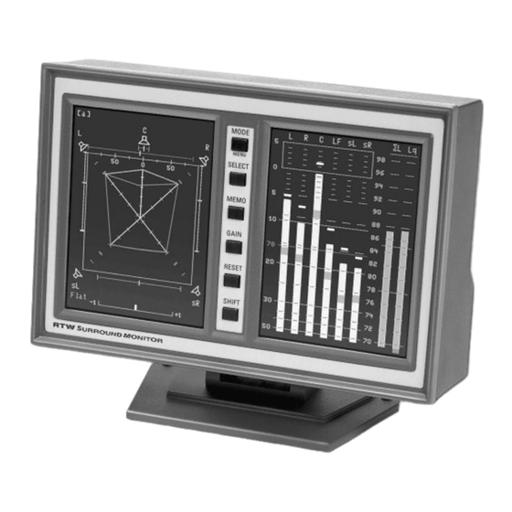
D 2. Funktionsübersicht Instrument-Display: PPM-Display: Instrument- PPM- Display Display Bild D 2-1: Die Anzeigen des SurroundMonitor am Beispiel des 10860X-VID... - Page 20 Bild D 2-2: Surround-Sound-Analyzer (linkes Display)
- Page 21 Bild D 2-3: 10-fach Multi-Korrelator im Surround-3/2 (5.1)-Modus (linkes Display) Bild D 2-4: Vektorskop für Stereo- oder Surround-Signale (linkes Display)
- Page 22 Bild D 2-5: Echtzeit-Spektrum-Analysator (RTA – linkes Display) Bild D 2-6: Dialnorm-Meter (linkes Display)
- Page 23 Bild D 2-7: Vektorskop für externe Stereo- oder Downmix-Signale (linkes Display) Bild D 2-8: AES/EBU-Statusdisplay (linkes Display, Hilfstext im rechten Display)
- Page 24 Bild D 2-9: Multinorm Peakmeter (rechtes Display)
-
Page 25: D 3. Schnellstart
D 3. Schnellstart... - Page 26 Menü-Anzeige: Beschriftung: Tasten: Hilfe-Anzeige: Bild 3-1: Das Hauptmenü (Main Menu) der SurroundMonitor 10800X Serie am Bei- spiel des 10860X-VID...
- Page 29 : s i ö ä r , t r ) - t ä r x i f ä i g i l a t i g i l a t i g i l a t i g i l a t : t r u l l Ä...
-
Page 35: D 4. Anzeigearten
D 4. Anzeigearten Bild D 4-1: Peakmeter-Anzeige im rechten TFT-Display Σ... - Page 36 Bild D 4-2: Numerische Anzeige im linken TFT-Display mit gedrückter Taste MEMO...
- Page 37 Bild D 4-3: Mode-Setup-Menü im linken TFT-Display im 3/2 (5.1)-Surround-Modus...
- Page 39 Bild D 4-4: Der Surround-Sound-Analyzer im 3/2 (5.1)-Modus im linken TFT-Display Bild D 4-5: Der Surround-Sound-Analyzer im 3/1-Modus im linken TFT-Display...
- Page 42 Bild D 4-6: Anzeigebeispiele des Instrumentes „Surround Sound Analyzer” (siehe auch: www.rtw.de/special/index.html)
- Page 43 Σ Σ...
- Page 45 Bild D 4-7: Die Multi-Korrelator-Anzeige im 3/2 (5.1)-Modus im linken TFT-Display...
- Page 46 Bild D 4-8: Der Multi-Korrelator im 3/1-Modus (links) und 8-Kanal-Modus (rechts) Σ Σ...
- Page 48 Bild D 4-9: Die Vektorskop-Anzeige im linken TFT-Display (3/2 (5.1)-Surround-Modus)
- Page 50 Bild D 4-10: Die RTA-Anzeige im linken TFT-Display...
- Page 52 Bild D 4-11: Die Dialnorm-Anzeige im linken TFT-Display mit Anzeige des gewählten Kanals im rechten TFT-Display...
- Page 57 Bild D 4-12: Die VSC-L*R*-Anzeige für externe Signale im linken TFT-Display...
- Page 58 Bild D 4-13: Die AES/EBU-Statusmonitor-Anzeige im linken TFT-Display...
- Page 59 bild D 4-14: Die verschiedenen Anzeigearten des AES/EBU-Statusmonitor...
-
Page 61: D 5. Funktionstasten
D 5. Funktionstasten Bild D 5-1: Die Funktionstasten des SurroundMonitor am Beispiel des 10860X-VID Bild D 5-2: Beispiele verschiedener Tastenfunktionen, abhängig von der Betriebsart... - Page 62 : ) l – – – – – – – – – – – – – – – i t l – – –...
-
Page 65: Übersicht Über Die Menüstruktur
Überblick über die Menüstruktur... -
Page 67: D 6. Menü
D 6. Menü Bild D 6-1: Das Hauptmenü des SurroundMonitor am Beispiel des 10860X-VID... - Page 68 Bild D 6-2: Hardware-Status-Anzeige...
- Page 69 ...
-
Page 70: D 6.3.4.1. Mode-Setup Für 2-Kanal-Betriebsarten
Bild D 6-3: Mode-Setup-Menü für die 2-Kanal-Betriebsart... -
Page 73: D 6.3.4.2. Mode-Setup Für 8-Kanalbetriebsarten
Bild D 6-4: Mode-Setup-Menü für die 8-Kanal-Betriebsart... -
Page 76: D 6.3.4.3. Mode-Setup Für Surround 3/1-Betriebsarten
Σ... - Page 77 Bild D 6-5: Mode-Setup-Menü für die 3/1-Surround-Betriebsart...
-
Page 80: D 6.3.4.4. Mode-Setup Für Surround 3/2 (5.1)-Betriebsarten
Σ Bild D 6-6: Mode-Setup-Menü für die 3/2 (5.1)-Surround-Betriebsart... - Page 83 ...
- Page 84 ...
- Page 85 ...
- Page 86 ...
- Page 87 ↓ ↓ ↑...
- Page 88 Ω Ω ↑ Ω ...
- Page 89 Bild D 6-7: Tastenfunktionen im Dialnorm-Modus (links) und im Dialnorm-Setup- Menü (rechts)
-
Page 91: D 7. Installation
D 7. Installation... - Page 92 Bild D 7-1: Anschlusspanel auf der Geräterückseite am Beispiel des 10800X-PLUS...
- Page 94 P i n 1 P i n 1 4 P i n 2 P i n 1 5 P i n 3 P i n 1 6 P i n 4 P i n 1 7 P i n 5 P i n 1 8 P i n 6 P i n 1 9...
- Page 95 Ω P i n 1 P i n 1 4 P i n 2 P i n 1 5 P i n 3 P i n 1 6 P i n 4 P i n 1 7 P i n 5 P i n 1 8 P i n 6 P i n 1 9...
- Page 96 (Außenansicht Einbaubuchse) Pin 3 Pin 2 +24 V DC ±10 % Pin 4 Pin 1 +24 V DC = 920 mA nom.
- Page 97 Ω Ω ↓ Ω (Außenansicht Einbaubuchse)
- Page 98 (Außenansicht der Einbaubuchse)
- Page 99 Pegel Kanal 8 Pegel Kanal 7 Pegel Kanal 6 Pegel Kanal 5 Pegel Kanal 4 Pegel Kanal 3 Pegel Kanal 2 Pegel Kanal 1 CASE4 CASE2 CASE2 P100 P120 P140 P160 P181 P201 P221 P241 TP26 TP21 TP23 TP24 TP22 TP25 P101 P121...
-
Page 101: D 8. Service
D 8. Service... - Page 102 Bild D 8-1: Entfernen der Abdeckung auf der Rückseite...
- Page 103 Bild D 8-2: Lösen der Hauptplatine und er Anschlussplatte...
- Page 104 Bild D 8-3: Lösen der Flachbandkabel Bild D 8-4: Entfernen der Einheit aus Hauptplatine und Anschlussplatte...
- Page 105 Bild D 8-5: Lösen der Flachbandkabel an der Displayeinheit Bild D 8-6: Entfernen des Tastenprints...
- Page 106 Bild D 8-7: Einbau des Tastenprints in die neue Displayeinheit Bild D 8-8: Befestigen der Flachbandkabel an der neuen Displayeinheit...
- Page 107 Bild D 8-9: Anschlüsse an die locker eingesetzte Hauptplatine Bild D 8-10: Befestigen der Hauptplatine...
- Page 108 Bild D 8-11: Befestigen des Abdeckblechs...
- Page 109 Bild D 8-12 : Entfernen des Abdeckblechs auf der Rückseite...
- Page 110 Bild D 8-13 : Lösen der Einheit aus Hauptplatine und Anschlussplatte...
- Page 111 Bild D 8-14 : Lösen der Flachbandkabel und Entfernen der Einheit aus Haupt- platine und Anschlussplatte...
- Page 112 Bild D 8-15 : Lösen der Flachbandkabel am Display Bild D 8-16 : Entfernen des Tastenprints...
- Page 113 Bild D 8-17 : Entfernung des Silikons und Entnahme des defekten Displays Bild D 8-18 : Einsetzen und Fixieren des neuen Displays...
- Page 114 Bild D 8-19 : Einsetzen des Tastenprints Bild D 8-20 : Befestigen der Flachbandkabel am Display...
- Page 115 Bild D 8-21: Einsetzen der Einheit aus Anschlussplatte und Hauptplatine Bild D 8-22: Befestigen der Einheit aus Anschlussplatte und Hauptplatine...
- Page 116 Bild D 8-23: Befestigen des hinteren Abdeckbleches...
- Page 117 Bild D 8-24: Entfernen der Abdeckung auf der Rückseite...
- Page 118 Bild D 8-25: Herausziehen der Lochbleche...
- Page 119 Klemmverriegelung Clamping lock Bild D 8-26 Lösen von Verbindungs- und Flachbandkabeln...
- Page 120 Bild D 8-27: Lösen der Frontblende und Herunterkippen auf die Unterlage Bild D 8-28: Lösen und Entfernen des defekten Displays...
- Page 121 Bild D 8-29: Montieren des neuen Displays Bild D 8-30: Montieren der Frontblende...
- Page 122 Klemmverriegelung Clamping lock Bild D 8-31: Anschließen der Verbindungs- und Flachbandkabel Bild D 8-32: Einschieben der Lochbleche...
- Page 123 Bild D 8-33: Befestigen der Abdeckung auf der Rückseite...
-
Page 125: D 9. Mechanisches Layout Und Ersatzteile
D 9. Mechanisches Layout und Ersatzteile... - Page 130 1169-R 1175-R 1167 1186 13715 13710 (Instrument nicht enthalten)
- Page 131 1175-R 1169-R 10810-203 z. B. für Studer-Mischpulte 10820-203 z. B. für Lawo-Mischpulte 10830-218 z. B. für SSL-Mischpulte 1186 1167...
- Page 132 1175-R 1169-R 1167 1186...
- Page 135 4 x 16139 4 x 16139 164736 2 x 164738 2 x 164738 2 x 16047 2 x 16047 2 x 163364 2 x 163364 4 x 161801 4 x 161801 129839 165592 164736 164739 137939 160568 160568 2 x 144475 2 x 144475 160565 160565...
- Page 139 Anhang A: Technische Daten Ω Ω...
- Page 145 EN 61000-4-5:2007-08 EN 61000-4-6+A1:2002-02 EN 61000-4-11:2005-04 Sicherheit 2006/95/EG DIN IEC 61010 (VDE 0411 Teil 1): 2004 Geprüft und dokumentiert von nachfolgend aufgeführten Firmen: SERCO GmbH, Bonn, akkreditiertes Prüflabor RTW GmbH & Co. KG, Köln Datum und Unterschrift des Verantwortlichen: 28.10.2007...
- Page 147 Anhang C: Index (deutsch) Symbole...
- Page 149 Operating Manual english...
- Page 151 E 1 Before you begin Fig. E 1-1: SurroundMonitor 10800X-PLUS (10809X-PLUS) Fig. E 1-2: SurroundMonitor 10810-203 (10820-203, 10830-218) Fig. E 1-3: SurroundMonitor 10860X-VID...
- Page 153 ...
- Page 159 E 2 Key Features Instrument Display: PPM Display: Instrument Display Display Fig. E 2-1: The displays of the SurroundMonitor (Example: 10860X-VID)
- Page 160 Fig. E 2-2: Surround Sound Analyzer (left display) Fig. E 2-3: 10-fold Multi-Correlator in surround 3/2 (5.1) mode (left display)
- Page 161 Fig. E 2-4: Vectorscope for stereo or surround signals (left display) Fig. E 2-5: Real time spectrum analyzer (RTA – left display)
- Page 162 Fig. E 2-6: Dialnorm meter (left display) Fig. E 2-7: Vectorscope for external stereo or downmix signals (left display)
- Page 163 Fig. E 2-8: AES/EBU status display (left display, help informations on the right display) Fig. E 2-9: Multi-standard peakmeter (right display)
- Page 165 E 3 Quick Start...
- Page 166 Menu display: Captions: Buttons: Help display: Fig. E 3-1: The Main Menu of the SurroundMonitor 10860X-VID...
- Page 169 e i f ! x i : s t i g i l a t i g i l a t i g i l a t i g i l a t – – – – i t l t a l –...
- Page 173 E 4 Display Modes Fig. E 4-1: Peak program meter display on the right TFT-display Σ...
- Page 174 Fig. E 4-2: Numerical display on the left TFT-display with MEMO button pressed...
- Page 175 Fig. E 4-3: Mode-Setup menu display on the left TFT-display in 3/2 (5.1) surround mode...
- Page 177 Fig. E 4-4: The Surround Sound Analyzer display in 3/2 (5.1) mode on the left TFT-display Fig. E 4-5: The Surround Sound Analyzer display in 3/1 mode on the left TFT-display...
- Page 179 Fig. E 4-6: Examples of displays in the Surround Sound Analyzer instrument (SSA) in 3/2 (5.1) surround mode, also see: www.rtw.de/english/special/index.html...
- Page 180 Σ Σ...
- Page 182 Fig. E 4-7: The Multi Correlator display in 3/2 (5.1) mode on the left TFT-display...
- Page 183 Fig. E 4-8: The Multi Correlator display in 3/1 mode (left) and 8-channel mode (right) Σ Σ...
- Page 185 Fig. E 4-9: The vectorscope display in 3/2 (5.1) surround mode on the left TFT display...
- Page 187 Fig. E 4-10: The RTA display on the left TFT display...
- Page 189 Fig. E 4-11: The Dialnorm display on the left TFT display with the display of the selected channel on the right TFT display...
- Page 193 Fig. E 4-12: The VSC L*R* display for external signals on the left TFT display...
- Page 194 Fig. E 4-13: The AES/EBU status monitor display on the left TFT display...
- Page 195 Fig. E 4-14: The different modes of the AES/EBU Status display...
- Page 197 E 5 Function Keys Fig. E 5-1: The function keys of the SurroundMonitor (Example: 10860X-VID) Fig. E 5-2: Examples for different key functions depending on the operating mode...
- Page 198 : ) l – – – – – – – – – – – – – – – - i t – – –...
- Page 201 Overview of Menu Structure...
- Page 203 E 6 Menu Fig. E 6-1: The Main menu of the SurroundMonitor (Example: 10860X-VID)
- Page 204 Fig. E 6-2: Hardware status screen...
- Page 205 ...
- Page 206 Fig. E 6-3: Mode Setup menu for 2-Channel mode...
- Page 209 Fig. E 6-4: Mode Setup menu for 8-Channel mode...
- Page 212 Σ...
- Page 213 Fig. E 6-5: Mode Setup menu for 3/1 surround mode...
- Page 216 Σ Fig. E 6-6: Mode Setup menu for 3/2 (5.1) surround mode...
- Page 219 ...
- Page 220 ...
- Page 221 ...
- Page 222 ...
- Page 223 ↓ ↓ ↑...
- Page 224 Ω Ω Ω ...
- Page 225 Fig. E 6-7: Key functions of Dialnorm mode (left) and Dialnorm setup menu (right)
- Page 227 E 7 Installation...
- Page 228 mounts as a half-19-inch rack-mountable module into standard 19“ installation racks and can be mounted right next to waveform monitors Fig. E 7-1: Connector panel on the rear side of the unit...
- Page 230 P i n 1 P i n 1 4 P i n 2 P i n 1 5 P i n 3 P i n 1 6 P i n 4 P i n 1 7 P i n 5 P i n 1 8 P i n 6 P i n 1 9...
- Page 231 Ω P i n 1 P i n 1 4 P i n 2 P i n 1 5 P i n 3 P i n 1 6 P i n 4 P i n 1 7 P i n 5 P i n 1 8 P i n 6 P i n 1 9...
- Page 232 External view of the connector Pin 3 Pin 2 +24 V DC ±10 % Pin 4 Pin 1 +24 V DC = 920 mA nom.
- Page 233 Ω Ω ↑ Ω External view of the connector...
- Page 234 (External view of the connector)
- Page 235 Pegel Kanal 8 Pegel Kanal 7 Pegel Kanal 6 Pegel Kanal 5 Pegel Kanal 4 Pegel Kanal 3 Pegel Kanal 2 Pegel Kanal 1 CASE4 CASE2 P100 P120 P140 P160 P181 P201 P221 P241 TP26 TP21 TP23 TP24 TP22 TP25 P101 P121 P141...
- Page 237 E 8 Service...
- Page 238 Fig. E 8-1: Remove rear cover...
- Page 239 Fig. E 8-2: Loosen the mounting unit with main pcb and connector panel...
- Page 240 Fig. E 8-3: Loosen the flat cables Fig. E 8-4: Removing the mounting unit with main pcb and connector panel...
- Page 241 Fig. E 8-5: Removing the flat cable from the display Fig. E 8-6: Removing the switch pcb...
- Page 242 Fig. E 8-7: Installation of switch pcb to the new display unit Fig. E 8-8: Connecting the flat cables to the new display unit...
- Page 243 Fig. E 8-9: Connecting main pcb Fig. E 8-10: Fastening main pcb and connector panel...
- Page 244 Fig. E 8-11: Mounting of rear cover...
- Page 245 Fig. E 8-12: Remove rear cover...
- Page 246 Fig. E 8-13: Loosening the mounting unit of main pcb and connector panel...
- Page 247 Fig. E 8-14: Loosening flat cables and removing mounting unit of main pcb and connector panel...
- Page 248 Fig. E 8-15: Removal of the flat cable from the display unit Fig. E 8-16: Removal of switch pcb...
- Page 249 Fig. E 8-17: Disassembling a broken display (removing silicone) Fig. E 8-18: Assembling the new display unit...
- Page 250 Fig. E 8-19: Mounting of switch pcb Fig. E 8-20: Connecting the flat cables to the display...
- Page 251 Fig. E 8-21: Replacing the mounting unit of main pcb and connector panel Fig. E 8-22: Fastening the mounting unit of main pcb and connector panel...
- Page 252 Fig. E 8-23: Reinstalling the rear cover...
- Page 253 Fig. E 8-24: Removing the rear cover panel...
- Page 254 Fig. E 8-25: Removing the perforated cover metal plates...
- Page 255 Klemmverriegelung Clamping lock Fig. E 8-26 Removing connecting cables and data cables...
- Page 256 Fig. E 8-27: Removing and upending the front panel Fig. E 8-28: Lösen und Entfernen des defekten Displays...
- Page 257 Fig. E 8-29: Mounting the new display Fig. E 8-30: Mounting the front panel...
- Page 258 Klemmverriegelung Clamping lock Fig. E 8-31: Reconnecting the connecting cables and the data cables Fig. E 8-32: Moving back the perforated cover metal plates...
- Page 259 Fig. E 8-33: Befestigen der Abdeckung auf der Rückseite...
- Page 261 E 9 Mechanical Layout and Spare Parts...
- Page 266 1169-R 1175-R 1167 1186 13715 13710 (Instrument not included)
- Page 267 1175-R 1169-R 10810-203 e. g. for Studer consoles 10820-203 e. g. for Lawo consoles 10830-218 e. g. for SSL consoles 1186 1167...
- Page 268 1175-R 1169-R 1167 1186...
- Page 271 4 x 16139 4 x 16139 164736 2 x 164738 2 x 164738 2 x 16047 2 x 16047 2 x 163364 2 x 163364 4 x 161801 4 x 161801 129839 165592 164736 164739 137939 160568 160568 2 x 144475 2 x 144475 160565 160565...
- Page 275 Appendix A: Specifications Ω Ω...
- Page 281 EN 61000-4-6+A1:2002-02 EN 61000-4-11:2005-04 Safety 2006/95/EEC DIN IEC 61010 (VDE 0411 Teil 1): 2004 Tested and documented by the following companies: SERCO GmbH, Bonn, accredited EMC laboratory RTW GmbH & Co. KG, Köln Date and signature of the responsible person: 2007-10-28...
- Page 283 Appendix C: Index (english)
- Page 285 << zurück...
- Page 286 << back...
Need help?
Do you have a question about the SurroundMonitor 10800X Series and is the answer not in the manual?
Questions and answers