Table of Contents
Advertisement
Available languages
Available languages
Quick Links
Advertisement
Chapters
Table of Contents

Related Manuals for RTW TouchMonitor TM3 Smart


Summary of Contents for RTW TouchMonitor TM3 Smart
- Page 1 TouchMonitor TM3 Smart Manual...
- Page 2 TouchMonitor TM3 Smart Software Version 5.02 | 04.2019 • TM3 Smart (TM3S) © 2019 | RTW GmbH & Co.KG Am Wassermann 25 | 50829 Köln | Germany Phone +49 221. 70 913-0 | Fax +49 221. 70 913-32 www.rtw.com | rtw@rtw.com...
- Page 3 TouchMonitor TM3 Smart Bedienungsanleitung...
- Page 4 Software-Version: 5.02 und höher | 04.2019 © 2019 | Technische Änderungen vorbehalten! RTW GmbH & Co.KG | Am Wassermann 25 | 50829 Köln | Germany Phone +49 221. 70 913-0 | Fax +49 221. 70 913-32 www.rtw.com | rtw@rtw.com WEEE-Reg.-Nr.: DE 90666819 RoHS-Konformität: Diese Geräte erfüllen als Überwachungs- und Kon-...
-
Page 5: Sicherheitshinweise
Sicherheitshinweise Die folgenden Symbole sind auf dem Gehäuse des Gerätes, auf einzel- nen Modulen und in dieser Bedienungsanleitung zu fi nden: WARNUNG! Dieses Symbol warnt Sie vor einer möglicherweise gefährlichen Situation, etwa vor gefährlichen Spannungen, die Sie einem elektrischen Schock aussetzen könnten. -
Page 6: Allgemeine Sicherheitsanweisungen
Personal durchgeführt werden. • Entfernen Sie keine Teile aus dem Gerät und führen Sie keine Modifi - kation am Gerät aus ohne die schriftliche Freigabe durch RTW. Verän- derungen am Gerät können sowohl Sicherheitsrisiken verursachen als auch die Konformitäten und Zertifi... - Page 7 • Verwenden Sie nur geeignete Netzkabel bzw. Netzgeräte. Verwenden Sie ausschließlich Netzkabel und Netzteile, die für dieses Gerät freige- geben und in Ihrem Land zertifi ziert sind. • Beachten Sie alle Anschlusswerte und Markierungen auf dem Gerät. Informieren Sie sich in der Bedienungsanleitung über weitere Details zu den Anschlusswerten, bevor Sie etwas anschließen.
-
Page 8: Achtung
ACHTUNG! Folgen Sie immer den Sicherheitsmaßnahmen, um Verletzungen oder Beschädigungen am Gerät oder anderen Objekten zu vermeiden. Diese Maßnahmen beinhalten die folgenden Punkte, sind aber nicht auf diese beschränkt: • Blockieren Sie keine Lüftungsöffnungen. Installieren Sie das Gerät ent- sprechend der Anweisungen zur Sicherstellung einer adäquaten Belüf- tung, um einen zu hohen Temperaturanstieg im Inneren zu vermeiden. -
Page 9: Umweltschutz
Umweltschutz Beachten Sie die folgenden Informationen zur Umweltverträglichkeit des Gerätes und die Hinweise, wenn Sie ein Gerät oder Bauteile recyceln möchten (Handhabung am Ende der Produktlebensdauer): • Wiederverwertung des Gerätes Bei der Herstellung dieses Gerätes wurden natürliche Ressourcen einge- setzt und verbraucht. Das Gerät kann Substanzen beinhalten, die bei un- sachgemäßer Entsorgung schädlich für Umwelt oder für Menschen sein könnten. -
Page 10: Table Of Contents
Inhalt Sicherheitshinweise 5 | Instrumente Allgemeine Sicherheitsanweisun- 5.1 | Program Meter 5.2 | Loudness Sum Warnung! 5.3 | LRA Achtung! 5.4 | Loudness Num Umweltschutz 5.5 | Correlator 5.6 | Global Keyboard Inhalt 5.7 | Dialnorm 5.8 | AES-Status 1 | Bevor Sie beginnen 5.9 | Moving Coil 1.1 | Das Konzept 5.10 | Timecode Reader... -
Page 11: Bevor Sie Beginnen
1 | Bevor Sie beginnen 1.1 | Das Konzept Vielen Dank für den Erwerb eines TouchMonitor TM3 Smart (TM3S) von RTW. Sie haben sich für eine leistungsfähige Metering-Lösung auf der Basis moderner Hardware und aktuellster Technologie entschieden, die eine sehr intuitive, voraussetzungsfreie Bedienung im Bedarfsfall mit hoher Flexibilität und weit reichenden Konfi... - Page 12 Als autarkes Gerät mit eleganter Touchscreen-Presetsteuerung stellt Ihnen der TouchMonitor TM3 Smart immer genau die Informationen über die gemessenen Audiosignale zur Verfügung, die Sie für eine schnelle und sichere Interpretation auch ohne tiefgreifendes technisches Hintergrundwissen benötigen. Der vertikal oder horizontal nutzbare, kontrastreiche 4,3“-Bildschirm unterstützt Sie dabei jederzeit mit einer...
- Page 13 Bei der Konfi guration der in den Geräten gespeicherten Presets mit Hilfe der Software-Anwendung Devicer DC1 (kompatibel zu Windows® & Mac OS X®) zeigt der TouchMonitor TM3 Smart seine ganze Leistungsfähigkeit und Flexibilität. Neben PPM- und True Peak-Instrumenten bieten die TM3-Geräte umfassende Loudness- Messfunktionen nach allen weltweit relevanten Standards ( EBU R128, ITU BS.1770-4/1771-1, ARIB, ATSC A/85, OP-59, AGCOM,...
-
Page 14: Lieferumfang
Packen Sie das Instrument aus, fi nden Sie unten Ihre Version und prüfen Sie, ob Sie alle entsprechenden Komponenten erhalten haben. Falls Teile fehlen, wenden Sie sich bitte an Ihren Händler. TouchMonitor TM3 Smart (Tischgerät) TM3S > Display-Einheit + Interfacebox >... -
Page 15: Hardware-Option
TM3 Smart mit gleichzeitig bestellter Option TM3-2U TM3S mit > Einbau-Display + Interfacebox > Netzteil > Manual TM3-2U (6-Kanal) > USB-Kabel > Material verbunden zur Montage in TM3-MA2U > Basis-Software (PPM/TruePeak, Loudness, LRA, Korrelator) plus 6-Kanal Moving Coil Timecode Chart 1.3 | Hardware-Option (separat bestellbar) TM3-MA2U... -
Page 16: Installation
2 | Installation Die TouchMonitor TM3 Smart Geräte wurden für die freie Platzierung auf Tischen, Pulten, u. a. entwickelt. Sie bestehen aus einer Display- Einheit mit 4,3-Zoll Touch Screen und einer abgesetzter Interfacebox, die über vielfältige Anschlussmöglichkeiten verfügt und über ein Kabel die Display-Einheit mit Daten und Strom versorgt. -
Page 17: Anschlüsse
2.1 | Anschlüsse Frontansicht der Interface-Box Potis zur Einstellung der Eingangs- empfi ndlichkeit GP IO (150 mV - 30 V) (RJ-12-6P6C) S/PDIF Out Analog In L (RCA) (RCA) *) S/PDIF In Analog In R (RCA) (RCA) *) *) Analog In über RCA und Analog In über Sub-D können nicht parallel benutzt werden! - Page 18 Anschlüsse (Fortsetzung) Linke Seitenansicht der Interface-Box Analog In L/R (Sub-D) *) 3 AES3 In/Out (1 - 3, Sub-D) *) Analog In über Sub-D und Analog In über RCA können nicht parallel benutzt werden! Rechte Seitenansicht der Interface-Box Gesteckte Verbindung zur Display-Einheit (2 m, max.
-
Page 19: Pin-Belegung
2.2 | Pin-Belegung „Analog In L“, „Analog In R“ (unsymmetrisch, RCA-F) Pin: Funktion: Signal Ring Ring Schirm/Gehäuse (Außenansicht der Einbaubuchse) HINWEIS - Die Eingangsempfi ndlichkeit ist einstellbar im Be- reich von 150 mV bis 30 V. Bei Verwendung der RCA-Buchsen können die entsprechenden Eingän- ge der Sub-D-Anschlussleiste nicht verwendet werden. - Page 20 Pin-Belegung (Fortsetzung) „Anschlussleiste Sub-D“ (25-pol. Sub-D-F) Pin: Funktion: Eingang Analog R (+, heiß) P i n 1 P i n 1 4 Eingang Analog R (–, kalt) Paar 8 P i n 2 P i n 1 5 P i n 3 Schirm/Gehäuse P i n 1 6 P i n 4...
- Page 21 Pin-Belegung (Fortsetzung) „GPIO“ (RJ-12-6P6C-Buchse) Externe Steuerung der im Menü „Globales Tastenfeld“ defi nierten Funkti- onen oder Presets. Die als „active low“ ausgelegten Eingänge sind gegen 0 V (Pin 1) zu schalten. Pin: Funktion: 2 - 6 Funktion entsprechend der Defi nition im Menü (Außenansicht der Einbaubuchse) „24 V DC“...
-
Page 22: Bedienung
Box an. Benutzen Sie das zum Lieferumfang des TM3S gehörende Netzteil RTW 1178-R. • Verbinden Sie das Netzteil mit dem Stromnetz. Nach kurzer Zeit ist der TouchMonitor TM3 Smart betriebsbereit. Manual | TM3S DE-20 3 | Bedienung | 3.1 | Inbetriebnahme... -
Page 23: Signalquellen Und Synchronisation
3.2 | Signalquellen und Synchronisation Der TM3S besitzt mehrere Eingänge für analoge und digitale Signal- quellen. Diese sind im Kapitel 2 | Installation im Detail beschrieben. Die Auswahl des aktiven Signaleingangs für die aktuelle Messung erfolgt durch das Laden eines passenden Presets. Deshalb ist es möglich, durch einfaches Laden eines neuen Presets sehr elegant zwischen mehreren gleichzeitig angeschlossenen Signalquellen umzuschalten. - Page 24 Analogeingang ist jedoch nicht möglich. Synchronisation auf digitale Signalquellen Der TouchMonitor TM3 Smart verarbeitet an seinen vier Digitaleingängen (S/PDIF und AES3) digitale Signalquellen mit Abtastraten bis zu 96 kHz. Falls digitale Signalquellen im AES3-Format genutzt werden sollen, muss am ersten AES3-Eingang stets ein digitales Eingangssignal zur Synchro- nisation anliegen –...
-
Page 25: Vertikale Und Horizontale Presets Laden
3.3 | Vertikale und horizontale Presets laden Die Display-Einheit des TouchMonitor TM3 Smart kann sowohl vertikal als auch horizontal aufgestellt werden. Für beide Ausrichtungen sind im Gerät passende Preset-Versionen gespeichert. Vertikale Ausrichtung Um den TM3S im vertikalen Anzeigemodus zu nutzen, bringen Sie die Display-Einheit einfach in die aufrechte Position. - Page 26 Horizontale Ausrichtung Um den TM3S im horizontalen Anzeigemodus zu nutzen, kippen Sie die Display-Einheit nach links, so dass sich der Fuß auf der rechten Seite befi ndet. • Wischen Sie mit einem Finger in beliebiger Richtung horizontal über den Bildschirm, um durch die gespeicherten Presets für den Horizon- talbetrieb zu blättern.
-
Page 27: Presets
4 | Presets Die TouchMonitor TM3 Smart Geräte enthalten im Auslieferungszustand Werks-Presets, die einen Querschnitt durch die unterstützten Anwen- dungsgebiete, Anschlussformate und Standards darstellen. Mit Hilfe dieser Presets können Sie die Geräte unmittelbar in Betrieb nehmen - auch ohne Anschluss an einen Computer und Installation der Konfi gura- tions-Software Devicer DC1. - Page 28 Im folgenden Abschnitt sind die wichtigsten Merkmale der gespeicherten Werks-Presets aufgelistet. Dazu gehören auch die vom jeweiligen Preset angesprochenen Eingangsbuchsen. Nähere Details zu den Audio-Eingän- gen der TM3S-Geräte und zur Pin-Belegung des Sub-D-Steckverbinders fi nden Sie im Kapitel 2 | Installation. HINWEIS - Presets mit der Eingangszuordnung Analog sind bei Verwendung der beiden symmetrischen Analogeingänge (Sub-D-Buchse) auf den in der Preset-Beschreibung genannten Bezugspegel (+6 dBu)
- Page 29 2CH ANALOG PPM DIN Eingang: Analog L, Analog R Bezugspegel: +6 dBu für „0 dB“ (Eingangskalibrierung +6 dBu) Program Meter-Skala: DIN5 Instrumente: Program Meter, Correlator Manual | TM3S 4 | Presets DE-27...
- Page 30 2CH ANALOG PPM BRIIA Eingang: Analog L, Analog R Bezugspegel: +8 dBu für „6“ (Eingangskalibrierung +6 dBu) Program Meter-Skala: British IIa Instrumente: Program Meter, Correlator Manual | TM3S DE-28 4 | Presets...
- Page 31 2CH AES EBU TP LOUDNESS Eingang: AES3 1 Program Meter-Skala: TP60 Loudness-Standard: EBU R128 Instrumente: Program Meter, LRA, Loudness Num Tasten: Loudness Start, Stop, Reset Manual | TM3S 4 | Presets DE-29...
- Page 32 2CH AES EBU SUM LOUDNESS Eingang: AES3 1 Loudness-Standard: EBU R128 Instrumente: Loudness Sum, LRA, Loudness Num Tasten: Loudness Start, Stop, Reset Manual | TM3S DE-30 4 | Presets...
- Page 33 3 X 2CH EBU LOUDNESS Eingang: AES3 1, AES3 2, AES3 3 Loudness-Standard: EBU R128 Instrumente: 3 x Loudness Sum, 3 x Loudness Num Tasten: Loudness Start, Stop, Reset (pro Kanalpaar) Manual | TM3S 4 | Presets DE-31...
- Page 34 5.1 AES EBU TP LOUDNESS Eingang: AES3 1, AES3 2, AES3 3 Program Meter-Skala: TP60 Loudness-Standard: EBU R128 Instrumente: Program Meter, Loudness Num Tasten: Loudness Start, Stop, Reset Manual | TM3S DE-32 4 | Presets...
- Page 35 2CH SPDIF EBU TP LOUDNESS Eingang: S/PDIF Program Meter-Skala: TP60 Loudness-Standard: EBU R128 Instrumente: Program Meter, Correlator, LRA, Loudness Sum, Loudness Num Tasten: Loudness Start, Stop, Reset Manual | TM3S 4 | Presets DE-33...
- Page 36 2CH AES ATSC TP LOUDNESS Eingang: AES3 1 Program Meter-Skala: TP60 Loudness-Standard: ATSC A/85 Instrumente: Program Meter, LRA, Loudness Num Tasten: Loudness Start, Stop, Reset Manual | TM3S DE-34 4 | Presets...
- Page 37 2CH AES ATSC SUM LOUDNESS Eingang: AES3 1 Loudness-Standard: ATSC A/85 Instrumente: Loudness Sum, LRA, Loudness Num Tasten: Loudness Start, Stop, Reset Manual | TM3S 4 | Presets DE-35...
- Page 38 3 X 2CH ATSC LOUDNESS Eingang: AES3 1, AES3 2, AES3 3 Loudness-Standard: ATSC A/85 Instrumente: 3 x Loudness Sum, 3x Loudness Num Tasten: Loudness Start, Stop, Reset (pro Kanalpaar) Manual | TM3S DE-36 4 | Presets...
- Page 39 5.1 AES ATSC TP LOUDNESS Eingang: AES3 1, AES3 2, AES3 3 Program Meter-Skala: TP60 Loudness-Standard: ATSC A/85 Instrumente: Program Meter, Loudness Num Tasten: Loudness Start, Stop, Reset Manual | TM3S 4 | Presets DE-37...
- Page 40 2CH SPDIF ATSC TP LOUDNESS Eingang: S/PDIF Program Meter-Skala: TP60 Loudness-Standard: ATSC A/85 Instrumente: Program Meter, Correlator, LRA, Loudness Sum, Loudness Num Tasten: Loudness Start, Stop, Reset Manual | TM3S DE-38 4 | Presets...
-
Page 41: Instrumente
5 | Instrumente In den TouchMonitor TM3 Smart Geräten stehen die nachfolgend be- schriebenen Instrumente zur Verfügung, die jeweils unterschiedliche Parameter der gemessenen Audiosignale visualisieren. Die meisten dieser Instrumente wurden in den Werks-Presets auf verschiedene Weise miteinander kombiniert. Verwenden Sie bitte die Konfi gurations-Software Devicer DC1, um die Instrumenten-Auswahl oder die Bildschirmauftei- lung eines Presets zu verändern oder eigene Presets zu erstellen. -
Page 42: Program Meter
5.1 | Program Meter Signalpegel Loudness Beispiel: Program Meter des TM3 Smart mit kom- binierter Pegel- und Loudness-Anzeige Das Program Meter bietet eine vertikale oder horizontale Bargraph- Anzeige für die Einzelkanäle der aktiven Signalquelle. Das Instrument zeigt pro Kanal entweder den Signalpegel, die Loudness oder eine Kom- bination aus beiden an. - Page 43 Die in den Werks-Presets in Gelb dargestellten Signalpegel können je nach Konfi guration des Presets nach zwei unterschiedlichen Verfahren angezeigt werden. Sie stehen für jeden Einzelkanal wahlweise als tradi- tionelle Quasi-Peakmeter (PPMs) mit verschiedenen wählbaren Skalen (DIN, British, Nordic etc.) oder aber mit der nach aktuellen Standards neu eingeführten True Peak-Skala zur Verfügung.
-
Page 44: Loudness Sum
5.2 | Loudness Sum Skalenmarke Toleranz- für den bereich Target Level Momentary- Shortterm- Bargraph M Bargraph S Beispiel: Loudness Sum-Instrument im EBU-Modus zeigt Momentary-Bargraph und Shortterm-Bargraph S. Der Integrated-Bargraph I ist ausgeblendet. Das Loudness Sum-Instrument gibt die aus allen Einzelkanälen eines Signals kombinierte Gesamt-Loudness mit bis zu drei Bargraphen an, die Messungen mit unterschiedlichen Zeitkonstanten repräsentieren. - Page 45 Die drei im Loudness Sum-Instrument darstellbaren Bargraphen zeigen: • M (Momentary): Summierung der Momentary-Loudnessmessungen in den Einzelkanälen mit einer Integrationszeit von 400 • S (Shortterm): Summierte Loudness-Messung mit einer Integrati- onszeit von 3 s mit gleitendem Fenster. • I (Integrated): Gesamt-Loudness des Programms zwischen einem manuell gesetzten Anfangs- und Endpunkt.
-
Page 46: Lra
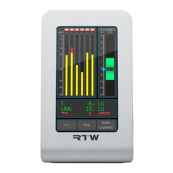
5.3 | LRA Skalenmarke für den Target Level LRA-Low-Range-Bereich Numerischer LRA-Wert Aktueller Integrated-Wert I LRA-Comfort-Zone-Bereich Integrated-Bargraph I LRA-High-Range-Bereich Beispiel: LRA-Instrument im „MagicLRA + I + Num“-Modus mit Integrated-Bargraph (I) und numerischer Anzeige Das LRA-Instrument bietet eine grafi sche Darstellung der Loudness Ran- ge (LRA). - Page 47 Für LRA-Messungen existiert in den Loudness-Standards keine einheitli- che Zielgröße. Allerdings werden die drei farblich unterschiedlich markier- ten Bereiche „Comfort Zone“ (mittlere LRA-Werte), „High Range“ (hohe LRA-Werte) und „Low Range“ (niedrige LRA-Werte) unterschieden, in die ein Programm abhängig von seinem gemessenen LRA-Wert eingeordnet werden kann.
-
Page 48: Loudness Num
5.4 | Loudness Num Aktueller Aktueller Momentary- Shortterm- Wert M Wert S Aktueller Aktueller Integrated- LRA-Wert Wert I Maximaler Maximaler True Peak- Momentary- Wert TPmax Wert Mmax Maximaler Messzeit- Shortterm- spanne Wert Smax IDauer Beispiel: Loudness Numeric-Instrument zeigt alle Werte: Momentary (M), Shortterm (S), Integrated (I), LRA, TPmax, Mmax, Smax, IDauer. - Page 49 Das Instrument Loudness Num bietet eine numerische Darstellung der folgenden Loudness-Messwerte: • M (Momentary): Summierung der Momentary-Loudnessmessungen in den Einzelkanälen mit einer Integrationszeit von 400 • S (Shortterm): Summierte Loudness-Messung mit einer Integrati- onszeit von 3 s mit gleitendem Fenster. •...
-
Page 50: Correlator
5.5 | Correlator Negativer Positiver Bereich Bereich (rot) (grün) Beispiel: Korrelation ist zwischen +0,3 bis +0,7 (Vollauschlag bedeutet +1) Der Correlator zeigt die Phasenbeziehungen zwischen den beiden Ka- nälen eines Stereosignals und damit seine Mono-Kompatibilität an. Iden- tische Signale in beiden Kanälen haben die Korrelation +1, vollständig unabhängige Signale eine Korrelation von 0. -
Page 51: Global Keyboard
5.6 | Global Keyboard Beispiel: Start-, Stop- und Reset-Tasten zur globalen Steuerung von Loudness-Instrumenten Das Global Keyboard-Instrument, das nur in der Non-Audio-Gruppe zur Verfügung steht, kann bis zu zehn Tasten enthalten, die sich auf unterschiedliche Weise nutzen lassen. Jede Taste, die auf den Modus „In- strument“... -
Page 52: Dialnorm
5.7 | Dialnorm Aktueller Kanäle Modus für die Messung Status der Messung: Max. Mess- Stopp (gelb) dauer Running (grün) Vergange- ne Mess- Leq(k) als dauer Signal-Pegel bezogen auf 0 dBFS Aktueller Dialnorm- Wert Steuer- tasten Beispiel: Die Kanäle L und R sind gewählt, die Berechnung ist noch nicht gestartet (gelb) Das Dialnorm-Instrument wird zur Berechnung numerischer Dialnorm- Werte aus digitalen Surround-Signalen verwendet. - Page 53 Dies basiert auf der Annahme, dass die empfundene Gesamtlautstärke einer Mischung durch den Bezug auf die Sprache (optimierte Sprachver- ständlichkeit bzw. minimierte Störwirkung durch zu laute Sprache) wegen der festen Lautstärkeverhältnisse zwischen Sprache, Musik und Ge- räuscheffekten innerhalb einer Mischung ermittelt bzw. durch geeignete Maßnahmen beim Empfänger relativ gut konstant gehalten werden kann.
-
Page 54: Aes-Status
5.8 | AES-Status Anzeige von: • Kanal-Status • Binär-Daten • Common (abgebildet) • Audio-Bits • Aktive Bits Funktions- tasten Beispiel: Der Statusmonitor mit der Common-Ansicht Die digitalen Audio-Signale liegen im AES3-Format vor. Im Statusmonitor (AES-Status) werden die darin enthaltenen Status-Bytes als Klartext oder Binärdaten angezeigt. -
Page 55: Moving Coil
5.9 | Moving Coil Beispiel: PPM-Anzeige im Dual-L/R-Modus links neben Dual-M/S- Modus bei horizontaler Ausrichtung des TM3S Das Moving-Coil-Instrument bietet für die realistischen Emulationen von Zeigerinstrumenten verschiedene Modi wie PPM, VU, Loudness oder PPM + Loudness. Abhängig vom gewählten Standard und Modus können die Kanäle L und R eines Stereo-Signals wahlweise in einem einzigen Instrument (Dual-Modus, L/R- oder M/S-Anzeige) oder zwei separaten Zeigerinstrumenten (Stereo-Modus) dargestellt werden. -
Page 56: Timecode Reader
5.10 | Timecode Reader Mit dem Timecode Reader-Instrument kann ein Timecode (LTC) aus externer analoger oder digitaler Quelle angezeigt und genutzt werden. Das Instrument kann nur in der Non-Audio-Gruppe ausgewählt werden. Werks-Presets mit Timecode Reader-Instrument: • Keine Manual | TM3S DE-54 5 | Instrumente | 5.10 | Timecode Reader... -
Page 57: Chart
5.11 | Chart I-Bargraph Ausgewählter Loudness- Beispiel: Wert LU-Skala Einstellbarer Vorgegebene & markierter Toleranz des Toleranz- Target Level bereich Graphische Aktuelle Darstellung Position des des Verlaufs Relative Gate über Zeit im Bezug auf den I-Wert Zeitraster Das Loudness-Chart-Instrument zeichnet den Verlauf der Messung eines wählbaren Loudness-Wertes (TP-, M-, S- oder I-Wert über Zeit) als Linie oder farbige Fläche auf einem Koordinatensystem mit wählbarem Zeitraster. -
Page 58: Firmware-Update
Firmware-Version erhältlich waren. Firmware-Updates (und auch die Konfi gurations-Software Devicer DC1) erhalten Sie im Download- Bereich der RTW-Webseite. HINWEIS - Stellen Sie bei der Verwendung des Devicer DC1 sicher, dass Firmware und Devicer jeweils auf dem aktuellsten Stand sind. - Page 59 Gehen Sie wie folgt vor, wenn Sie ein Firmware-Update durchführen: Schließen Sie den betriebsbereiten TM3 mittels eines handelsübli- chen USB-Interface-Kabels (A auf Mini-B) an den Computer an. Das Computer-System erkennt den TM3 als Laufwerk RTW-TM3. Klicken Sie im Download-Bereich der RTW-Webseite (https://www. rtw.com/de/support/manuals-software.html) unter Audio-Monitore auf die Option, die Ihrem TM3 entspricht.
-
Page 60: Windows
Windows® Das Vorgehen bei Windows®-Systemen zeigen wir anhand des Browsers Microsoft Edge und einem TM3 Smart. Klicken Sie auf den Link zum Update-Packet (Firmware-Version n- nn vom <Datum>, n-n: Version). Das Dialog-Feld für den Download öffnet sich. Manual | TM3 Serie DE-58... - Page 61 ZIP-Datei aus und klicken Sie auf Speichern. Wenn der Vorgang ab- geschlossen ist, kann das Dialogfeld am unteren Rand ohne weitere Aktion geschlossen werden. Entpacken Sie die ZIP-Datei und kopieren Sie die Datei rtw- <Name>-fw-n-n.bin (n-n: Version) (1) in das Hauptverzeichnis des Laufwerks RTW-TM3 (2).
-
Page 62: Mac Os X
Mac OS X® Das Vorgehen bei Mac OS X®-Systemen zeigen wir anhand des Brow- sers Safari und einem TM3 Smart. Klicken Sie auf den Link zum Update-Paket (Firmware-Version n- nn vom <Datum>, n-nn: Version) (1). Das Betriebssystem lädt die Datei sofort in den Downloads-Stapel im Dock (2). Manual | TM3 Serie DE-60... - Page 63 11. Klicken Sie im Dock auf diesen Ordner und öffnen Sie ihn. 12. Kopieren Sie die Update-Datei rtw-<Name>-fw-n-nn.bin (n-nn: Version) in das Hauptverzeichnis des Laufwerks RTW-TM3. Die Firmware-Update-Datei wird jetzt auf den TM3 gespeichert. 13. Fahren Sie mit Schritt 14 fort.
- Page 64 14. Melden Sie nach erfolgtem Kopieren und Speichern den TM3 wie ein USB-Laufwerk ordnungsgemäß vom Computer-System ab! Ziehen Sie erst dann das USB-Kabel vom Computer oder vom TM3 ab! ACHTUNG! - Die Abmeldung vom Computer ist erforder-lich, um eine Beschädigung der kopierten Datei zu vermeiden! 15.
-
Page 65: Technische Daten
7 | Technische Daten System Allgemein Spannungsversorgung: +24 V DC (externe Überstrombegrenzung auf 2 A erfor- derlich!) Stromaufnahme: 160 mA Nennstrom, Einschaltstrom deutlich höher Display: 4,3’’-TFT Touch-Screen 272 x 480 Pixel Anschlüsse: 1 x 4-pol. Kleinspannungsstecker Typ 710 (DC) 1 x USB Mini-B; USB 2.0 Full Speed-Anschluss zum Da- tenaustausch zwischen Device-Confi... - Page 66 Technische Daten (Fortsetzung) Funktionen • Instrumente frei skalierbar und positionierbar • Peakmeter bis 6-Kanal • Loudness-Meter: ITU-R BS.1770-4/1771-1, EBU R128, ATSC A/85, ARIB, OP-59, AGCOM, CALM, anwenderspezifi sch • Messzeitsteuerung • Loudness-Range-Instrument (LRA) • Loudness-Chart-Instrument • Timecode-Reader • SPL-Meter • Stereo-Korrelator •...
- Page 67 Technische Daten (Fortsetzung) Digitale Ein-/Ausgänge 1 digitaler S/PDIF-Eingang, RCA, 75 1 digitaler S/PDIF-Ausgang, RCA 3 AES3-Eingänge, symmetrisch, 110 , Sub-D-F-Einbau- buchse, 25-polig (Ein- und Ausgänge) Abtastraten: 44.1, 48, 96 kHz, Taktanbindung über digitalen Signal- Eingang PPM/True-Peak-Anzeige Allgemein Eingangsquellen: analog und/oder digital Peakmeter: 2-Kanal-Stereo bis 6-Kanal, 5.1 Anzeigen:...
- Page 68 Technische Daten (Fortsetzung) Digitale Peakmeter Wortbreite: 24 Bit Digitale Skalen: • TP60: +3 .. –60 dB • TP20: +3 .. –20 dB • Dig60: 0 .. –60 dB • Dig20: 0 .. –20 dB • Dig0: +18 .. 0 dB •...
- Page 69 Technische Daten (Fortsetzung) Global Keyboard Globales Tastenfeld zur Steuerung defi nierter Funktionen in verschiedenen Instrumenten und zum Preset-Aufruf, ermöglicht auch die externe Steuerung über die GP IO- Schnittstelle Loudness- und SPL-Anzeige EBU-R128-Loudness-Modus ITU-R-BS.1771-Loudness-Modus ATSC-A/85-Loudness-Modus ARIB-Loudness-Modus OP-59-Loudness-Modus AGCOM-Loudness-Modus CALM-Loudness-Modus Anwenderspezifi scher Loudness-Modus Anzeige: •...
- Page 70 Technische Daten (Fortsetzung) • EBU+18a: –5 .. –59 LUFS • EBU0: 0 .. –60 LUFS • ITU+9: +9 .. –18 LU • ITU0: 0 .. –30 LKFS • ATSC0: 0 .. –60 LKFS • ATSC0a: 0 .. –30 LKFS Bewertungsfi lter: K-Filter entsprechend ITU-R BS.1770 Zielwert (Target Level): *) –23 LUFS;...
- Page 71 Technische Daten (Fortsetzung) Loudness-Messzeitsteuerung Einstellungen zur Durchführung automatischer, halbautomatischer oder manueller Loudness-Messungen. Starten: - Funktionen: Autostart bei Preset-Aufruf, Autostart mit Gate, Autostart mit Gate und Autoreset, manuell über Tasten oder GPI - Pegel für Gate: –70,0 LUFS/LKFS; einstellbar von –85 bis –10 LUFS/ LKFS in 0,5-LUFS/LKFS-Schritten Beenden: - Funktionen:...
- Page 72 Technische Daten (Fortsetzung) Moving Coil Moving-Coil-Instrument zur Darstellung von Zeigerinstrumenten für bis zu 2-Kanal- Stereo mit verschiedenen Skalen. Anzeigen-Typ: PPM (L/R), PPM (M/S), VU, Loudness, PPM + Loudness (L/R; M, S oder I), wählbar PPM: - Kanalanordnung: Dual, Dual + M/S horizontal, Dual + M/S vertikal, Stereo horizontal, Stereo vertikal - Skalen: •...
- Page 73 Technische Daten (Fortsetzung) Timecode Reader Decodierung und Anzeige von LTC-Timecode. Anzeige: numerische Darstellung des LTC (aus analogen oder digitalen Quellen) Modus: LTC (voreingestellt), Instrument wählbar bei der Erstellung einer Non-Audio-Gruppe Eingang: ein analoger oder digitaler Kanal einstellbar Farben: wählbar, 32 Farben Chart Loudness-Chart-Instrument zur Anzeige und Auswertung des Verlaufs einer Loudness-Messung über Zeit direkt auf dem Bildschirm.
- Page 74 Technische Daten (Fortsetzung) Voreinstellung Zeitbereich: 1 m; 1 m, 5 m, 1 h wählbar Zeitauswahl: durch Voreinstellung oder Bildschirmtaste Toleranz oben: wie im Menü „Loudness/Toleranzen“ der jeweiligen Audio- Gruppe defi niert; Toleranz oberhalb des Target Level Toleranz unten: wie im Menü „Loudness/Toleranzen“ der jeweiligen Audio- Gruppe defi...
- Page 75 Technische Daten (Fortsetzung) Hardware-Option • 2HE-Montagerahmen TM3-MA2U, 19“/2HE-Baugrup- penträger für die Aufnahme von bis zu 2 Geräten der TM3 Serie in Kombination mit der Option TM3-2U Optionales Zubehör • Weitspannungsnetzteil 1178-R (100 - 240 V AC/ 24 V DC 2,71 A, Tischgerät mit passendem Netzkabel für verschiedene Stromnetze) •...
-
Page 76: Ce-Konformität
8 | CE-Konformität EG-Konformitätserklärung | Richtlinie 2004/108/EG und Richtlinie 2006/95/EG Die RTW GmbH & Co. KG, Am Wassermann 25, 50829 Köln, Deutschland, erklärt in alleiniger Verantwortung, dass die Produkte der RTW TouchMonitor TM3 Serie (Tischgeräte, bestehend aus Display-Einheit und Interface-Box, inklusive Verbin- dungskabel und Netzteil) auf die sich diese Erklärung bezieht, mit den folgenden Normen bzw. -
Page 77: Rohs-Konformität
9 | RoHS-Konformität RoHS-Konformitätserklärung für TM3 | Richtlinie 2011/65/EU Die RTW GmbH & Co. KG, Am Wassermann 25, 50829 Köln, Deutschland, erklärt in alleiniger Verantwortung, dass die Produkte der RTW TouchMonitor TM3 Serie bestehend aus den Komponenten: • TM3-Display-Einheit (TM3, TM3 Smart) •... -
Page 78: Lizenzen
Diese Software darf nur zum bestimmungsmäßen Gebrauch des Gerätes verwendet werden (Applikation, DSP-Programme, Bootloader). Diese Software ist Eigentum der RTW GmbH & Co.KG und unterliegt dem deutschen und dem internationalen Urheberrecht. 2. Open Source Software, die unter der GPL oder LGPL der Free Software Founda- tion (FSF) steht. - Page 79 Lizenzen der beim Start angezeigten Bilder Der Startbildschirm des TouchMonitor enthält bearbeitete Bilder, die auf der Fotografi e „Cologne_CathedralNight-6.jpg“ von Lukasz Kryger, Edingburgh, Scotland, basieren. Die Bilder stehen unter der Creative Commons Attribution 2.0 Generic License (http://commons.wikimedia.org/wiki/File:Cologne_CathedralNight-6.jpg, http://creativecommons.org/licenses/by/2.0/deed.de). Warenzeichen Windows ist registriertes Warenzeichen oder Warenzeichen der Microsoft Corporati- on in den Vereinigten Staaten und/oder anderen Ländern.
-
Page 80: Blockdiagramm
Blockdiagramm © 04/2019 | Technische Änderungen vorbehalten. RTW GmbH & Co. KG Am Wassermann 25 | 50829 Köln | Germany Phone: +49 221. 70 913-0 | Fax: +49 221. 70 913-32 Internet: www.rtw.com | E-Mail: rtw@rtw.com... - Page 81 TouchMonitor TM3 Smart Operating Manual...
- Page 82 5.02 and higher | April, 2019 © 2019 | Technical changes without prior notice! RTW GmbH & Co.KG | Am Wassermann 25 | 50829 Köln | Germany Phone +49 221. 70 913-0 | Fax +49 221. 70 913-32 www.rtw.com | rtw@rtw.com WEEE Reg.-no.:...
- Page 83 Safety Instructions The following symbols may be marked on the panels or covers of equip- ment or module and are used in this manuals with these terms: WARNING! This symbol alerts you to a potentially hazardous condition, such as the presence of dangerous voltage that could pose a risk of electrical shock.
- Page 84 • Never remove any parts from the unit and do not make any modifi ca- tions to the unit without the express written consent of RTW. Modifi - cations can cause both safety hazards and affect the unit’ s conformity and certifi...
- Page 85 • Use with power supply model ATS 065T-P/A240, manufactured by Adapter Technology Co Ltd. (RTW 1178-R). • The power cord of the external power supply disconnects the product from the power source. Do not block the power cord or power supply;...
- Page 86 ATTENTION! Always follow the safety precautions below to avoid the possibility of physical injury to you or others, or damage to the unit or other property. These precautions include, but are not limited to, the following: • Do not block any ventilation openings. Install in accordance with the manufacturer‘s instructions to prevent the internal temperature from becoming too high.
- Page 87 Environmental Considerations Observe the following information about the environmental impact of the product and the following guidelines when recycling an instrument or component (product end-of-life handling): • Equipment Recycling Production of this equipment required the extraction and use of natu- ral resources.
- Page 88 Content Safety Instructions 5 | Instruments Important Safety Instructions 5.1 | Program Meter Warning! 5.2 | Loudness Sum Attention! 5.3 | LRA Environmental Considerations 5.4 | Loudness Num 5.5 | Correlator Content 5.6 | Global Keyboard 5.7 | Dialnorm 1 | Before You Begin 5.8 | AES Status 1.1 | Design Concept 5.9 | Moving Coil...
-
Page 89: Before You Begin
1.1 | Design Concept Thank you for purchasing a TouchMonitor TM3 Smart (TM3S) made by RTW. You have settled for a highly effi cient metering solution based on modern hardware and most recent technology that combines intuitive, easy operation with a high degree of fl exibility and confi guration options for professional use. - Page 90 Being a stand-alone unit using an elegant touchscreen-based preset control, the TouchMonitor TM3 Smart will always provide you with the exact audio signal information that you will need for fast and safe interpretation even without having a profound technical background.
- Page 91 When it comes to confi guring local presets using the Devicer DC1 software application (Windows® and Mac OS X® compatible), the TM3 Smart‘s power and fl exibility really shines. Besides PPM and True Peak instruments, the TM3 devices feature comprehensive loudness measuring options conforming to all relevant international standards ( EBU R128, ITU BS.1770-4/1771-1, ARIB, ATSC A/85, OP-59, AGCOM, CALM Act ).
-
Page 92: Scope Of Delivery
1.2 | Scope of Delivery Unpack the instrument, fi nd your version below, and check, if you received all items listed. If components are missing, please contact your dealer. TouchMonitor TM3 Smart (Table-top unit) TM3S > Display Unit + Interfacebox >... -
Page 93: Hardware Option
TM3 Smart with simultaneous ordered TM3-2U option TM3S with > Panel-mount Display + Interfacebox > Power Supply > Manual TM3-2U (6-channel) > USB Cable > Material connected for mounting into TM3-MA2U > Basic Software (PPM/TruePeak, Loudness, LRA, Correlator) plus 6-channel Moving Coil Timecode Chart... -
Page 94: Installation
2 | Installation The TouchMonitor TM3 Smart devices are designed for free positioning on tables, desks, et. al. A TM3S unit consist of a display unit with 4.3 inch touch screen and a separate interfacebox featuring many capabilities of connecting. The connected cable supplies the display unit with power and data. -
Page 95: Connection
2.1 | Connection Front View of the Interface Box Potentiometers for adjustment of the input sensitivity of GP IO 0 dB reading (RJ-12-6P6C) (150 mV - 30 V) S/PDIF Out Analog In L (RCA) (RCA) *) S/PDIF In Analog In R (RCA) (RCA) *) *) Analog In via RCA and... - Page 96 Connection (continued) Left Side View of the Interface Box Analog In L/R (Sub-D) *) 3 AES3 In/Out (1 - 3, Sub-D) *) Analog In via RCA and Analog In via Sub-D cannot be used in parallel! Right Side View of the Interface Box Connected to display unit (2 m, max.
-
Page 97: Pin Assignment
2.2 | Pin Assignment Analog In L, Analog In R (unbalanced, RCA-F) Pin: Function: Signal Ring Shield/chassis Ring (External view of the connector) NOTE - The input sensitivity for 0 dB reading is adjustable in the range from 150 mV to 30 V. While using the RCA connectors, the corresponding inputs of the Sub-D connector cannot be used. - Page 98 Pin Assignment (continued) Sub-D Connector (25-pin Sub-D-F) Pin: Function: Analog input R (+, hot) P i n 1 P i n 1 4 Analog input R (–, cold) pair 8 P i n 2 P i n 1 5 Shield/chassis P i n 3 P i n 1 6 P i n 4...
- Page 99 Pin Assignment (continued) GPIO (RJ-12-6P6C socket) External control of functions and presets recall as defi ned in the Global Keyboard menu. The inputs defi ned as „active low“ have to be switched against 0 V (Pin 1). Pin: Function: 2 - 6 Function acc. to defi nition in the menu (External view of the connector) 24 V DC (4-pin locking low voltage, type Binder 710)
-
Page 100: Operation
• Connect the specifi ed power supply to the interface box. Use the mains adaptor RTW 1178-R supplied with the TM3 Smart. • Connect the power supply to the mains supply. After a short boot-up sequence, the TouchMonitor TM3 Smart will be ready for use. Manual | TM3S EN-20... -
Page 101: Signal Sources And Synchronization
3.2 | Signal Sources and Synchronization The TouchMonitor TM3 Smart features several inputs for analog and digital signal sources. These are described in the 2 | Installation chapter in full detail. Selecting the active signal input for the current measurement is done by selecting an appropriate preset. - Page 102 Digital Inputs The TM3S has a S/PDIF input (RCA) and 3 times 2-channel inputs in AES3 format that are accessible through the 25-pin Sub-D connector. The 3 digital inputs in AES3 format can all be used in the same preset so that up to six audio channels can be measured in parallel.
-
Page 103: Loading Vertical And Horizontal Presets
3.3 | Loading vertical and horizontal Presets The TM3S‘ display can be used in vertical as well as horizontal display mo- des. For both orientations, suitable preset versions are stored in the unit. Vertical display mode In order to use the TM3S in vertical display mode, just place the display unit in its upright position. - Page 104 Horizontal display mode In order to use the TM3S in horizontal display mode, rotate the display unit to the left so that the base is positioned on the right hand side. Wipe across the touchscreen with your fi nger in horizontal direction to switch the unit to horizontal display mode and to browse through the available presets in that mode.
-
Page 105: Presets
4 | Presets At time of delivery, the TouchMonitor TM3 Smart units contain factory presets presenting a cross-section of the applications, audio connections and standards supported by the unit. Using these presets, you can start working with the TM3S right out of the box, even without connecting it to a computer and installing the confi... - Page 106 The following listing describes the most important features of all factory presets. The input connectors used by each preset are also listed. The au- dio inputs of the TM3S devices and the pinouts of the Sub-D connector are described in detail in chapter 2 | Installation. NOTE - Presets with the input notation Analog are calibrated to the indicated reference level (+6 dBu) only if using the balanced analog inputs on the Sub-D connector.
- Page 107 2CH ANALOG PPM DIN Input: Analog L, Analog R Reference Level: +6 dBu for “0 dB” (analog input reference +6 dBu) Program Meter Scale: DIN5 Instruments: Program Meter, Correlator Manual | TM3S 4 | Presets EN-27...
- Page 108 2CH ANALOG PPM BRIIA Input: Analog L, Analog R Reference Level: +8 dBu for “6” (analog input reference +6 dBu) Program Meter Scale: BritishIIa Instruments: Program Meter, Correlator Manual | TM3S EN-28 4 | Presets...
- Page 109 2CH AES EBU TP LOUDNESS Input: AES3 1 Program Meter Scale: TP60 Loudness Standard: EBU R128 Instruments: Program Meter, LRA, Loudness Num Keys: Loudness Start, Stop, Reset Manual | TM3S 4 | Presets EN-29...
- Page 110 2CH AES EBU SUM LOUDNESS Input: AES3 1 Loudness Standard: EBU R128 Instruments: Loudness Sum, LRA, Loudness Num Keys: Loudness Start, Stop, Reset Manual | TM3S EN-30 4 | Presets...
- Page 111 3 X 2CH EBU LOUDNESS Input: AES3 1, AES3 2, AES3 3 Loudness Standard: EBU R128 Instruments: 3 x Loudness Sum, 3 x Loudness Num Keys: Loudness Start, Stop, Reset (for each channel pair) Manual | TM3S 4 | Presets EN-31...
- Page 112 5.1 AES EBU TP LOUDNESS Input: AES3 1, AES3 2, AES3 3 Program Meter Scale: TP60 Loudness Standard: EBU R128 Instruments: Program Meter, Loudness Num Keys: Loudness Start, Stop, Reset Manual | TM3S EN-32 4 | Presets...
- Page 113 2CH SPDIF EBU TP LOUDNESS Input: S/PDIF Program Meter Scale: TP60 Loudness Standard: EBU R128 Instruments: Program Meter, Correlator, LRA, Loudness Sum, Loudness Num Keys: Loudness Start, Stop, Reset Manual | TM3S 4 | Presets EN-33...
- Page 114 2CH AES ATSC TP LOUDNESS Input: AES3 1 Program Meter Scale: TP60 Loudness Standard: ATSC A/85 Instruments: Program Meter, LRA, Loudness Num Keys: Loudness Start, Stop, Reset Manual | TM3S EN-34 4 | Presets...
- Page 115 2CH AES ATSC SUM LOUDNESS Input: AES3 1 Loudness Standard: ATSC A/85 Instruments: Loudness Sum, LRA, Loudness Num Keys: Loudness Start, Stop, Reset Manual | TM3S 4 | Presets EN-35...
- Page 116 3 X 2CH ATSC LOUDNESS Input: AES3 1, AES3 2, AES3 3 Loudness Standard: ATSC A/85 Instruments: 3 x Loudness Sum, 3 x Loudness Num Keys: Loudness Start, Stop, Reset (for each channel pair) Manual | TM3S EN-36 4 | Presets...
- Page 117 5.1 AES ATSC TP LOUDNESS Input: AES3 1, AES3 2, AES3 3 Program Meter Scale: TP60 Loudness Standard: ATSC A/85 Instruments: Program Meter, Loudness Num Keys: Loudness Start, Stop, Reset Manual | TM3S 4 | Presets EN-37...
- Page 118 2CH SPDIF ATSC TP LOUDNESS Input: S/PDIF Program Meter Scale: TP60 Loudness Standard: ATSC A/85 Instruments: Program Meter, Correlator, LRA, Loudness Sum, Loudness Num Keys: Loudness Start, Stop, Reset Manual | TM3S EN-38 4 | Presets...
-
Page 119: Instruments
5 | Instruments The following instrument types are available with the TouchMonitor TM3 Smart units to visualize individual aspects of the audio signals measured. The factory presets are using various combinations of these instruments. Please use the Devicer DC1 confi guration software in order to edit any preset‘s choice of instruments and layout or to create your own presets. -
Page 120: Program Meter
5.1 | Program Meter Signal level Loudness Example: Program Meter of TM3 Smart with combined level and Loudness display The Program Meter provides vertical or horizontal bar graph displays for the individual channels of the active signal source. The signal level, the loudness or a combination of both are displayed for each channel. - Page 121 The signal levels for each channel, displayed in yellow in the factory pre- sets, can be presented in two distinct modes, depending on the preset confi guration used. The traditional mode is the Quasi-Peakmeter (PPM), using one of the common scales such as DIN, British or Nordic. Alterna- tively, the single channel signal levels can be displayed using the newly developed True Peak scale conforming to the most recent standards.
-
Page 122: Loudness Sum
5.2 | Loudness Sum Scale mark for Tolerance Target Level range Momentary Shortterm bargraph M bargraph S Example: Loudness Sum instrument in EBU mode shows Momentary bargraph M and Shortterm bargraph S. The Integrated bargraph I is hidden. The Loudness Sum instrument shows the combined total loudness consisting of the summed single channels of a signal. - Page 123 The bargraphs available in the Loudness Sum instrument show the fol- lowing: • M (Momentary): Summed momentary loudness measurements of the individual channels using an integration time of 400 • S (Short Term): Summed loudness measurement using an integration time of 3 s and a sliding window. •...
-
Page 124: Lra
5.3 | LRA Scale mark for Target Level LRA low range Numerical LRA value Current Integrated I value LRA comfort zone Integrated bargraph I LRA high range Example: LRA instrument in „MagicLRA + I + Num“ mode with Integrated bargraph (I) and numerical display The LRA instrument provides a graphical representation of the Loudness Range (LRA) descriptor. - Page 125 There are no common target LRA values defi ned in the loudness stan- dards. Nevertheless, the three distinct areas „Comfort Zone“ (average LRA values), „High Range“ (high LRA values) and „Low Range“ (low LRA values) are used that can help to classify a program with regard to its LRA measurement and mark it with a distinct color.
-
Page 126: Loudness Num
5.4 | Loudness Num Current Current Momentary Shortterm M value S value Current Current Integrated LRA value I value Maximum Maximum True Peak Momentary value TPmax value Mmax Maximum Duration of Shortterm measure- value Smax ment Itime Example: Loudness Num instrument shows all values: Momentary (M), Short- term (S), Integrated (I), LRA, TPmax, Mmax, Smax, Itime. - Page 127 The Loudness Num instrument provides numerical readouts of the fol- lowing loudness measurements: • M (Momentary): Summed momentary loudness measurements of the individual channels using an integration time of 400 • S (Short Term): Summed loudness measurement using an integration time of 3 s and a sliding window.
-
Page 128: Correlator
5.5 | Correlator Negative Positive range range (red) (green) Example: Correlation is between +0,3 to +0,7 (full-scale defl ection means +1) The Correlator instrument displays the phase relationship between the two channels of a stereo signal and thus its mono compatibility. Identical signals in both channels have a correlation of +1;... -
Page 129: Global Keyboard
5.6 | Global Keyboard Example: Start, Stop, and Reset keys for global control of Loudness instruments The Global Keyboard instrument (only available in the Non Audio group) can be set to contain up to 10 keys that can be used in various ways. -
Page 130: Dialnorm
5.7 | Dialnorm Current Channels mode for mete- ring Measuring status: Max. meas. Stop: yellow duration Running: green Elapsed meas. Leq(k) as duration signal level refered to 0 dBFS Current Dialnorm value Control keys Example: L and R channels selected, the measuring didn‘t start yet (yellow) The Dialnorm instrument can calculate and show Dialnorm values from its digital input signals. - Page 131 The idea behind this scheme is that the perceived total loudness of a mixed audio signal may be determined and kept constant at the listening end by using the dialogue level (optimized for a combination of good intelligibility and minimal nuisance through excessive volumes) with its fi xed loudness ratio in relation to music and sound effects as a reference.
-
Page 132: Aes Status
5.8 | AES Status Display of: • Channel status • Binary data • Common (pictured) • Audio bits • Active bits Function keys Example: The status monitor with Common selected The digital audio signals are available as AES3 signals. The status monitor (AES Status) displays the status bytes of these signals as plain text or as binary data. -
Page 133: Moving Coil
5.9 | Moving Coil Example: PPM display in Dual L/R mode left beside Dual M/S mode with horizontal orientation of TM3 Smart The Moving Coil instrument features a genuine emulation of various moving coil level meter types, including PPM, VU, loudness, or PPM + Loudness modes. -
Page 134: Timecode Reader
5.10 | Timecode Reader The Timecode Reader instrument uses and displays the timecode (LTC) of external analog or digital sources. This instrument can only be selected in the Non-Audio group. Factory presets using the Status monitor instrument: • None Manual | TM3S EN-54 5 | Instruments | 5.10 | Timecode Reader... -
Page 135: Chart
5.11 | Chart I bargraph Selected Loudness Example: value LU scale Adjustable & Tolerance set marked of the Target Tolerance Level range Graphical Current presentation position of of the course Relative Gate over time in relation to I value Time range The Loudness Chart instrument displays the progress of a measurement (TP, M, S, or I value over time) as line or colored area under curve on a coordinate system with selectable time range. -
Page 136: Firmware Update
Firmware updates (and Devicer DC 1 confi guration software, too) are available at the member area of RTW‘s web site or from your sales partner. - Page 137 Connect the TM3 to a computer using a standard USB interface cable (A to Mini-B). The computer system detects TM3 as drive RTW-TM3. Enter the download area of RTW‘s web site (https://www.rtw.com/ en/support/manuals-software.html), access Audio Monitors section and click the option corresponding to your TM3 unit.
-
Page 138: Windows
Windows® We demonstrate the procedure on Windows® systems with internet browser Microsoft Edge and a TM3 Smart. Click the link to the update package (Firmware version n-nn of <date>, n-n: Version). The lower dialog box for the download opens. Manual | TM3 Series EN-58... - Page 139 Click the triangle beside the save button, then click Save as. Select drive RTW-TM3 in the Save As dialog box (1) and click Save (2). The fi rmware update fi le will be stored to TM3. When the lower dia- log fi...
-
Page 140: Mac Os X
Mac OS X® We demonstrate the procedure on Mac OS X® systems with internet browser Safari and a TM3 Smart. Click the link to the update package (Firmware version n-nn of <date>, n-nn: version) (1). The operating system immediately down- loads the fi... - Page 141 11. In the dock, click this new folder to open it. 12. Copy the update fi le rtw-<name>-fw-n-nn.bin (n-nn: version) into the root directory of the RTW-TM3 drive. The update fi le will be stored to the TM3 unit. 13. Continue with step 14.
- Page 142 fi nished. TM3 is ready for use with the new fi rmware. NOTE - If the download to TM3 has been interrupted and if the incomplete fi le has been moved from RTW-TM3 to the recycle bin, an error message about not enough memory space may be displayed on Mac OS X®...
-
Page 143: Specifi Cations
7 | Specifi cations System General Power requirements: +24 V DC (external 2 A max. overcurrent protective device shall be installed!) Current drain: 160 mA nominal, power-up current is much higher Display: 4.3’’ touch screen (272 x 480 pixel) Connectors: 1 x 4-pin locking low voltage connector type Binder 710 (DC) 1 x USB Mini-B;... - Page 144 Specifi cations (continued) Functions • Instruments can be scaled and freely positioned • PPM up to 6 channels • Loudness-Meter: ITU-R BS.1770-4/1771-1, EBU R128, ATSC A/85, ARIB, OP-59, AGCOM, CALM, custom mode • Loudness Test Time Control • Loudness Range instrument (LRA) •...
- Page 145 Specifi cations (continued) Digital Inputs/Outputs 1 digital S/PDIF input, RCA, unbalanced, 75 1 digital S/PDIF ouput, RCA 3 AES3 inputs, transformer balanced, 110 , Sub-D-F connector, 25-pin (in-/output) Sampling rates: 44.1, 48, 96 kHz, synchronisation to digital input signal PPM/True Peak Display General Input sources:...
- Page 146 Specifi cations (continued) Digital Peakmeter Word width: 24 bit Digital scales: • TP60: +3 .. –60 dB • TP20: +3 .. –20 dB • Dig60: 0 .. –60 dB • Dig20: 0 .. –20 dB • Dig0: +18 .. 0 dB •...
- Page 147 Specifi cations (continued) Global Keyboard The Global Keyboard is used for control of defi ned functions in multiple instruments, and for preset recall. It also allows the external control with the integrated GP IO interface. Loudness and SPL Display EBU R128 Loudness Mode ITU-R BS.1771 Loudness Mode ATSC A/85 Loudness Mode ARIB Loudness Mode...
- Page 148 Specifi cations (continued) • EBU+18a: –5 .. –59 LUFS • EBU0: 0 .. –60 LUFS • ITU+9: +9 .. –18 LU • ITU0: 0 .. –30 LKFS • ATSC0: 0 .. –60 LKFS • ATSC0a: 0 .. –30 LKFS Weighting fi lter: K fi...
- Page 149 Specifi cations (continued) Loudness Test Time Control Settings for operating automatic, semi-automatic or manual loudness measurements. Start: - Functions: Autostart after preset load, autostart with gate, autostart with gate and autoreset, manually via keys or GPI - Level for gate: –70,0 LUFS/LKFS;...
- Page 150 Specifi cations (continued) Moving Coil Moving Coil instrument for the display of needle instruments for up to 2-channel Stereo with different scales. Type: PPM (L/R), PPM (M/S), VU, Loudness, PPM + Loudness (L/R; M, S, or I), selectable PPM: - Ch. arrangement: Dual, Dual + M/S horizontal, Dual + M/S vertical, Stereo horizontal, Stereo vertical - Scales:...
- Page 151 Specifi cations (continued) Timecode Reader Decoding and display of LTC timecode. Display: numerical display of LTC (from analog or digital sources) Mode: LTC (fi xed), instrument selectable when creating a Non- Audio group Input: one analog or digital channel selectable Colors: selectable, 32 colors Chart...
- Page 152 Specifi cations (continued) Time range presets: 1 m; 1 m, 5 m, 1 h selectable Time range select: via preset or onscreen during normal operation Upper tolerance: as defi ned in the Loudness/Tolerance menu of each audio group; tolerance above the Target Level Lower tolerance: as defi...
- Page 153 Specifi cations (continued) Hardware Option • 2U rack carrier TM3-MA2U, 19“/2U rack carrier/ mounting frame to be fi tted with up to two TM3 series units which must feature the TM3-2U option Optional Accessories • Wide voltage power supply 1178-R (100 - 240 V AC/ 24 V DC 2,71 A, table-top unit with corresponding mains cable for different power systems) •...
-
Page 154: Ec Conformity
8 | EC Conformity EC Declaration of Conformity | Directive 2004/108/EG and 2006/95/EG We, RTW GmbH & Co. KG, Am Wassermann 25, 50829 Köln, Germany, declare under sole responsibility that the products of the RTW TouchMonitor TM3 Series (Table-top units, consisting of display unit and interface box with connecting cable, and mains adapter) meet the intend of the Directive 2004/108/EG and Directive 2006/95/EG . -
Page 155: Rohs Conformity
9 | RoHS Conformity RoHS Declaration of Conformity for TM3 | Directive 2011/65/EU We, RTW GmbH & Co. KG, Am Wassermann 25, 50829 Köln, Germany, declare under sole responsibility that the products of the RTW TouchMonitor TM3 Series consisting of the components: •... -
Page 156: Licenses
This software may only be used for the proper operation of the product as described in the documentation (application, DSP programs, boot loader). This software is the property of RTW GmbH & Co. KG and is protected by German and international copyrights. - Page 157 Licenses of the start screen images The start screen of the TouchMonitor contains adapted images based on the photography “Cologne_CathedralNight-6.jpg” by Lukasz Kryger, Edingburgh, Scotland. The images fall under the Creative Commons Attribution 2.0 Generic License (http://commons.wikimedia.org/wiki/File:Cologne_CathedralNight-6.jpg, http://creativecommons.org/licenses/by/2.0/deed.en). Trademarks Windows is either registered trademark or trademark of Microsoft Corporation in the United States and/or other countries.
-
Page 158: Block Diagram
Block Diagram © 04/2019 | Technical changes without prior notice. RTW GmbH & Co. KG Am Wassermann 25 | 50829 Köln | Germany Phone: +49 221. 70 913-0 | Fax: +49 221. 70 913-32 Internet: www.rtw.com | E-Mail: rtw@rtw.com...
Need help?
Do you have a question about the TouchMonitor TM3 Smart and is the answer not in the manual?
Questions and answers