H3C MSR2600-6-X1-GL Installation Manual
Hide thumbs
Also See for MSR2600-6-X1-GL:
- Command reference manual (69 pages) ,
- Command reference manual (37 pages)

Related Manuals for H3C MSR2600-6-X1-GL


Summary of Contents for H3C MSR2600-6-X1-GL
- Page 1 H3C MSR2600-6-X1-GL Gigabit Router Installation Guide New H3C Technologies Co., Ltd. http://www.h3c.com Document version: 6W100-20180818...
- Page 2 The information in this document is subject to change without notice. All contents in this document, including statements, information, and recommendations, are believed to be accurate, but they are presented without warranty of any kind, express or implied. H3C shall not be liable for technical or editorial errors or omissions contained herein.
- Page 3 Preface The H3C MSR2600-6-X1-GL Gigabit Router Installation Guide includes seven chapters, which describe the preparing for installation, installing the router, replacement procedure, troubleshooting, chassis views and technical specifications, LEDs, and slot arrangement. This preface includes the following topics about the documentation: •...
- Page 4 Convention Description Multi-level menus are separated by angle brackets. For example, File > Create > > Folder. Symbols Convention Description An alert that calls attention to important information that if not understood or followed WARNING! can result in personal injury. An alert that calls attention to important information that if not understood or followed CAUTION: can result in data loss, data corruption, or damage to hardware or software.
- Page 5 It is normal that the port numbers, sample output, screenshots, and other information in the examples differ from what you have on your device. Documentation feedback You can e-mail your comments about product documentation to info@h3c.com. We appreciate your comments.
-
Page 6: Table Of Contents
Contents Preparing for installation ···································································· 1 Safety recommendations ············································································································· 1 Safety symbols ··················································································································· 1 General safety recommendations ··························································································· 1 Electricity safety ·················································································································· 1 Examining the installation site ······································································································· 1 Temperature and humidity ····································································································· 1 ... - Page 7 Reset button usage guidelines ····························································································· 23 Appendix A Chassis views and technical specifications ·························· 24 Chassis views ························································································································· 24 Technical specifications ············································································································· 24 Appendix B LEDs ··········································································· 26 Appendix C Slot arrangement ··························································· 27 Index ···························································································...
-
Page 8: Preparing For Installation
Preparing for installation Table 1 This document applies to the following device models: Model Product code MSR2600-6-X1-GL RT-MSR2600-6-X1-GL Safety recommendations Safety symbols When reading this document, note the following symbols: WARNING means an alert that calls attention to important information that if not understood or followed can result in personal injury. -
Page 9: Cleanliness
• Lasting low relative humidity can cause washer contraction and ESD and cause problems including loose mounting screws and circuit failure. • High temperature can accelerate the aging of insulation materials and significantly lower the reliability and lifespan of the router. Table 2 Temperature and humidity requirements Temperature Humidity... -
Page 10: Esd Prevention
Figure 1 Airflow through the chassis To ensure good ventilation, follow these guidelines: • Maintain a minimum clearance of 10 cm (3.94 in) around the air inlet and outlet vents. • Make sure the installation site has a good ventilation system. ESD prevention Preventing electrostatic discharge To prevent electrostatic discharge (ESD), follow these guidelines:... -
Page 11: Lightning Protection
• Electromagnetic wave radiation. • Common impedance (including the grounding system) coupling. To prevent EMI, use the following guidelines: • If AC power is used, use a single-phase three-wire power receptacle with protection earth (PE) to filter interference from the power grid. •... -
Page 12: Installation Tools And Accessories
Installation tools and accessories Figure 2 Installation tools Figure 3 Installation accessories Pre-installation checklist Item Requirements • A minimum clearance of 100 mm (3.94 in) is reserved around the air inlet and outlet vents. Ventilation • The installation site has a good ventilation system. Operating temperature: 0°C to 45°C (32°F to 113°F) Installation Temperature... - Page 13 Item Requirements • The router and floor are reliably grounded. • Dust-proof measures are taken in the equipment room. • Humidity and temperature are maintained at acceptable levels. prevention • An ESD wrist strap and ESD garment are available. • An anti-static workbench and anti-static bags are available.
-
Page 14: Installing The Router
• Keep the tamper-proof seal on a mounting screw on the chassis cover intact, and if you want to open the chassis, contact H3C for permission. Otherwise, H3C shall not be liable for any consequence. -
Page 15: Installing The Router
Figure 4 Installation flowchart Start Rack-mounting Workbench-mounting Determine the installation position Mount the router on a Mount the router in a rack workbench Ground the router Install a SIC Connect interface cables Connect the router to a configuration terminal Connect the power cord Verify the installation Power on the router Troubleshoot the router... - Page 16 To mount the router on a workbench: Place the router upside down on the workbench and attach the rubber feet to the four round holes in the chassis bottom. Place the router upside up on the workbench. Make sure the rubber feet stand securely on the workbench.
-
Page 17: Mounting The Router In A Rack
Mounting the router in a rack Router dimensions and rack requirements Figure 6 Router dimensions Mounting bracket 60 mm (2.36 in) E1 cable Power cord 60 mm 300 mm (2.36 in) (11.81 in) Table 5 Router dimensions and rack requirements Chassis dimensions Rack requirements •... - Page 18 Use a mounting bracket to mark the cage nut installation holes in the front rack posts, as shown in Figure Make sure the cage nut installation holes on the front rack posts are on a horizontal line. Figure 7 Marking cage nut installation holes Install cage nuts, as shown in Figure a.
-
Page 19: Grounding The Router
Figure 9 Attaching mounting brackets to the router Use M6 screws to attach the mounting brackets on the router to the front rack posts, as shown in Figure Figure 10 Securing the router to the rack Grounding the router CAUTION: •... -
Page 20: Installing A Sic
Attach the other end of the grounding cable to the grounding strip. Figure 11 Connecting the grounding cable to the router Installing a SIC CAUTION: SIC interface modules are not hot swappable. Make sure the router is powered off before installing a SIC. -
Page 21: Connecting Interface Cables
Connecting interface cables Connect cables to the interfaces on the router before powering on the router. The following procedure connects cables for Ethernet ports. For cable connection procedures for other types of ports, see the interface module manuals. Connecting a copper Ethernet port Connect one end of the cable to the target Ethernet port on the router and the other end to an Ethernet port on the peer device. -
Page 22: Connecting The Console Cable And Setting Terminal Parameters
Holding both sides of the transceiver module, insert the transceiver module slowly into the port. Identify the Rx and Tx ports on the transceiver module. Use the optical fiber to connect the Rx port and Tx port on the transceiver module to the Tx port and Rx port on the peer end, respectively. -
Page 23: Connecting The Ac Power Cord
Figure 15 Connecting the console port to a configuration terminal Setting configuration terminal parameters To configure and manage the router through the console port, you must run a terminal emulator program, TeraTermPro or PuTTY, on your PC. You can use the emulator program to connect a network device, a Telnet site, or an SSH site. -
Page 24: Verifying The Installation
System is starting... Press Ctrl+D to access BASIC-BOOTWARE MENU Booting Normal Extended BootWare **************************************************************************** H3C MSR2600 BootWare, Version 1.10 **************************************************************************** Copyright (c) 2004-2017 New H3C Technologies Co., Ltd. Compiled Date : Dec 18 2017 CPU ID : 0xc CPU L1 Cache... - Page 25 Press Enter. The router is ready to configure when you see the following prompt: <Sysname> Configure basic settings for the router. For information about configuring basic setting for the router, see H3C MSR Routers Fundamentals Configuration Guide (V7) and H3C MSR Routers Fundamentals Command Reference (V7).
-
Page 26: Replacement Procedure
Replacement procedure Replacing a SIC Loosen the captive screws on the SIC. Then pull the SIC slowly out of the slot along the guide rails. Install a new SIC in the slot. For information about the installation procedure, see "Installing a SIC."... -
Page 27: Troubleshooting
• Keep the tamper-proof seal on a mounting screw on the chassis cover intact, and if you want to open the chassis, contact H3C for permission. Otherwise, H3C shall not be liable for any consequence. -
Page 28: No Display On The Configuration Terminal
Stop bits—1. Flow control—None. Emulation—VT100. Verify that the console cable is in good condition. If the issue persists, contact H3C Support. Garbled display on the configuration terminal Symptom The configuration terminal has garbled display when the router is powered on. -
Page 29: Interface Module Failure
Verify that the serial console cable is in good condition. Verify that the port settings are correct. If the issue persists, contact H3C Support. Interface module failure Symptom An interface module is installed in the router, but the LED for the interface module is not on after the router is powered on. -
Page 30: Scenario 3
Scenario 3 Symptom The router crashes. Solution Press the RESET button for a short time to reboot the router. Reset button usage guidelines The RESET button is used to reboot the system or restore the factory settings. • To reboot the router, press the RESET button for a short time. •... -
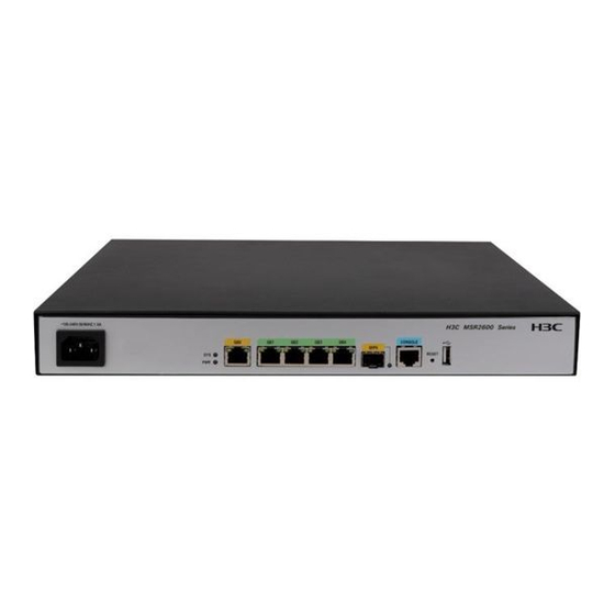
Page 31: Appendix A Chassis Views And Technical Specifications
(6) Reset button (RESET) (7) USB port Figure 20 Rear panel (1) SIC 2 (2) SIC 1 (3) Grounding terminal Technical specifications Table 7 Technical specifications Item MSR2600-6-X1-GL Console/AUX port Console port USB port GE copper port GE fiber port Reset button... - Page 32 Item MSR2600-6-X1-GL Memory 1GB DDR3 Flash 256 MB SIC slots Dimensions (H × W × D) (excluding rubber feet and 44.2 × 360 × 300 mm (1.74 × 14.17 × 11.81 in) mounting brackets) Rated AC voltage 100 to 240 VAC @ 50/60 Hz...
-
Page 33: Appendix B Leds
Appendix B LEDs Figure 21 LEDs (1) System status LED (SYS) (2) Power status LED (PWR) (3) LEDs for Gigabit Ethernet copper ports GE0 to GE4 (4) LED for Gigabit Ethernet fiber port SFP5 Table 8 LED description Status Description Comware has started with the configuration file and Slowly flashing green the router has booted up. -
Page 34: Appendix C Slot Arrangement
Appendix C Slot arrangement The router provides SIC slots. The fixed ports on the router panel are in slot 0. Table 9 Slot arrangement Router model Slot arrangement MSR2600-6-X1-GL : SIC slot... -
Page 35: Index
Index C E G I L M R S T V Rack requirements,4 Reset button usage guidelines,23 Cleanliness,2 Connecting interface cables,14 Connecting the AC power cord,16 Safety symbols,1 Connecting the console cable and setting terminal Scenario 1,22 parameters,15 Scenario 2,22 Cooling system,2 Scenario...
Need help?
Do you have a question about the MSR2600-6-X1-GL and is the answer not in the manual?
Questions and answers