Table of Contents
Advertisement
Quick Links
Download this manual
See also:
User Manual
Advertisement
Table of Contents
Troubleshooting

Related Manuals for H3C MSR 20


Summary of Contents for H3C MSR 20
-
Page 1: Installation Guide
H3C MSR 20 Routers Installation Guide Hangzhou H3C Technologies Co., Ltd. http://www.h3c.com Document version: T2-08047K-20101217-C-1.05... - Page 2 SecPro, SecPoint, SecEngine, SecPath, Comware, Secware, Storware, NQA, VVG, V G, V G, PSPT, XGbus, N-Bus, TiGem, InnoVision and HUASAN are trademarks of Hangzhou H3C Technologies Co., Ltd. All other trademarks that may be mentioned in this manual are the property of their respective owners Notice The information in this document is subject to change without notice.
- Page 3 Preface The H3C MSR 20 Routers Installation Guide describes how to install the H3C MSR 20 Routers, maintain software and hardware of the router, and solve problems you may encounter during the installation process. This preface includes: Audience • •...
-
Page 4: Obtaining Documentation
Obtaining documentation You can access the most up-to-date H3C product documentation on the World Wide Web at http://www.h3c.com. Click the links on the top navigation bar to obtain different categories of product documentation:... -
Page 5: Technical Support
– Provides information about products and technologies, as well as solutions. [Technical Support & Documents > Software Download] – Provides the documentation released with the software version. Technical support customer_service@h3c.com http://www.h3c.com Documentation feedback You can e-mail your comments about product documentation to info@h3c.com. We appreciate your comments. -
Page 6: Table Of Contents
Contents Overview ······································································································································································ 1 Introduction ········································································································································································1 Router Model and Structure ·············································································································································1 Hardware Specifications ·········································································································································1 MSR 20-20 Router····················································································································································2 MSR 20-21 Router····················································································································································4 MSR 20-40 Router····················································································································································6 Generic Modules·······························································································································································8 SIC and DSIC Interface Cards ································································································································8 ESM Module ·····························································································································································8 VPM and VCPM Module ·········································································································································9 Installation Preparations ············································································································································10 Requirements on Environment ······························································································································... - Page 7 Startup Process······················································································································································· 29 Configuration Fundamentals ········································································································································· 30 Basic Configuration Procedures··························································································································· 30 Command Line Interface······································································································································· 30 Arranging Slots and Numbering Interfaces········································································································ 31 Software Maintenance···············································································································································33 Introduction ····································································································································································· 33 Files ········································································································································································· 33 Software Maintenance Methods·························································································································· 34 Maintaining Application Program and Configuration Through Command Lines···················································· 35 Maintaining the Router Through TFTP Server ·····································································································...
-
Page 8: Overview
MSR 20 Routers were self-developed for use on enterprise-level networks. Depending on the network size, MSR 20 Routers can be either core routers on small and medium enterprise networks, or access routers for network branches on some large-sized enterprise networks. Therefore, MSR 20 Routers are suitable for the application on the carrier-level networks, such as telecom management networks and billing networks. -
Page 9: Msr 20-20 Router
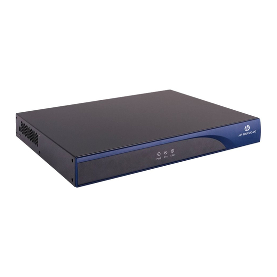
Do not unplug the USB device during USB data transmission; otherwise, data loss or even hardware • failures may occur. The USB interface does not support hot-swapping of USB modems from Sierra Wireless. • MSR 20-20 Router Appearance Front view... - Page 10 (8) Console port (CON) (9) Auxiliary port (AUX) (10) USB interface (11) CF card Panel LEDs The following table gives the features of MSR 20-20 router LEDs: Table 2 Front panel LEDs of an MSR 20-20 router Description Power LED: •...
-
Page 11: Msr 20-21 Router
Green means ESM card is operation normally. • Yellow means ESM card is malfunctioning. • Steady OFF means no ESM card is present. Table 3 Rear panel LEDs of an MSR 20-20 router Description • OFF means no link is present. LINK •... - Page 12 (10) USB interface (11) CF card (12) Fixed L2 switching port (LAN2 through LAN9) Panel LEDs The following table gives the features of MSR 20-21 router LEDs: Table 4 Front panel LEDs description of an MSR 20-21 router Description Power LED: •...
-
Page 13: Msr 20-40 Router
Steady OFF means no CF card is present or the present CF card cannot be identified by the system. MSR 20-40 Router Appearance Front view Figure 5 Front view of an MSR 20-40 (1) Power LED (POWER) (2) System LED (SYSTEM) (3) Console port (CONSOLE) (4) Auxiliary port (AUX) - Page 14 (5) SIC slot3 (6) SIC slot4 (7) Grounding terminal (8) LEDs Panel LEDs Description of LEDs on an MSR 20-40 router is as follows: Table 6 Front panel LEDs of an MSR 20-40 router Description Power LED: • ON means the circuit board supplies power normally.
-
Page 15: Generic Modules
MSR Series Routers Interface Module Manual. For the types of interface modules that each model of the MSR 20 routers can accommodate, refer to Appendix A Interface Card and Interface Module Purchase Guide in the MSR Series Routers Interface Module Manual. -
Page 16: Vpm And Vcpm Module
VCPM (Voice Co-Processing Module) processes the voice data in combination with VPM. Voice co-processing module (RT-VCPM) • 8-channel voice processing module (RT-VPM8) • 16-channel voice processing module (RT-VPM16) • 24-channel voice processing module (RT-VPM24) • 32-channel voice processing module (RT-VPM32) • NOTE: VPM/VCPM is only available on MSR 20-40. -
Page 17: Installation Preparations
Installation Preparations Requirements on Environment The MSR 20 routers are designed for indoor applications. To ensure the normal operation and prolong their service life, the following requirements for installation site must be met. Requirements on Temperature/Humidity To ensure the normal operation and prolong their service life, certain requirements on temperature and humidity in the equipment room shall be met. -
Page 18: Requirements On Electrostatic Discharge Prevention
0.01 Requirements on Electrostatic Discharge Prevention Although many antistatic considerations have been given to MSR 20, damage to the router’s circuit or even the whole equipment may still happen when the static electricity exceeds the tolerance threshold. In the communication network to which the routers are connected, static induction mainly comes from two aspects: external electric fields such as outdoor high voltage power line or thunder and internal environment like flooring materials or the whole equipment structure. -
Page 19: Checking The Rack
• As for the signal line outdoors to which the interface modules of MSR 20 routers are connected, such as ISDN line, telephone line, E1/T1 line, etc, a special lightning arrester should be installed at the input end of the signal line to enhance the lightning protection capability. - Page 20 Meters and equipment • Hub or LAN switch Console terminal (it could be a PC) • • Equipment related to the selected modules Multimeter • CAUTION: None of the above-mentioned installation tools, meters, and equipment are shipped with MSR 20 routers.
-
Page 21: Installation
For cabinet installation methods, refer to the part discussing cabinet installation. Skip this section if you want to mount your router on the tabletop or the rack of another vendor. Installing the Router Table 12 describes physical dimensions of three models of the MSR 20 routers. -
Page 22: Installing The Router On A Workbench
Installing the Router in a Cabinet You can install an MSR 20 router in a 19-inch standard cabinet, such as an H3C N68 rack. For the installation of an N68 rack, refer to N68 Cabinet Installation Guide. Mounting brackets... - Page 23 Step1 of the front panel or the rear panel of the router. Put the router in a rack tray. For MSR 20-40 routers, use dedicated ears mounted on the rear panel if no Step2 tray is available. Depending on the actual situation, slide the router along the chassis guides to an appropriate place.
-
Page 24: Installing Generic Modules
The power input end of MSR 20 router is connected to a noise filter. The neutral point of the noise filter is directly connected to the chassis and is called protection ground (PGND). The PGND wire must be well grounded, so as to safely conduct the faradism and leaky electricity to the earth ground, and thereby improve the capability of the whole device to guard against the electromagnetic interference. -
Page 25: Connecting The Power Cord
Connecting the Power Cord The MSR 20-20/20-21/20-40 router is available with AC-powered units. Power Input and PGND Table 13 Power input and PGND of the MSR 20-20/20-21/20-40 router Item Description Power input... -
Page 26: Connecting The Console Terminal
Step4 Connecting the Console Terminal Console port MSR 20 provides an RS232 asynchronous serial console (CON) port for router configuration, through which you can complete the configuration of the router. For its attributes, refer to Table Table 14 Attributes of the console port... -
Page 27: Fixed Interfaces
Fixed Interfaces Ethernet Interface Ethernet interface MSR 20 Routers are available with fixed 100Base-TX FE interface(s) and Ethernet modules/cards for expansion. For more information, refer to MSR Series Routers Interface Module Manual. The following table describes Ethernet interface attributes. Table 15 Attributes of the Ethernet interface... -
Page 28: Ethernet Switching Interface
View the LINK LED of the Ethernet interface: ON means a link is present. OFF means no link is present; Step2 check the line for the cause. Ethernet Switching Interface The MSR 20-21 Router is available with fixed 100Base-TX FE interface(s). The following table describes Ethernet switching interface attributes: Table 16 Attributes of the Ethernet switching interface Attribute... -
Page 29: Connecting Aux To A Modem
NOTE: MDI (media dependent interface is a typical type of Ethernet interface provided by network adapters. MDIX is crossover media-dependent interface, which is commonly found on a Hub or LAN switch. Ethernet cable Ethernet interfaces usually use category 5 twisted pair cables, as shown in the following figure: Figure 15 Ethernet cable Ethernet cables fit into the following two categories: •... -
Page 30: Interface Modules
PSTN and then to the remote device. For the configuration procedures, refer to MSR Series Routers Configuration Guide. Interface Modules The MSR 20 Routers are available with various types of interface modules. For detailed information refer to MSR Series Routers Interface Module Manual. Installing and Removing Interface Modules With support for removable slide rails, the MSR 20 routers deliver great flexibility and expandability by applying DSIC interface cards. -
Page 31: Slide Rail
Slide Rail SIC slide rail Figure 17 SIC slide rail Blank panel Figure 18 Blank panel Installing a DSIC Interface Card Follow these steps to install a DSIC interface card: Remove the blank panel covering the slot and keep it for future use. Step1 Determine the interface card type. -
Page 32: Removing A Dsic Interface Card
Figure 19 Remove the slide rail Figure 20 Install the DSIC card Removing a DSIC Interface Card After removing a DSIC card or when installing two SIC cards, you need to install a slide rail, which separates a DSIC slot into two SIC slots. Removal is in the reverse order of installation. Follow these steps to remove a DSIC card: Loosen the screws on the interface card and remove the card. -
Page 33: Startup And Configuration
Startup and Configuration Startup You can only configure the MSR 20 router through the console port if it is the first time you use it. Setting up Configuration Environment Connecting the router to a console terminal To set up the local configuration environment, RJ-45 connector of the console cable needs to be connected to the console port on the router, and DB-9 connector to the serial interface of a PC, as shown in the following figure. - Page 34 Figure 22 Setting the connection port in the local configuration Set terminal parameters. As shown in the following figure, in the properties dialog box of the serial Step2 interface, set the baud rate to 9600, data bit to 8, no parity check, stop bit to 1, and flow control to none. Then, click OK to return to the HyperTerminal window.
-
Page 35: Powering On The Router
Figure 24 Setting terminal type Powering on the Router Checking before power-on Check according to the following items before powering on the router. Whether the power cord and PGND wire are correctly connected. • • Whether the voltage of the power supply complies with the requirement of the router. Whether the console cable is correctly connected, whether the PC or terminal for configuration is •... -
Page 36: Startup Process
For local configuration, after you power on the router, you can see the startup banner. See section Startup Process. After completing the power-on self-test (POST), the system asks you to press <Enter>. When the prompt appears, you may proceed to configure the router. Startup Process After power-on or during the reboot process, the following information is displayed on the terminal: System application is starting... -
Page 37: Configuration Fundamentals
Command Line Interface Characteristics of the command line interface The command line interface of MSR 20 Routers provides a number of configuration commands, which can be used to configure and manage the router. The command line interface has the following... -
Page 38: Arranging Slots And Numbering Interfaces
Command line interface The command line interface of MSR 20 routers provides plenty of configuration commands. All the commands are grouped in system view. Each group corresponds to a view. The user can use these commands to switch between different configuration views. - Page 39 • from left to right. If you install an SIC- 1 FEA and an SIC-4FSW respectively in SLOT1 and SLOT2 on the AR MSR 20-20, the Ethernet interfaces are numbered as follows: Fixed Ethernet interfaces are Ethernet 0/0 and Ethernet 0/1;...
-
Page 40: Software Maintenance
Software Maintenance Introduction Files BootWare program file The file is used to boot an application. A complete BootWare file includes two segments: basic and extended. The basic section is used for the basic initialization of the system. • The extended section provides abundant human-computer interaction (HCI) functions and is used to •... -
Page 41: Software Maintenance Methods
NOTE: The application programs for system boot can be type M, B and S, but not type N. You can store them • in Flash memory, but only one for each. For example, if an M+B file exists, it is impossible to have another M or B file. -
Page 42: Maintaining Application Program And Configuration Through Command Lines
NOTE: The BootWare program is upgraded together with the Blinux application program. You do not need to • upgrade the BootWare separately. When upgrading the Blinux program, the system checks whether the running BootWare version is consistent with that in the updating host application program. If inconsistent, the system asks whether to upgrade the BootWare. -
Page 43: Maintaining The Router Through Tftp Server
Maintaining the Router Through TFTP Server In the TFTP service, the router is TFTP client and the file server is the TFTP server. You can enter commands on the terminal to upload or download configuration files or application programs to or from the file server. - Page 44 File uploaded successfully. Use the following command to download the startup.cfg file from the server to the router: <SYSTEM>tftp 192.168.1.1 get startup.cfg startup.cfg The file startup.cfg exists. Overwrite it?[Y/N]:y Verifying server file... Deleting the old file, please wait... File will be transferred in binary mode Downloading file from remote tftp server, please wait...\ TFTP: 1045 bytes received in 0 second(s)
-
Page 45: Maintaining The Router Through Ftp Server
Before using FTP, you need to install the FTP client. No FTP client is shipped with the H3C MSR 20 routers. In the following example, the FTP client application program is the built-in Windows XP FTP client. - Page 46 Figure 30 Maintain the router serving as the server Ethernet cable Router TFTP/FTP Server Console cable TFTP/FTP Client Configure the IP addresses of both sides on the same network. In this section, the IP address of the FTP client (PC) is set to 192.168.1.1, and that of the connected Ethernet interface on the router (Ethernet 0/0) is set to 192.168.1.2.
- Page 47 After you correctly enter the username and password, the system prompts login success. You can then maintain the router, for example, modify transmission mode and local path, and back up files. In this example, the main.bin file on the router is copied to the PC. ftp>...
-
Page 48: Bootware Menu
Configure the IP addresses of both sides on the same network. In this section, the IP address of the FTP server is set to 192.168.1.1, and that of the connected Ethernet interface on the router (Ethernet 0/0 in this example) is set to 192.168.1.2. Use the ping command to check the connectivity. Maintain the router through the terminal connected with the console interface of the router. - Page 49 MSR20-11 BootWare, Version 3.01 ************************************************************************** Compiled Date : Jul 7 2008 CPU Type : MPC8248 CPU L1 Cache : 16KB CPU Clock Speed : 400MHz Memory Type : SDRAM Memory Size : 384MB Memory Speed : 100MHz BootWare Size : 4096KB Flash Size : 4MB cfa0 Size...
-
Page 50: Bootware Submenus
Enter your choice(0-9): This menu is described as follows: Table 18 Main BootWare menu Item Description <1> Boot System Bootstrap. Enter the serial interface submenu. For details about <2> Enter Serial SubMenu the submenu, refer to “Serial interface submenu” on page 43. - Page 51 Enter your choice(0-5): The submenu is described as follows: Table 19 BootWare serial interface submenu Item Description <1> Download Application Program To SDRAM And Download an application program to SDRAM and run <2> Update Main Application File Upgrade the main application program. <3>...
- Page 52 |<1> Display All File(s) |<2> Set Application File type |<3> Set Configuration File type |<4> Delete File |<0> Exit To Main Menu ========================================================================== Enter your choice(0-4): The submenu is described as follows: Table 21 File control submenu Item Description <1> Display All File Display all files.
-
Page 53: Upgrading An Application Program Through An Ethernet Interface
Upgrading an Application Program Through an Ethernet Interface Enter 3 in the BootWare menu to enter the Ethernet interface submenu. For details about the submenu, refer to “BootWare Submenus” on page 43. Configuring Ethernet Interface Parameters Before upgrading an application program through an Ethernet interface, we need to configure the Ethernet interface on the router as follows: Enter 3 in the BootWare menu to enter the Ethernet interface submenu. -
Page 54: Upgrading Procedure
Parameter Description Configure the gateway IP address if the server and the client are not Gateway IP Address on the same network segment. FTP User Name This option is not available for TFTP. FTP User Password This option is not available for TFTP. NOTE: Upon upgrade failure, the system prompts “Loading failed”. - Page 55 CAUTION: No TFTP/FTP Server is shipped with the MSR 20 routers. Modify Ethernet interface parameters. For details, refer to “Configuring Ethernet Interface Parameters” Step2 on page 46. Enter 3 in the main BootWare menu to enter the Ethernet Interface submenu. For example, when...
-
Page 56: Upgrading Bootware Through Ethernet Interface
Enter 0 to return to the main BootWare menu. Enter 1 to boot the system. Step6 CAUTION: If the input file name is the same as the original one in the Flash memory, the system prompts that “The • file is exist, will you overwrite it? [Y/N]”. Enter Y to overwrite the original file. The new application program file will then overwrite the original file of this type, ensuring the uniqueness of the application program on the device. -
Page 57: Modifying Serial Interface Parameters
starts to transmit data packets. After a complete packet is received, the receiver checks the packet using the agreed method. • If the check is passed, the receiver sends an acknowledgement message to the sender. Upon receiving the message, the sender continues to send the next packet. If the check fails, the receiver sends a negative acknowledgement message to the sender. -
Page 58: Upgrading Bootware
Figure 34 Modify baud rate Select Call > Call to establish a new connection. Figure 35 Establish a new connection Press Enter to view the current baud rate and return to the previous menu. The system displays: The current baudrate is 115200 bps NOTE: Restore the baud rate in the HyperTerminal to 9600 bps after upgrading the BootWare. - Page 59 Enter 3 in the BootWare operation menu. The system displays: ===================<BOOTWARE OPERATION SERIAL SUB-MENU>=================== |<1> Update Full BootWare |<2> Update Extend BootWare |<3> Update Basic BootWare |<4> Modify Serial Interface Parameter |<0> Exit To Main Menu ========================================================================== Enter your choice(0-4): Enter 1, and the system displays: Please Start To Transfer File, Press <Ctrl+C>...
-
Page 60: Upgrading An Application Program Through A Serial Interface
NOTE: The file name, size and path vary in different situations. Before upgrading, check the current version of • BootWare and application program. Restore the baud rate in the HyperTerminal to 9600 bps after upgrading the BootWare. This ensures that •... - Page 61 Displaying all files Enter 1, and the system displays: Display all file(s) in cfa0 'M' = MAIN 'B' = BACKUP 'S' = SECURE 'N/A' = NOT ASSIGNED ========================================================================== |NO. Size(B) Time Type Name 640199 Dec/20/2007 09:53:16 N/A cfa0:/logfile/logfile.log 22165484 Dec/20/2007 09:18:10 B+S cfa0:/update.bin 1181 Dec/20/2007 09:42:54 N/A...
-
Page 62: Deleting Files
========================================================================== |<1> +Main |<2> -Main |<3> +Backup |<4> -Backup |<0> Exit ========================================================================== Enter your choice(0-4): You can set the file type to M (main) or B (backup) or cancel the setting by selecting digits 1 to 4. Refer to “Introduction” on page for details. -
Page 63: Bootware Password Loss
The system prompts the setting succeeds. When the main BootWare menu appears again, enter 0 to reboot the system. Step2 Set a new password in system view. Step3 [SYSTEM]user-interface console 0 [SYSTEM-ui-console0]authentication-mode password [SYSTEM-ui-console0]set authentication password simple 123456 The above information indicates that the password authentication is adopted on the console interface and the password is set to 123456 and stored in plain text. -
Page 64: Backing Up And Restoring Bootware
After you clear the super password, quit the menu and reboot the router, you can directly enter system view. The setting is valid for the first reboot of the router only. The super password will be restored after a second reboot. Backing Up and Restoring BootWare Enter 7 under the main BootWare menu to enter the BootWare operation submenu. -
Page 65: Hardware Maintenance
• Static shielding bag • NOTE: The tools are not available with the MSR 20. You must prepare one yourself. Opening/Closing Chassis Cover Power off the router and remove the power cord. Step1 Remove all cables of interface modules on the back panel (keep the ground cable connected). - Page 66 Figure 39 Turn the screwdriver in the hole on MSR 20-20/20-21 Figure 40 Remove/install captive screws of MSR 20-40 Figure 41 Turn the screwdriver on MSR 20-20/20-21...
-
Page 67: Internal Structure
• Use the memory bars provided by our company only. Otherwise, anomalies might occur to the device. • Internal Structure Figure 42 Internal structure of MSR 20-20/20-21 (1) Power module (2) Memory bar slot (3) ESM slot (4) Fan module... -
Page 68: Installing/Removing Cf Card
Figure 43 Internal structure of MSR 20-40 (1) Power module (2) CF card slot (3) SDRAM slot (4) ESM slot0 (5) ESM slot1 (6) SIC slot (7) Fan (8) VCPM slot (9) VPM slot Installing/Removing CF Card Structure Figure 44 Front view of CF card... -
Page 69: Removing Cf Card
Push the spring button into the slot completely, and make sure it only springs out with outside force. Step1 Press the CF card into the slot in correct orientation, and make sure it only springs out with outside force. Step2 Figure 45 Press the CF card into the slot NOTE: Make sure the CF card with correct application program is properly installed in the slot;... -
Page 70: Memory Bar Structure
Figure 47 Memory bar maintenance flow Start Start Prepare tools Prepare tools Turn off the power switch Turn off the power switch Locate the memory bar Locate the memory bar on the main board on the main board Remove the memory bar Remove the memory bar Install the memory bar Install the memory bar... -
Page 71: Memory Bar Slot
Memory Bar Slot Figure 49 Memory bar structure Installing/Removing Memory Bar Follow the steps below to install the memory bar: Make sure all power interfaces are shut down, and then proceed. Step1 Align the memory bar golden finger with the slot on the main board. Step2 Make the memory bar to form an angle of 45 degrees with the main board and insert it into the slot. -
Page 72: Installing/Removing Esm/Vcpm Card
Figure 51 Remove memory bar from the slot Installing/Removing ESM/VCPM Card Follow the steps below to install the ESM/VCPM card: Make sure all power interfaces are shut down, and then proceed. Step1 Open the chassis cover (refer to Opening/Closing Chassis Cover for details) to find the card. - Page 73 Figure 53 Fasten the card on the bracket with screws NOTE: Perform the steps inversely to remove the card.
-
Page 74: Troubleshooting
Troubleshooting Troubleshooting the Power System Symptom: The PWR LED on the PSU is OFF. Solution: Check that: The power switch on the router is turned on • The switch of the power source is turned on • The power cord is correctly connected •... -
Page 75: Troubleshooting Application Software Upgrade
Troubleshooting Application Software Upgrade Symptom 1: When upgrading the software using TFTP/FTP, the system displays: =========================<ETHERNET PARAMETER SET>========================= |Note: '.' = Clear field. '-' = Go to previous field. Ctrl+D = Quit. ========================================================================== Protocol (FTP or TFTP) :tftp ftp Load File Name :host Target File Name :target... - Page 76 Something wrong with the file. Solution: Fault occurs because an incorrect application file is downloaded. Download the correct application program file. NOTE: The bar code labels on the chassis and the FICs contain information about production and servicing. • Before you ask your agent for servicing, provide its bar code. •...
-
Page 77: Index
Index Replacing Memory Bar Router Model and Structure Backing Up and Restoring BootWare BootWare Menu Startup Configuration Fundamentals Connecting the Console Terminal Troubleshooting Application Software Upgrade Connecting the PGND Cable Troubleshooting the Configuration System Connecting the Power Cord Troubleshooting the Power System Dealing with Password Loss Upgrading an Application Program through a Serial Interface...
Need help?
Do you have a question about the MSR 20 and is the answer not in the manual?
Questions and answers