Table of Contents
Advertisement
VD2121CAGL
Posto esterno
External door station
AGL100VD
Posto esterno videocitofonico
External door station
Plaque de rue vidéophonique
Placa de calle de videoportero
Posto externo de vídeo-porteiro
Videotürstation
Posto interno
Internal station
Poste intérieur
Unidad interna
Aparelho interno
Videohaustelefon
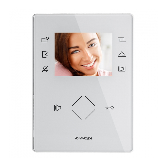
ZH1262B - ZH1262W
Videocitofono con OSD
Videointercom with OSD
Moniteur avec OSD
Videoportero con OSD
Vídeo-porteiro com OSD
Videohaustelefon mit OSD
Plaque de rue
AG42CDUO
Modulo telecamera a colori con gruppo fonico incor-
porato
Colour camera module with integrated door speaker
Caméra en couleurs avec module phonique intégré
Cámara en colores con grupo fónico integrado
Telecâmara em cores com porteiro integrado
Farbe Videokamera mit
integrierter Türfreisprecheinrichtung
Alimentatori e distributore di linea
Power supplies and line distributor
Alimentations et distributeur de ligne
Alimentadores y distribuidor de línea
Alimentadores e distribuidor de linha
Netzgeräte und Leitungsentkoppler
DV2420
Distributore di linea
Line distributor
Distributeur de ligne
Distribuidor del línea
Distribuidor de linha
Leitungsentkoppler
Mi 2478
ZH1262AGLB
ZH1262AGLW
Placa de calle
AGL21S
Gruppi pulsante singolo
Single button units
Blocs à un bouton-poussoir
Grupos pulsador individual
Grupos botão individual
Zusatztastenmodule
2221ML
Alimentatore di linea
Line power supply
Alimentation de ligne
Alimentador de línea
Alimentador de linha
Bustreiber
- 1 -
Italiano
English
Français
Español
Português
Deutsch
Posto externo
Türstation
AGL20
Modulo neutro
Blank module
Module neutre
Módulo neutro
Módulo neutro
Leermodul
2220S
Trasformatore
Transformer
Alimentation
Alimentador
Alimentador
Netzgerät
Mi 2478
Advertisement
Table of Contents

Subscribe to Our Youtube Channel
Related Manuals for FARFISA INTERCOMS ZHERO ZH1262AGLB


Summary of Contents for FARFISA INTERCOMS ZHERO ZH1262AGLB
- Page 1 Mi 2478 Italiano English Français Español Português ZH1262AGLB Deutsch ZH1262AGLW VD2121CAGL Posto esterno External door station Plaque de rue Placa de calle Posto externo Türstation AGL20 AGL100VD AG42CDUO AGL21S Modulo telecamera a colori con gruppo fonico incor- Gruppi pulsante singolo Modulo neutro Posto esterno videocitofonico Single button units...
-
Page 2: Safety Notices
AVVERTENZE DI SICUREZZA SAFETY NOTICES NOTICE DE SECURITÉ Read the instructions contained in this Leggere attentamente le avvertenze conte- Lire attentivement les instructions contenues manual carefully because they provide nute nel presente manuale perché fornisco- dans le présent manuel parce qu'ils fournis- important information about safe instal- sent d'importants renseignements concer- no importanti informazioni riguardanti la... - Page 3 POSTO INTERNO INTERNAL STATION POSTE INTÉRIEUR UNIDAD INTERNA ZH1262 APARELHO INTERNO VIDEOHAUSTELEFON Installazione 3 - Togliere la morsettiera dal videocitofono. Installation - Unplug the terminal block from the videointercom. Installation - Enlever le bornier du vidéophone. - Extraer la caja de bornes del videoportero. Instalación - Retirar a caixa de terminais do vídeo-porteiro.
- Page 4 - Fissare il videocitofono alla staffa. - Smontaggio del videocitofono. - Fix the video intercom to the wall bracket. - Dismounting the video intercom. - Fixer le vidéophone sur le support de fixation. - Démontage du vidéophone. - Asegurar el videoportero al soporte de fijación. - Desmontaje del videoportero.
- Page 5 Audio adjustments Regolazioni audio Réglages audio In conversazione o durante la chiamata è Audio level and ringtone volume can be Durant la conversation ou l’appel, il est possi- possibile variare il volume dell'audio o della adjusted during conversation by means of ble de varier le volume du son ou de la sonnerie suoneria agendo sugli appositi comandi (ve- special controls (see chapter 4 "Operation"...
- Page 6 Dati tecnici Données techniques Technical characteristics Alimentazione direttamente dalla linea Power supply directly from the line Alimentation directe depuis la ligne Assorbimento - a riposo: Stand-by current: Absorption - à repos: - in funzionamento: 280mA Operating current: - pendant le fonctionnement: 280mA 280mA Schermo:...
- Page 7 POSTO ESTERNO EXTERNAL DOOR STATION PLAQUE DE RUE PLACA DE CALLE POSTO EXTERNO VD2121CAG - VD2121CAGL TÜRSTATION Installazione Installation Installation Instalación Instalação Installation Applicazione dei pulsanti (o modulo neutro) sulla placca esterna Application of buttons (or blank module) on external plate Application des boutons-poussoirs (ou module neutre) sur la plaque de rue Aplicación de los pulsadores (o módulo neutro) en la placa...
- Page 8 Technical data Dati tecnici Données techniques Power supply: 13Vac±1V Alimentazione: 13Vca±1V Alimentation: 13Vca±1 Assorbimento: 0,8A Absorption: 0.8A Absorption: 0,8A Video signal standard: Standard segnale video: Standard signal vidéo: Illuminazione minima: 2,5 Lux Minimum lighting: 2.5 Lux Eclairage minimum: 2,5 Lux Led: 4 (bianchi) + 2 (rossi) LED's:...
- Page 9 Regolazioni - Adjustments - Réglages - Ajustes - Regulações - Einstellungen Volume adjustment Regolazione volumi Per regolare i volumi del microfono e dell'altoparlante, agire sui trimmer Use trimmers to adjust the volume of microphone and speaker. Anti-feedback adjustment Regolazione dell’antilocale In case of "feedback"...
- Page 10 ALIMENTATORI - POWER SUPPLIES - ALIMENTATIONS - ALIMENTADORES - NETZGERÄTE Art. 2220S " " " TRANSFORMATEUR TRASFORMATORE TRANSFORMER Technical data Données techniques Dati tecnici Tension de secteur: 127V ou 220-230Vca Tensione di rete: 127V o 220-230Vca Mains voltage: 127V or 220-230VAC Fréquence: 50 ÷...
-
Page 11: Line Power Supply
" Art. 2221ML " " ALIMENTATION DE LIGNE ALIMENTATORE DI LINEA LINE POWER SUPPLY Dati tecnici Données techniques Technical data Alimentazione di rete: (0 / 127) 127Vca; Tension de secteur: (0 / 127) 127Vca Mains voltage: (0 / 127) 127VAC; (0 / 230) 220-230Vca (0 / 230) 220-230Vca (0 / 230) 220-230VAC... - Page 12 Art.2302 Farfisa cable Tabella delle distanze massime garantite Cavo Farfisa art.2302 Cavo a 2 conduttori twistato con- Twisted pair cable specified for Table of the maximum permitted distances sigliato per la realizzazione di im- the digital installation with DUO Tableau des distances maximales garanties pianti digitali DUO System.
- Page 13 Electrical door lock Serratura elettrica Gâche électrique Il segnale video può essere disturbato durante The video signal may be disturbed during the Le signal vidéo peut être perturbé pendant l'azionamento della serratura elettrica. Per evi- operation of the electrical lock. To avoid this l’actionnement de la gâche électrique.
- Page 14 ESQUEMAS DE INSTALACIÓN SCHEMI INSTALLATIVI INSTALLATION DIAGRAMS ESQUEMAS DE INSTALAÇÃO SCHALTPLÄNEN SCHÉMAS D'INSTALLATION SISTEMA DE VIDEOPORTERO MONOFAMILIAR IMPIANTO VIDEOCITOFONICO MONOFAMILIARE ONE-WAY VIDEOINTERCOM SYSTEM INSTALAÇÃO DE VÍDEOPORTEIRO MONOFAMILIAR INSTALLATION VIDEOPHONIQUE A UNE DIRECTION EINFAMILIEN-VIDEOSPRECHANLAGE VD2121CAGL AGL21 art.DV2420 1 2 3 4 5 LM LM ZH1262B art.2220S...
- Page 15 IMPIANTO VIDEOCITOFONICO MULTIFAMILIARE SISTEMA DE VIDEOPORTERO MULTIFAMILIAR MULTI-FAMILY VIDEOINTERCOM SYSTEM INSTALAÇÃO DE VÍDEO-PORTEIRO MULTIFAMILIAR INSTALLATION VIDEOPHONIQUE A PLUSIEURS DIRECTIONS MEHRFAMILIEN-VIDEOSPRECHANLAGE 1 2 3 4 5 1 2 3 4 5 1 2 3 4 5 ZH1262 DV2421Q 1 2 3 4 5 DV2422A 1 2 3 4 5 ZH1262...
- Page 16 Entering codes or addresses Dial the code number you have chosen for the - Codes and/or addresses must have three digits external door station and press Pn to confirm; you hear the confirmation tone and the red (hundreds, tens, units); codes and/or addresses The push-button of VD2121CAGL external door LEDs go back ON without flashing.
- Page 17 dial the number of seconds you want the door on without flashing. a - dial the address of the extension (codes lock to stay ON (3 digits from 000 to 120); Note . The programming is not saved until all from 001 to 200) or the address actuator (codes from 211 to 220) following the instructions press Pn;...
-
Page 18: Main Functions Of The Keys
2 MAIN FUNCTIONS OF THE KEYS The 6 keys on screen side and the wheel sensor allow the user to access the operating modes, setup and programming pages of the videointercom; these keys modify their function according to the indications shown on the screen. The “... - Page 19 PROGRAMMING Access the main menu With the monitor in stand-by and no other videointercom To ensure correct operation of the videointercom, the latter must turned ON in the system, access the menu by touching be programmed by the installer; incorrect programming may any active point of the wheel sensor.
-
Page 20: Installation Wizard
3.1 Installation wizard To enable easy device programming, at first power-ON (or subsequently if selected in “Set-up” menu) will start an installation wizard. This procedure enables fast and easy setup of essential parameters for videointercom operation such as device address and room number, the latter required only if there are several devices installed in the same apartment. For further details refer to the following pictures. - Page 21 3.2 Programming Installation wizard enables setting user addresses only; all the other parameters can be set proceeding as follows: - operate the wheel to access the main menu; - select “Settings” (run the unlock procedure) access sub-menus to set the required parameters following the indications below.
-
Page 22: System Menu
System Menu System settings. This menu allows the user to set user addresses, room addresses, additional parameters and Forwarding A1 (see “System menu” section) . Address Forwarding Forwarding Default settings. It enables resetting the factory settings of the device; if there are any intercommunicating devices, Room entrances and actuations programmed, such entries will not be deleted. - Page 23 3.3 MAIN MENU DIAGRAM Intercommunicatings List of intercommunication devices stored in the videointercom Entrances List of entrances present in the system. Actuators List of actuator s present in the system Ringtones - Pre-listening and assignment of ringing melodies to individual intercommunicatin calls, calls from door stations...
-
Page 24: Set-Up Menu Diagram
3.4 SET-UP MENU DIAGRAM Settings - This menu is reserved exclusively to qualified staff; therefore, it is protected by password; to access the menu follow the indications given in the main menu at page 33. Intercommunicating - Here the user can enter the names and addresses of intercommunication devices or to modify the data stored previously;... -
Page 25: Operation
4 OPERATION Videointercom Access the main menu Following an incoming call from the outside or by touching the With the monitor in stand-by and no other videointercom key “ ”, on the screen is displayed an image for about 30 turned ON within the installation, access the menu by touching any active point of the sensor wheel. - Page 26 Saisir des codes ou des adresses Entrer en mode de programmation en sui- vant les indications détaillées dans le chapitre - Les codes et/ou les adresses à mémoriser “ Entrer en mode de programmation ”. doivent toujours être composés de trois chiffres Le bouton-poussoir d'appel de la plaque de rue Saisir le code 111 et appuyer sur Pn;...
- Page 27 manière continue; désactivation, tandis qu’une tonalité aiguë est tion d’activation de la caméra; on entend une continuer en saisissant le code d’une nouvelle générée pour en indiquer l’activation; tonalité de confirmation; programmation ou quitter en déplaçant le pon- b - appuyer sur “Pn” pou confirmer et passer à quitter la programmation en déplaçant le pon- la programmation du mode successif;...
- Page 28 2 PRINCIPALES FONCTIONS DES TOUCHES Les 6 touches à côté de l’écran et le rotor central (wheel) permettent d’accéder aux modes de fonctionnement, de configuration et de programmation du vidéophonie et varient leur fonction en fonction des indications reportées sur l’écran. Les touches “...
- Page 29 PROGRAMMATION Accéder au menu principal Quand l’écran est éteint et qu’aucun autre vidéophone Pour pouvoir fonctionner correctement, le vidéophone doit être de l’installation n’est allumé, il est possible d’accéder au programmé par l’installateur; une programmation erronée peut menu en touchant n’importe quel point actif du rotor. Sur compromettre le bon fonctionnement du vidéophone.
- Page 30 3.1 Procédure guidée pour le premier allumage Pour faciliter la programmation du dispositif, au premier démarrage (ou par la suite si sélectionnée dans le menu “Réglages”), une procédure automatique de programmation facilitée démarre. Cette procédure permet la saisie rapide et simple des paramètres essentiels pour le fonctionnement du vidéophone qui sont l’adresse du dispositif et l’éventuel numéro de pièce nécessaire seulement si sont présents plusieurs appareils dans le même appartement.
- Page 31 3.2 Programmation La programmation simplifiée permet d’afficher juste l’adresse utilisateur, pour toutes les autres programmations, il faut procéder de la manière suivante: - à l’aide du rotor, accéder au menu principal; - sélectionner "Réglages" (effectuer la procédure de déblocage) accéder aux différents sous-menus pour effectuer les programmations nécessaires en suivant les indications reportées ci-dessous.
-
Page 32: Menu Du Système
Système. À l’intérieur de ce menu, il est possible de Menu du système programmer les adresses utilisateur, de pièce, supplémentaires et de relance A1 (voir paragraphe “menu du système”) . Adresse Relance A1 Par défaut. Il permet de restaurer le dispositif avec les valeurs d’usine;... - Page 33 3.3 SCHÉMA DU MENU PRINCIPAL Intercommunicants - Liste des appareils intercommuni ants mémorisés dans le dispositif. Entrées - Liste des entrées présentes dans le système. Actionneurs - Liste des actionneurs présentes dans le système. Sonneries - Écoute et attribution des sonneries en les combinant aux appels intercommunicants, venant de l extérieur et de l étage (sonnette).
- Page 34 3.4 SCHÉMA DU MENU RÈGLAGES Réglages - Ce menu est réservé seulement à un personnel expert ce qui explique pourquoi son accès est protégé; pour y arriver, suivre les indications du menu principal page 43. Intercommunicants - à l intérieur, il est possible de saisir les noms et les adresses des appareils intercommunicants ou de modifier celles précédemment mémorisées;...
-
Page 35: Accéder Au Menu Principal
4 FONCTIONNEMENT Vidéophonie Accéder au menu principal Suite à un appel de l’extérieur ou en touchant la touche “ ”, Quand l’écran est éteint et qu’aucun autre vidéophone de sur l’écran apparaît l’image pendant environ 30 secondes. l’installation n’est allumé, il est possible d’accéder au menu en touchant n’importe quel point actif du rotor. - Page 36 Mi 2478 - 76 -...
Need help?
Do you have a question about the ZHERO ZH1262AGLB and is the answer not in the manual?
Questions and answers