
Related Manuals for BK Precision 1696B


Summary of Contents for BK Precision 1696B
- Page 1 GlobalTestSupply www. .com Find Quality Products Online at: sales@GlobalTestSupply.com...
-
Page 2: Safety Summary
Safety Summary The following safety precautions apply to both operating and maintenance personnel and must be followed during all phases of operation, service, and repair of this instrument. Before applying power to this instrument: • Read and understand the safety and operational information in this manual. •... - Page 3 Electrical Power This instrument is intended to be powered from a CATEGORY II mains power environment. The mains power should be 115 V RMS or 230 V RMS. Use only the power cord supplied with the instrument and ensure it is appropriate for your country of use.
- Page 4 Do not operate instrument if damaged If the instrument is damaged, appears to be damaged, or if any liquid, chemical, or other material gets on or inside the instrument, remove the instrument’s power cord, remove the instrument from service, label it as not to be operated, and return the instrument to B&K Precision for repair.
- Page 5 Do not substitute parts that are not approved by B&K Precision or modify this instrument. Return the instrument to B&K Precision for service and repair to ensure that safety and performance features are maintained. For continued safe use of the instrument •...
-
Page 6: Table Of Contents
Contents IMPORTANT SAFETY INSTRUCTIONS Precautions Product Overview Package Contents Power Requirements Interface and Controls Basic Operation Setting Voltage and Current by Rotary Knob and Up/Down Keys Setting Voltage and Current Using Keypad Operating Instructions Output Enable Output Disable Locking the Keypad and Rotary Knob Unlocking the Keypad and Rotary Knob Setting the RS-485 Address Setting the Upper Voltage Limit... -
Page 7: Important Safety Instructions
IMPORTANT SAFETY INSTRUCTIONS 1. Do not use this apparatus near water. 2. Clean only with dry cloth. 3. Do not block any ventilation openings. 4. Do not install unit near any heat source or heating emitting devices. 5. Prevent the power cord from being walked on or pinched. 6. -
Page 8: Product Overview
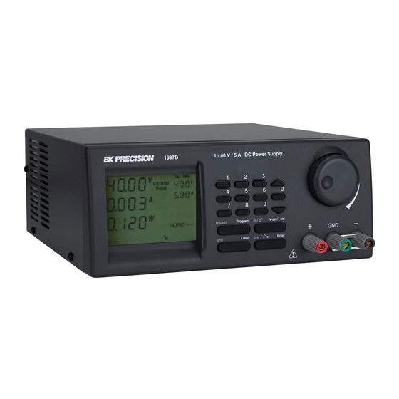
Product Overview 2.1 Package Contents • Power Supply (1696B, 1697B or 1698B) • Power cord • USB cable 2.2 Power Requirements Parameter Value Voltage 100 - 240 VAC Frequency 50/60 Hz Fuse 4A Slow Blow 250V 2.3 Interface and Controls... -
Page 9: Basic Operation
Basic Operation 3.1 Setting Voltage and Current by Rotary Knob and Up/Down Keys 1. Press to switch between setting voltage and current. 2. Rotate control knob or press to set voltage/current level. Press the control knob to toggle the cursor position. 3.2 Setting Voltage and Current Using Keypad 1. -
Page 10: Operating Instructions
Operating Instructions 4.1 Output Enable 1. Press 2. Press within 3 seconds to ENABLE output 4.2 Output Disable 1. Press 2. Press within 3 seconds to DISABLE output 4.3 Locking the Keypad and Rotary Knob 1. Press 2. Press within 3 seconds to lock keypad and rotary knob 4.4 Unlocking the Keypad and Rotary Knob 1. -
Page 11: Enable Output At Power Up
1. Press 2. Press on the numeric keypad within 3 seconds to enter upper voltage limit adjustment menu. The first line says “Over” and the second if the voltage limit setting. 3. Use the numeric keypad to input upper voltage limit. 4. - Page 12 1. Press 2. Press on numeric keypad within 3 seconds to enter into SCPI enable/disable menu. 3. Use the rotary knob to toggle between ‘Y’ to enable SCPI and ‘N’ to disable SCPI command protocol and use the extended protocol command set instead. 4.
-
Page 13: Using Programming Features
Using Programming Features 5.1 Preset Program 1. Press Program 2. Use the numeric keypad thru to select a preset voltage and current value. 3. Use to adjust preset voltage and current values. 4. Press within 3 seconds to confirm or press to exit program setting. -
Page 14: Maintenance
Maintenance 6.1 Recalibration The purpose of recalibration is to reduce the difference between the set values and the displayed values on the LCD display. Recalibration is only required when this difference is greater than 0.1 V for voltage or -0.01 A / +0.02 A for current. -
Page 15: Pc Software Control And Installation
PC Software Control and Installation The PC software provides remote communication, data logging, front panel emulation, and timed programming capabilities using the USB or RS-485 interfaces. The software supports Windows 7, 8, 8.1, 10. Note: Do not connect both USB and RS-485 simultaneously. 7.1 USB Driver Installation Figure 7.1 Download Link 1. -
Page 16: Multi-Unit Control
Figure 7.3 Figure 7.4 4. Click “Next” to continue. Figure 7.4 5. Select a destination location for the software. Figure 7.5 6. Select a location for the software shortcut.Figure 7.6 7. Check the box if you would like to create a desktop shortcut and click “Next” to continue. Figure 7.7 8. -
Page 17: Setup A New Instrument
Figure 7.5 Figure 7.6 Also, the software uses the “SCPI” protocol, this must be enabled, see Section 7.4.2. With the instrument connected, open the PC software. Figure 7.11 shows the screen to expect when the software starts. If there is already a saved connection the software will automatically connect to the instrument. - Page 18 Figure 7.7 Figure 7.8 • Select the “Setting” tab. See Figure 7.12 • Click on “Edit” to access the connection settings. See Figure 7.13 Note: When using USB: Only connection name, connection type, and COMM port are required. See Figure 7.14 GlobalTestSupply www.
-
Page 19: Enable Scpi Protocol
Figure 7.9 Connection diagram for multiple power supply control Figure 7.10 Connection diagram between USB adapter and RS-485 connectors • Type in a connection name, select USB from the drop down, and select the correct COMM port assigned by your PC. Check the windows the device manager to determine the correct COMM port. -
Page 20: External Timed Program
Figure 7.11 Figure 7.12 7.4.4 External Timed Program External Timed Program is completely controlled by the PC. The PC counts the step time and changes the specific voltage and current levels of the power supply. Configure up to 20 user defined voltage, current, and duration steps. 1. -
Page 21: Data Logging
Figure 7.13 Figure 7.14 7.4.6 Data Logging Data Log allows can be used to view present or stored output data, see 7.24. Data can be saved and exported Figure as .CSV spreadsheet file or sent to a printer. 7.4.7 Data Log Sampling Time and Voltage Upper Limit (UVL) Setting Under the “Setting”... - Page 22 Figure 7.16 Figure 7.18 GlobalTestSupply www. .com Find Quality Products Online at: sales@GlobalTestSupply.com...
- Page 23 Figure 7.19 Figure 7.20 Figure 7.21 GlobalTestSupply www. .com Find Quality Products Online at: sales@GlobalTestSupply.com...
- Page 24 Figure 7.22 Figure 7.23 Figure 7.24 Figure 7.25 GlobalTestSupply www. .com Find Quality Products Online at: sales@GlobalTestSupply.com...
-
Page 25: Specifications
Specifications Note: All specifications apply to the unit after: 1. A temperature stabilization time of 15 minutes over an ambient temperature range of 23 C ± 5 ∘ ∘ 2. Short correction operation performed before making measurement. Specifications are subject to change without notice. GlobalTestSupply www. -
Page 26: Service Information
Programmable DC Power Supplies Models 1696B, 1697B & 1698B Specifications Note: All specifications apply to the unit after a temperature stabilization time of 30 minutes over an ambient temperature range of 23 °C ± 5 °C. Model 1696B 1697B 1698B...
Need help?
Do you have a question about the 1696B and is the answer not in the manual?
Questions and answers