
Related Manuals for BK Precision 1653A


Summary of Contents for BK Precision 1653A
- Page 1 INSTRUCTION MANUAL MODELS 1653A & 1655A MODELOS 1653A & 1655A MANUAL DE INSTRUCCIÓN Isolated-Variable AC POWER SUPPLY Aislada, variable FUENTE DE PODER DE AC...
-
Page 2: Test Instrument Safety
The B+K Precision Models 1655A and 1653A AC Power Supplies are sources of high voltage ac. The person using the instrument should be a qualified electronics technician or otherwise trained and qualified to work with high voltage. -
Page 3: Ac Power Supply
Instruction Manual MODELS 1653A & 1655A Isolated, Variable AC POWER SUPPLY 22820 Savi Ranch Parkway Yorba Linda, CA 92887 www.bkprecision.com... -
Page 4: Table Of Contents
TABLE OF CONTENTS page TEST INSTRUMENT SAFETY ..... inside front cover page CIRCUIT DESCRIPTION............29 FEATURES................3 MAINTENANCE AND CALIBRATION........30 SPECIFICATIONS ..............4 Preventive Maintenance...............30 CONTROLS AND INDICATORS ..........6 Returning for Service..............30 OPERATING INSTRUCTIONS..........12 Fuse Replacement................30 Precautions ................13 Auto-Transformer Brush Replacement........31 Troubleshooting: Using the AC Power Supply as an Calibration Adjustments..............31... -
Page 5: Features
FEATURES Unless otherwise stated, all information in this section applies equally to Model 1653A and 4655A WIDE VOLTAGE RANGE BUILT-IN METER Output voltage continuously variable from 0 to 150VAC. Model 1655A WIDE CURRENT RANGE 3-1/4 inch meter. Multi-color scales. Overrange Model 1655A Heavy duty unit handles virtually all servicing needs. -
Page 6: Specifications
SPECIFICATIONS MODEL 1655A MODEL 1653A OUTPUT ISOLATION OUTPUT ISOLATION Leakage less than 0.1mA (25ºC, 50% relative humidity.) Leakage less than 0.1mA (25ºC, 50% relative humidity) VOLTAGE ADJUSTMENT RANGE 0-150VAC, with input at 120VAC VOLTAGE ADJUSTMENT RANGE VOLTAGE/CURRENT SENSING 0-150VAC, with input at 120VAC... - Page 7 SPECIFICATIONS MODEL 1655A MODEL 1653A INPUT POWER INPUT POWER 120 VAC 10%, 60Hz, 600VA. 120 VAC ±10%, 60Hz, 300 VA. OPERATING TEMPERATURE RANGE OPERATING TEMPERATURE RANGE 0° C to +40°C. 0°C to +40°C. STORAGE TEMPERATURE -30° C to +60°C. STORAGE TEMPERATURE -30°C TO +60°C.
-
Page 8: Controls And Indicators
Voltage must be preset to 120VAC for accurate the previous selection. The following selections are leakage measurements. available: Model 1653A VOLTS. Connects meter to measure voltage at Alternate action pushbutton switch selects function of meter. ISOLATED OUTPUT. Use 0-150 VOLTS Push once to latch button in AMPS (in) position. - Page 9 CONTROLS AND INDICATORS ISOLATED OUTPUT Receptacle(s). Isolated, 11. Fuse. variable ac voltage outlet(s). The equipment under test plugs in here. Single outlet on Model 1653A. Dual Model 1655A outlets on Model 1655A. 4A fuse protects auto-transformer against excessive output current at low voltages which may not trip the input *Leakage Probe.
- Page 10 CONTROLS AND INDICATORS Figure 1. Front Panel Controls and Indicators, Model 1655A...
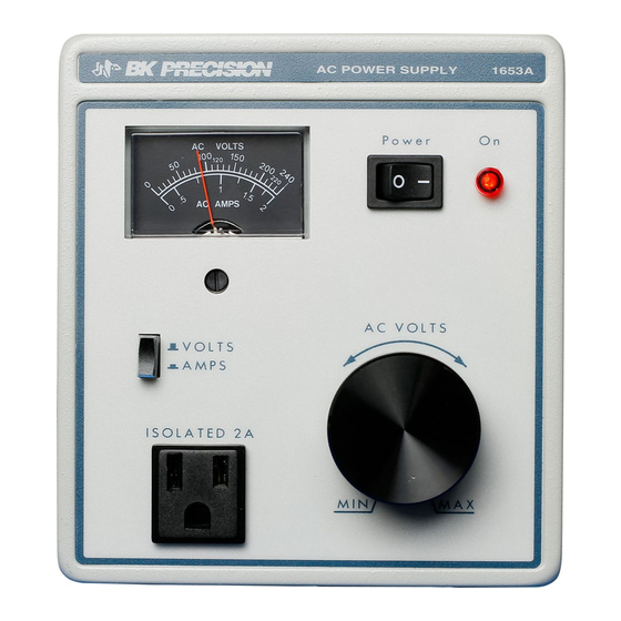
- Page 11 CONTROLS AND INDICATORS Figure 2. Front Panel Controls and Indicators, Model 1653A...
- Page 12 CONTROLS AND INDICATORS Figure 3. Rear Panel Controls and Indicators, Model 1655A...
- Page 13 CONTROLS AND INDICATORS Figure 4. Rear Panel Controls and Indicators, Model 1653A...
-
Page 14: Operating Instructions
PRECAUTIONS become excessive and cause failure of the unit. Similarly, avoid SAFETY The Model 1655A and 1653A AC Power Supplies are sources operating locations near sources of heat. of high voltage ac. Improper or careless use could result in fatal electrical shock. - Page 15 OPERATING INSTRUCTIONS PRECAUTIONS Figure 5. Observe Caution Above 130V.
-
Page 16: Precautions
Model 1655A, while a 3A fuse is used for Model 1653A. Additionally, output fuses limit the output of the 1655A to 4 amps and the 1653A to 3 amps at low voltages that would not open the input protective device. - Page 17 OPERATING INSTRUCTIONS PRECAUTIONS Figure 6. Maximum Current Considerations.
-
Page 18: Troubleshooting: Using The Ac Power Supply As An Isolation Transformer
Troubleshooting: Use As Isolation Transformer OPERATING INSTRUCTIONS TROUBLESHOOTING: USING THE AC POWER SUPPLY AS ISOLATION TRANSFORMER Transformerless Half-Wave Rectifier Equipment Another commonly used transformerless power supply circuit THE HAZARD is a half-wave rectifier where one side of the ac power line connects directly to the chassis (also shown in Fig. - Page 19 OPERATING INSTRUCTIONS Troubleshooting: Use As Isolation Transformer Figure 7. Servicing “Hot Chassis” Equipment Can Pose a Serious Shock Hazard.
- Page 20 OPERATING INSTRUCTIONS wire power cord as “hot chassis” and use the ISOLATED THE SOLUTION OUTPUT of the 1655A or 1653A AC Power Supply for servicing Don’t Ground the Chassis Simply connecting a test lead from the chassis to a good earth such equipment.
- Page 21 OPERATING INSTRUCTIONS Troubleshooting: Use As Isolation Transformer Figure 8. Eliminating the Hazard of Servicing Transformerless Equipment...
- Page 22 Troubleshooting: Use As Isolation Transformer OPERATING INSTRUCTIONS Figure 9. Using the AC Power Supply as an Isolation Transformer...
-
Page 23: Troubleshooting: Using The Ac Power Supply As A Variable Ac Voltage Source
Troubleshooting: Use As Variable Voltage Source TROUBLESHOOTING: USING THE AC POWER SUPPLY AS A VARIABLE AC VOLTAGE SOURCE Using the Model 1655A or 1653A AC Power Supply as shown VARIABLE VOLTAGE SOURCE in Fig. 10, voltage can be set to 0 volt and slowly increased while Both the Model 1655A and 1653A AC Power Supplies offer monitoring the current. - Page 24 Troubleshooting: Use As Variable Voltage Source OPERATING INSTRUCTIONS Figure 10. Using the Variable Voltage Feature to Troubleshoot Equipment with Short Circuit...
-
Page 25: Troubleshooting: Using The Ac Power Supply To Measure Electrical Loads
Measurement of electrical load is extremely simple when using information is not available, the normal current drain is typically the Model 1655A or 1653A AC Power Supply as the power 60% to 80% of the rated current of the circuit breaker or line fuse. - Page 26 Troubleshooting: Load Measurement OPERATING INSTRUCTIONS Figure 11. Measuring Electrical Load...
-
Page 27: Using The Model 1655A As A Leakage Tester
OPERATING INSTRUCTIONS Leakage Tester USING THE MODEL 1655A AS A LEAKAGE TESTER The equipment under test remains connected to the STANDARD LEAKAGE TEST ISOLATED OUTPUT, just as if it was for servicing. The voltage As previously mentioned, most equipment with a 2-wire ac was probably already preset to 120 volts at the conclusion of power plug is the “hot chassis”... - Page 28 Leakage Tester OPERATING INSTRUCTIONS Figure 12. Power Line Leakage Testing.
-
Page 29: Soldering Iron Temperature Control
OPERATING INSTRUCTIONS Soldering Iron Temperature Control SOLDERING IRON TEMPERATURE CONTROL (MODE 1655A ONLY) oxidation of the tip. This setting keeps the iron warm enough that THE NEED FOR TEMPERATURE CONTROL Most servicing work requires the use of a soldering iron. If the it can be quickly brought to operating temperature when needed. - Page 30 Soldering Iron Temperature Control OPERATING INSTRUCTIONS Figure 13. Using the Variable Soldering Iron Temperature Feature.
-
Page 31: Circuit Description
ISOLATED OUTPUT receptacle(s). of the 0.5-ohm resistors. Model 1653A is protected by input fuse F1, while Model When the LEAKAGE function is selected (Model 1655A only) 1655A uses circuit breaker CB1. This limits the maximum input the current from the leakage probe is applied to the meter circuit. -
Page 32: Maintenance And Calibration
(Table 1) above 130 volts, and to allow sufficient cooling time when operating Model 1655A at Model 1653A greater than 3 amps outlet. If the instrument is severely overloaded at higher output voltages, fuse F1 on the rear panel will blow. -
Page 33: Auto-Transformer Brush Replacement
Locations of the calibration adjustments are shown in Fig. 14 (Model 1653A) and 15 (Model 1655A). AUTO-TRANSFORMER BRUSH REPLACEMENT To replace the brush, unplug the instrument, then gently lift the brush from the brush track. - Page 34 MAINTENANCE AND CALIBRATION Figure 14. Location of Fuses and Calibration Adjustments, Model 1653A.
- Page 35 MAINTENANCE AND CALIBRATION Figure 15. Location of Fuses and Calibration Adjustments, Model 1655A.
-
Page 36: Performance Tests
Set function switch to VOLTS and adjust VOLTS CAL hot side of the ISOLATED OUTPUT receptacle. Adjust (R6 for Model 1653A, R14 for Model 1655A) for 120 the AC VOLTS control for exactly 500µA on the volts on built-in meter. -
Page 37: Troubleshooting
MAINTENANCE AND CALIBRATION Rotate the AC VOLTS control to maximum. The control occur at about 60 volts. With the reverse polarity should rotate smoothly and the output voltage should of LEAKAGE function, the meter should read increase smoothly to 150 volts, as read on the meter. TO zero. - Page 38 (Model 1655A ) or internal fuse F2 (Model circuit, or a tripped circuit breaker (Model 1655A) or blown fuse 1653A) and replace if burned out. If fuse is okay, check (Model 1653A). The following checks should isolate the brush of variable auto-transformer.
-
Page 39: Customer Support
Service Information Warranty Service: Please return the product in the original packaging with proof of purchase to the address below. Clearly state in writing the performance problem and return any leads, probes, connectors and accessories that you are using with the device. Non-Warranty Service: Return the product in the original packaging to the address below. -
Page 40: Warranty Information
LIMITED TWO YEAR WARRANTY B&K Precision Corp. warrants to the original purchaser that its product and the component parts thereof, will be free from defects in workmanship and materials for a period of three years from the date of purchase. B&K Precision Corp. -
Page 41: Spanish Manual
Las fuentes de poder de AC B+K Precision modelos 1655A y 1653A son fuentes de alto voltaje AC. El operador del instrumento debe ser un técnico electrónico calificado o bien poseer el entrenamiento y calificaciones para trabajar con voltajes altos. - Page 42 Manual de usuario de MODELOS 1653A & 1655A Aislada, variable FUENTE DE PODER DE AC 22820 Savi Ranch Parkway Yorba Linda, CA 92887 www.bkprecision.com...
- Page 43 TABLA DE CONTENDIDO Página Página SEGURIDAD DEL INSTRUMENTO .... Segunda de forros DESCRIPCIÓN DEL CIRCUITO ..........68 CARACTERISITICAS ............42 MANTENIMIENTO Y CALIBRACIÓN.........69 ESPECIFICACIONES ............. 43 Mantenimiento preventive ............69 CONTROLES E INDICADORES ........... 45 Devolución para servicio ............69 INSTRUCCIONES DE OPERACIÓN........51 Reemplazo de fusible ..............69 Precauciones................
-
Page 44: Caracterisiticas
CARACTERÍSTICAS A menos que se indique lo contrario, la información de esta sección aplica igualmente para los modelos 1653A y 1655A MEDIDOR INTERCONSTRUIDO RANGO DE VOLTAJA AMPLIO La salida de voltaje varía continuamente de 0 a 150VAC Modelo 1655A Medidor de 3-1/4 de pulgadas. Escalas multicolores. -
Page 45: Especificaciones
ESPECIFICACIONES MODELO 1655A MODELO 1653A AISLAMIENTO DE SALIDA AISLAMIENTO DE SALIDA Fuga menos de 0.1mA (25°C, 50% humedad relativa). Fuga menos de 0.1mA (25°C, 50% humedad relativa). RANGO DE AJUSTE DE VOLTAJE RANGO DE AJUSTE DE VOLTAJE 0-150VAC, con entrada de 120VAC 0-150VAC, con entrada de 120VAC DETECCIÓN DE VOLTAJE/CORRIENTE... - Page 46 ESPECIFICACIONES MODELO 1655A MODELO 1653 A POTENCIA DE ENTRADA POTENCIA DE ENTRADA 120 VAC 10%, 60Hz, 600VA 120 VAC +-10%, 60Hz, 300VA RANGO DE TEMPERATURA DE OPERACIÓN 0 °C a +40 °C RANGO DE TEMPERATURA DE OPERACIÓN TEMPERATURA DE ALMACENAMIENTO 0 °C a +40 °C - 30 °C a + 60 °C PESO...
-
Page 47: Controles E Indicadores
CONTROLES E INDICADORES escala 0-240VA puede usarse para medir la carga de salida en volts-amperes. CONTROLES DEL PANEL FRONTAL (Refiérase a las Figs. 1 y 2) LEAKAGE COM. Conecta al medidor para medir fuga respecto al cable común de la línea de AC. Use la escala LEAKAGE del Interruptor de encendido POWER ON medidor. - Page 48 11. Fusible Salidas aisladas de voltaje ac variable. Aquí se conecta Modelo 1655A el equipo bajo prueba. Una salida en el modelo 1653A. El fusible de 4A protege al auto-transformador contra Dos salidas en el modelo 1655A. corrientes de salida excesivas a voltajes bajos que no alcancen a accionar al interruptor (“breaker”) de...
- Page 49 CONTROLES E INDICADORES Figura 1. Controles e indicadores frontales del modelo 1655A...
- Page 50 CONTROLES E INDICADORES Figura 2. Controles e indicadores frontales del modelo 1653A...
- Page 51 CONTROLES E INDICADORES Figura 3. Controles e indicadores traseros del modelo 1655A...
- Page 52 CONTROLES E INDICADORES Figura 4. Controles e indicadores del modelo 1653A...
-
Page 53: Instrucciones De Operación
SEGURIDAD otros equipos, etc. Si el flujo de aire se bloquea, la temperatura Las fuentes de poder 1653A y 1655A son fuentes de alto interna puede elevarse excesivamente y provocar fallas en la voltaje AC. Su uso negligente o inapropiado puede resultar en unidad. - Page 54 Precauciones INSTRUCCIONES DE OPERACIÓN La porción roja de la escala de VOLTS indica zona de precaución Ajuste el voltaje, observe precaución si el Voltaje excede el máximo del equipo bajo Prueba. (El equipo puede dañarse seriamente) EQUIPO BAJO PRUEBA Lea voltaje en Seleccione escala o-150V función...
- Page 55 1655A, mientras que un fusible de 3 A se usa en el 1653A. Además, se cuenta con fusibles de salida de 4 A para el 1655A y de 3 A para el 1653A a bajos voltajes que no abren el “breaker” de entrada. Nunca cortocircuite el interruptor de entrada o los fusibles, o reemplace éstos por fusibles de mayor...
- Page 56 REQUERIDA ARRIBA DE 130V. REQUERIDA ARRIBA DE 130V. podrá Dañar severamente Dañar severamente a la fuente a la fuente de AC. de AC. MODELO 1653A Modelo 1653A No exceda del tope de la escala (2A) de regimen continuo. De lo contrario podrá...
-
Page 57: Transformador De Aislamiento
Localizando averías: Uso como transformador de aislamiento INSTRUCCIONES DE OPERACIÓN LOCALIZANDO AVERÍAS: USO COMO TRANSFORMADOR DE AISLAMIENTO EL RIESGO Equipos con rectificadores de media onda sin transformador Otro circuito común para circuitos de fuentes de poder sin La mayoría de los equipos con clavija de 2 puntas no poseen transformador es el rectificador de media onda en el que un lado transformador de la línea de ac se conecta directamente al chasis (mostrado... - Page 58 INSTRUCCIONES DE OPERACIÓN Localizando averías: Uso como transformador de aislamiento...
- Page 59 Si el chasis es (Refiérase a la Fig. 9) Apague la fuente de poder 1653A o 1655A y establezca “caliente”, se establece un corto entre el lado “caliente” de la el control AC VOLTS a MIN.
- Page 60 INSTRUCCIONES DE OPERACIÓN Localizando averías: Uso como transformador de aislamiento ENCHUFE DE PARED, 12VAC, 60HZ Fig. 8. Eliminando riesgo de choque eléctrico al dar servicio a equipos sin transformador...
- Page 61 Localizando averías: Uso como transformador de aislamiento INSTRUCCIONES DE OPERACIÓN Figura 9. Uso de la fuente de poder de AC como transformador de aislamiento...
-
Page 62: Variable De Voltaje Ac
Localizando averías: Uso como fuente de voltaje variable LOCALIZANDO AVERÍAS: USO DE LA FUENTE DE PODER DE AC COMO FUENTE DE VOLTAJE VARIABLE AC Al usar los modelos 1653A o 1655A como se muestra en la FUENTE DE VOLTAJE VARIABLE Tanto el modelo 1653A como el 1655A ofrecen voltaje de Fig. - Page 63 3. Incremente lentamente el voltaje hasta que la corriente de salida empiece a crecer de formaa abrupta (Localice componentes defectuosos) EQUIPO BAJO PRUEBA FUENTE DE PODER DE AC 1655A O 1653A 1. Seleccione 2. Monitoree la corriente de salida función AMPS en medidor 4.
-
Page 64: Cargas Eléctricas
La medición de carga eléctrica es muy simple usando los modelos bajo prueba están usualmente especificadas en su manual de 1653A o 1655A como fuente de poder. Refiérase a la Fig. 11. El servicio. Si dicha información no está disponible, la corriente de medidor incluido puede utilizarse para leer el voltaje y la consumo típica es de 60% a 80% dela corriente especificada en el... - Page 65 INSTRUCCIONES DE OPERACIÓN 2. Monitoree el voltaje en el medidor 5. Monitoree la corriente En el medidor FUENTE DE PODER DE AC 1655A O 1653A 3. Ajuste a 120V (o otro valor) EQUIPO BAJO PRUEBA 6. Multiplique Voltaje x Corriente 1.
-
Page 66: Uso Del Modelo 1655A Como Medidor De Fugas
INSTRUCCIONES DE OPERACIÓN Probador de fugas USO DEL MODELO 1655A COMO PROBADOR DE FUGAS El equipo bajo prueba permanece conectado al receptáculo PRUEBA ESTANDAR DE FUGAS ISOLATED OUTPUT, tal como en el proceso de localización de Como se mencionó previamente, la mayoría de los equipos con averías, con un voltaje establecido probablemente a 120V. - Page 67 Probador de fugas INSTRUCCIONES DE OPERACION Figura 12. Prueba de fuga de la línea de alimentación...
-
Page 68: Control De Temperatura Del Cautín Soldador
INSTRUCCIONES DE OPERACIÓN Control de temperatura del cautín soldador CONTROL DE TEMPERATURA DEL CAUTÍN SOLDADOR (SOLO MODELO 1655A) punta, pero suficiente para reducir el tiempo requerido para LA NECESIDAD DE UN CONTROL DE TEMPERATURA La mayoría de los trabajos de reparación requieren del uso de calentarlo a la temperatura de operación cuando se requiera. - Page 69 Control de temperatura del cautín soldador INSTRUCCIONES DE OPERACIÓN Encienda y ajuste a la temperatura deseada. Entre períodos de uso, reduzca la La luz piloto ámbar temperature para minimizar la oxidación de Muestra el encendido la punta soldadora. Cautín soldador (100 watts max) Inserte en enchufe del...
-
Page 70: Descripción Del Circuito
En el modelo 1655A el fusible directo y desvían parte de la corriente para comprimir la escala es de 4 A en el panel trasero, y en el 1653A se usa un fusible del medidor. -
Page 71: Mantenimiento Y Calibración
Consulte el párrafo Modelo 1653A REEMPLAZO DE LA ESCOBILLA DEL AUTO- Si el instrumento sufre una sobrecarga severa a un voltaje alto TRANSFORMADOR para los procedimientos de reemplazo. -
Page 72: Reemplazo De La Escobilla Del Auto Transformador
Fig. 14 del interruptor Si la sobrecarga ocurre a bajo voltaje, el fusible y 15 para los modelos 1653A y 1655A respectivamente. interno F2 se fundirá, no habrá voltaje de salida pero la luz piloto permanecerá... - Page 73 MANTENIMIENTO Y CALIBRACIÓN Medidor T2 Transformador de Aislamiento Fusible F1 T1 Auto (Entrada) Transformador (VISTA LATERAL F2, R6&R7 VISTAS A TRAVES DE LA TABLILLA DE CIRCUITO IMPRESO) Figura 14. Localización de fusibles y ajustes de calibración, Modelo 1653A...
- Page 74 MANTENIMIENTO Y CALIBRACIÓN Figura 15. . Localización de fusibles y ajustes de calibración, Modelo 1655A...
-
Page 75: Pruebas De Desempeño
Establezca el interruptor de función a VOLTS y ajuste VOLTS Conecte con cuidado la otra punta del multímetro al lado CAL (R6 para el modelo 1653A, R14 para el 1655A) a 120 volts caliente del enchufe ISOLATED OUTPUT. Ajuste el en el medidor inter-construído. - Page 76 MANTENIMIENTO Y CALIBRACIÓN Gire ahora el control AC VOLTS a su máximo. La perilla debe Cambie la punta de prueba al lado común de girar suavemente y el voltaje de salida debe crecer también ISOLATED OUTPUT y seleccione las 2 polaridades de suavemente a 150 volts, indicados en el medidor.
-
Page 77: Localización De Averías
(Modelo 1655A) o el fusible interno F2 (modelo un “breaker” abierto (modelo 1655A), o un fusible fundido 1653A) y reemplácelos si están fundidos. En caso contrario, (modelo 1653A). Las verificaciones siguientes le ayudarán a inspeccione la escobilla del auto-transformador. Verifique si... -
Page 78: Soporte Al Cliente
Información de Servicio Servicio de Garantía: Por favor regrese el producto en el empaquetado original con prueba de la fecha de la compra a la dirección debajo. Indique claramente el problema en escritura, incluya todos los accesorios que se estan usado con el equipo. Servicio de No Garantía: Por favor regrese el producto en el empaquetado original con prueba de la fecha de la compra a la dirección debajo. -
Page 79: Información Sobre Garantía
Garantía Limitada de Dos Años B&K Precision Corp. Autorizaciones al comprador original que su productos y componentes serán libre de defectos por el periodo de dos años desde el día en que se compro. B&K Precision Corp. sin carga, repararemos o sustituir, a nuestra opción, producto defectivo o componentes. Producto devuelto tiene que ser acompañado con prueba de la fecha del la compra en la forma de un recibo de las ventas. - Page 80 Declares that the below mentioned product DC Power Supplies Product Name: 1651A, 1652, 1653A, 1655A, 1710A, 1711A, 1715A, 1730A, 1735A, 1740A, 1740B, 1743A, 1744, 1745, Part Numbers: 1745A, 1746A, 1760A, 1761 complies with the essential requirements of the following applicable European Directives: Low Voltage Directive 73/23/EEC (19.02.73) amended by 93/68/EEC (22.07.93)
- Page 81 22820 Savi Ranch Parkway Yorba Linda, CA 92887 www.bkprecision.com © 2013 B&K Precision Corp. 80-770-9-001 V032813...
Need help?
Do you have a question about the 1653A and is the answer not in the manual?
Questions and answers