Table of Contents
Advertisement
Quick Links
Advertisement
Table of Contents

Subscribe to Our Youtube Channel
Related Manuals for Huntleigh Smartsigns Compact SC750


Summary of Contents for Huntleigh Smartsigns Compact SC750
- Page 1 SC750 Smartsigns ® Compact...
-
Page 2: Table Of Contents
Contents 1. Quality, Reliability & Safety ........5 Cautions.................. 5 2. Introduction ..............7 Contents ................. 7 Front Panel Controls and Indicators ........9 Rear Panel Features ............... 10 Patient Inputs ................11 Display ..................11 Touch Screen ................14 3. - Page 3 5.1.4 SUSPEND ..................29 5.1.5 TRENDS .................... 29 5.1.5.1 Trend Period Selection ..............30 5.1.5.2 Trend Display Mode ................30 5.1.6 SPOT Mode ..................31 5.1.7 Freeze Trace ..................32 5.1.8 RECORD GO/STOP ................32 5.1.9 Time/Date Display & Battery Indicator ..........32 5.1.10 Touch screen Enable / Disable ............
- Page 4 Temperature Monitoring ............44 5.5.1 TEMP SETUP ..................45 5.5.1.1 T1 ALARM SETUP and T2 ALARM SETUP ........45 5.5.1.1.1 High and Low Alarm Settings and Suspend ......46 5.5.1.1.2 Auto Limit .................46 5.5.1.1.3 Use Defaults ................46 5.5.1.1.4 Tick √ Button ................46 5.5.1.2 Exiting ....................46 Non-invasive Blood Pressure (NIBP) Monitoring ....
-
Page 5: Quality, Reliability & Safety
Huntleigh Healthcare. CE MARKING This equipment carries a CE mark but this is only fully valid if it is used in conjunction with cables and other accessories approved by Huntleigh Healthcare Ltd. Cautions Note... - Page 6 Possible Do not substitute accessories. Use only recommended Safety Risk accessories listed in this manual. Substitution may cause the instrument to work improperly. The correct accessories are shielded to prevent conductive parts of the electrodes contacting other conductive parts or earth. No action should be taken which permits this to happen.
-
Page 7: Introduction
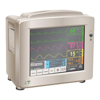
Introduction The SC750 is a compact multi-parameter patient monitor which provides the following monitoring capabilities: • ECG (3 or 5 lead) • Respiration • • Non Invasive Blood Pressure • Temperature A factory fit chart recorder can also be supplied. The monitor is of fully moulded construction in a tough flame retardant ABS material. - Page 8 ECG / RESP 1 x Surface 1 x Rectal 1 x Central Temperature Probes (optional) 1 x ECG / RESP Patient Cable 1 x SpO Interface Cable 1 x Adult Finger Sensor NIBP 1 x NIBP Hose 1 x NIBP Standard Adult Cuff...
-
Page 9: Front Panel Controls And Indicators
Recorder 1 x Chart Paper Front Panel Controls and Indicators Front panel indicators Fig. 1 Green “~ “ ON Indicates mains power connected. Amber “CHG” ON Indicates that the internal battery is charging. Amber above the “On” / Off” button indicates the unit is switched on. -
Page 10: Rear Panel Features
Rear Panel Features Use only with a 250V fuse Use only with a 250V fuse Employer uniquement avec Employer uniquement avec un fusible de 250V un fusible de 250V Use only 250V fuses Use only 250V fuses Fig. 2 Mains Input Socket I/O Sockets (from the top) : •... -
Page 11: Patient Inputs
Patient Inputs All patient inputs are fully isolated from electrical earth. ECG and respiration rates are obtained via conventional electrodes and either a 3 or 5 way patient cable. Temperature measurements are obtained via thermistor based temperature sensors. Non-invasive Blood Pressure readings are gained using a plethysmographic cuff technique with cuff inflation provided by an internal pump. - Page 12 Lead I Lead i (CASC) 1 /cm br/m ADULT AUTO 5 37.9 40.0 SOMEBODY 30.0 PATIENT REF 40.0 38.1 30.0 mmHg REC : OK (MANUAL) °C 18 : 05 11 Apr 2005 RECORD SETUP SUSPEND TRENDS SPOT GO/STOP Fig. 4 The readouts are displayed as follows: Lifesign Trace Description...
- Page 13 The alarms in Table 2 below can be adjusted from within the appropriate set-up screen. Individual alarms or all alarms may be muted for the preset suspend period. When all alarms are muted the ‘INFO’ box displays the message ‘SUSPEND’ and the remaining suspend time is indicated by a bar graph or ‘∞’...
-
Page 14: Touch Screen
Patient Information Patient information, Name, Bed and Ref. No., which is displayed in the ‘INFO’ box, can be changed from the patient set-up screen. ADULT SOMEBODY PATIENT REF REC : OK (MANUAL) All information, including alarm settings, are automatically retained when the monitor is switched off. -
Page 15: Preliminary Checks
However, accidental damage can occur in transit and storage. For this reason we recommend that a thorough visual inspection is made immediately the unit is received. Should any damage be evident or any parts missing, ensure that Huntleigh Healthcare Ltd is informed at once. Storage... -
Page 16: Specifications
Outputs 10/100 Ethernet socket (RJ45) for connection to Smartsigns Central View, Serial port (9 pin ‘D’) for software upgrade for connection to Huntleigh Healthcare BD4000, 6 way mini DIN for external keyboard and a VGA socket for a slave monitor. -
Page 17: Environmental
Environmental Operating Storage 10°C to 40°C Temperature range -10°C to 50°C 30% to 90% (non condensing) Relative Humidity 0% to 99% (non condensing) 860mb to 1060mb Pressure 860mb to 1060mb Monitoring Functions Heart Rate range 15 – 300 BPM Selectable leads I, II, or III with the standard 3 lead option. - Page 18 Respiration Method Impedance measurement via the ECG chest electrodes. Accuracy ±2% ±1 digit Sensitivity 1Ω/cm; 3Ω/cm selectable. Range 4 – 150 Resp/min. Trends 1, 8 or 24 hour trend of respiration rate Alarms Apnea, high and low rate. Non-Invasive Blood Pressure Range 30 to 280mmHg.
-
Page 19: Accessories
Accessories ECG / Respiration Item Part No. 3 Way Trunk ACC-VSM-01 3 Way Combined ECG / RESP Patient Cable ACC-VSM-05 3 Way Fly Leadset RED, GREEN, YELLOW (Zero) ACC-VSM-06 5 Way Trunk ACC-VSM-146 5 Way Combined ECG / RESP Patient Cable ACC-VSM-147 5 Way Fly Leadset ACC-VSM-148... -
Page 20: System Connectors
System Connectors The SC750 may be connected to the Smartsigns® Central View Central Station via the LAN socket situated on the rear panel. Contact Huntleigh Healthcare for details prior to attempting this connection. A set of normally open contacts across pins 2 & 6 on the keyboard socket can... -
Page 21: Equipment Markings
Equipment Markings The following symbols are used on the SC750, their definitions are described below: - Symbol Description Type CF and the input is protected against defibrillation damage. On / Off / Standby Protective earth (ground). Equipotentiality Alternating current Attention - consult accompanying documents Communication link Serial port Keyboard... -
Page 22: Operation
Operation General Connect the monitor to the local mains supply. The green AC power LED on the front panel will illuminate. Note: To isolate the SC750 from the mains or line supply, disconnect the power cable from the mains inlet at the rear of the unit. - Page 23 Lead I Lead i (CASC) 1 /cm br/m ADULT AUTO 5 40.0 37.9 SOMEBODY 30.0 PATIENT REF 40.0 38.1 30.0 mmHg REC : OK (MANUAL) °C 18 : 05 11 Apr 2005 RECORD SETUP SUSPEND TRENDS SPOT GO/STOP Fig. 6 Normal Display Displayed on the screen are up to 5 parameters.
-
Page 24: Setup
Fig. 9 INFO Box ADULT SOMEBODY Above the touch switches and to the left is the PATIENT REF INFO box (Fig.9) to display patient details and any warning/error messages. REC : OK (MANUAL) 5.1.3 SETUP Fig. 10 SETUP screen SETUP Touching the screen at this button produces the SYSTEM SETUP screen as shown by Fig.10. -
Page 25: Lang - Set Language
5.1.3.1.1 Lang – Set Language On the Lang button is displayed the current selected language. A different language will appear each time the Lang button is pressed and the on-screen text will change to the new language. 5.1.3.1.2 Set Time and Date Selecting TIME/DATE from the SYSTEM menu will show the TIME/DATE dialogue box (Fig.12). -
Page 26: Exiting The System Screen
This is a teaching and demonstration mode where artificial waveforms are displayed. This mode is password controlled to prevent accidental use. Contact your Technical Services Department for details of the Password. 5.1.3.1.8 Exiting the System Screen Press the √ symbol or wait for about 20 seconds after the last use box will confirm the ‘New Patient?’... -
Page 27: Recorder
5.1.3.3 RECORDER Fig. 15 RECORDER SETUP Screen If a recorder is fitted, pressing RECORDER RECORDER SETUP from the SYSTEM set-up dialogue box gives access to the RECORDER SETUP Wave 1 screen from which the readouts to be Wave 2 printed can be selected and ‘Alarm Mode’ RESP Wave 3 can be set. -
Page 28: Trends
5.1.3.6 TRENDS Fig. 18 TRENDS SETUP Dialogue Box Pressing the TRENDS button in the SETUP dialogue TRENDS SETUP box opens the TRENDS SETUP screen (Fig.18). In the TRENDS SETUP is a button for each trend line on the main trend waveform display. Trend buttons that have a ‘wave’... -
Page 29: Suspend
5.1.4 SUSPEND SUSPEND button at the bottom of the screen is used to suspend all alarm activity for the period set up in the SYSTEM SETUP . When active the word SUSPEND, in red, will appear in the INFO box with a bar graph indicating the proportion of the time that the alarms will remain inactive. -
Page 30: Trend Period Selection
When the trend mode is selected the SPOT button becomes the Trend Period selection control and the Freeze button is used to select between graphical and tabular display of trends. Trends on all monitor functions are recorded over pre-programmed periods of 1 hour, 8 hours and 24 hours. -
Page 31: Spot Mode
The first selection of trends after the monitor has been switched on will show the graphical display. It will take a few seconds to draw an already recorded trend on screen. If there is no recorded TRENDS data then the first points will take 1 minute to appear in ‘1 HOUR’... -
Page 32: Freeze Trace
5.1.7 Freeze Trace When the waveform display is active the button to the left of RECORD GO/STOP is the freeze trace button. Pressing this button will freeze the traces on the screen for closer inspection. When freeze trace is active the button is ‘in’. When the Freeze button is pressed again it will show as ‘out’... -
Page 33: Ecg Monitoring
ECG Monitoring To monitor the ECG of a patient apply the electrodes as shown below and plug the ECG cable into the SC750. The ECG traces/traces selected will be displayed on the first (and, if selected, second trace lines) on the screen. In the ECG box will be displayed the Heart Rate and QRS detection. -
Page 34: Ecg Setup
Clean the area with an alcohol pad to remove all abrading residues and oils (not necessary with preparation solutions). Dry the skin. Snap the ECG lead wire to the electrodes prior to placement on the patient’s chest. Ensure that all conductive parts of electrodes and associated connectors do not contact other conductive parts including earth. -
Page 35: Gain
5.2.2.2 Gain Allows display gain selection between x ½, x1, x2, and x4. A gain of x1 is equivalent to 1cm/mV. 5.2.2.3 Mode Allows the user to select between “MONITOR” and “DIAGNOSTIC” filtering. 5.2.2.4 Filter Switches the 50/60Hz notch filter ON or OFF. 5.2.2.5 QRS Beep Turns the QRS beep ON or OFF. -
Page 36: High And Low Alarm Settings And Suspend
5.2.2.8.1 High and Low Alarm Settings and Suspend At the top of the dialogue box are the current high and low settings with a + and – box top and bottom. The + and – buttons allow the user to adjust the alarm levels manually. -
Page 37: Spo2 Monitoring
SpO2 Monitoring SpO2 monitoring starts when the sensor is clipped to the patient and the patient cable is connected to the SC750. While monitoring the SpO2 waveform is displayed as the second parameter on screen with %O2 and the PR (pulse rate) displayed in the SpO2 box. A bar graph is also shown indicating signal strength. -
Page 38: Interference
If no satisfactory reading can be obtained the symbol appears with the words “LONG SEARCH”. If this occurs investigate to ensure that the circulation is not being impeded and that no foreign object, such as sticking plaster, is blocking the inside of the probe. If no obvious reason can be found try connecting a different probe. -
Page 39: Parameter
5.3.4.1 Parameter The Parameter button is used to turn the SpO2 function ON or OFF. If the function has been turned off and the Parameter button is pushed, to turn the function on, after a brief period, during which a consistent signal is being characterised, the trace will appear along with digital readouts of SpO2 and Pulse Rate (PR). -
Page 40: Use Defaults
5.3.4.3.3 Use Defaults The next button in the dialogue box is Use Defaults. To the right of the button is the high level alarm default value and to the left the low alarm default value. Pressing the Use Default button substitutes the high and low default values for the current alarm settings. -
Page 41: Respiration Monitoring
Respiration Monitoring Respiration is monitored from the ECG electrodes attached to the patient. While monitoring ECG the Respiration waveform is shown as the 3rd parameter on the screen. In the RESP box the breathing rate (BR) is displayed along with an indication of inhalation or exhalation. 5.4.1 Electrode Application for RESP Monitoring Respiration monitoring is achieved using the ECG patient cable. -
Page 42: Resp Setup
If reusable or non-gelled electrodes are used, apply gel to the electrodes. If pre-gelled disposable electrodes are used, peel the backing from the electrode adhesive and apply the electrodes. NOTE Do not apply excessive pressure to the centre of the electrode as it may force gel beneath the adhesive and cause the electrode to loosen. -
Page 43: Sens
5.4.2.2 Sens For respiration there are 2 sensitivities available either 1Ω/cm or to 3Ω/cm. Pressing the Sens button selects the sensitivity required and displays it on the button. 5.4.2.3 BR ALARM SETUP Pressing the ‘BR ALARM SETUP’ button will reveal the dialogue box shown below in Fig.30. -
Page 44: Tick √ Button
5.4.2.3.4 Tick √ Button Use the tick to exit the BR ALARM SETUP screen and return to the RESP SETUP dialogue or push the SETUP button to exit from setup completely. 5.4.2.4 Exiting Pushing the Tick button or the SETUP button will close the RESP SETUP dialogue and return to normal monitoring. -
Page 45: Temp Setup
5.5.1 TEMP SETUP With a probe inserted pressing the ‘TEMP’ or by pressing TEMP within the SETUP screen (Fig.10) will cause the TEMP SETUP (Fig.31) screen to be displayed. TEMP SETUP Lead I Lead i (CASC) T1 ALARM SETUP 1 /cm T2 ALARM SETUP br/m ADULT... -
Page 46: High And Low Alarm Settings And Suspend
5.5.1.1.1 High and Low Alarm Settings and Suspend At the top of the dialogue box are the current high and low settings with a + and – box top and bottom. The + and – buttons allow the user to adjust the alarm levels manually. -
Page 47: Non-Invasive Blood Pressure (Nibp) Monitoring
Non-invasive Blood Pressure (NIBP) Monitoring NIBP measurement uses the oscillometric method via a cuff, inflated and deflated through the SC750. It is capable of accurately sensing blood pressure on any portion of the arm or leg with sufficient blood flow. This includes the general regions of the upper arm, lower arm, thigh, calf, ankle, and arch of the foot. -
Page 48: Connecting The Cuff To The Sc750
5.6.1 Connecting the Cuff to the SC750 Push the cuff extension hose bayonet connector gently onto the NIBP spigot located on the right-hand side of the monitor and turn clockwise until locked. NB: do not force the connector to avoid breaking the locking lugs. Select the correct cuff for the patient and wrap around the patient’s limb. -
Page 49: Mode
5.6.2.1 Mode The Modes available are MANUAL, AUTOMATIC. TURBO and MANOMETER. If Calibration mode is disabled then MANOMETER is removed from the list of modes. MODE SETTING FREQUENCY OF RECORDING ‘AUTOMATIC’ Every 2, 3, 4, 5, 10, 15, 30, 60 or 90 minutes. ‘TURBO’... -
Page 50: Sys Alarm Setup
5.6.2.5 SYS ALARM SETUP Pressing this button produces the screen shown in Fig.35 enabling the systolic alarms to be turned on or off and their levels set. The Auto Limit button is used to set the alarm levels 20 above and 20 below the last recorded systolic reading. -
Page 51: Map Alarm Setup
5.6.2.7 MAP ALARM SETUP Pressing this button produces the MAP alarm setup dialogue box (Fig.37) enabling the MAP alarms to be turned on or off and their levels set. The Auto Limit button is used to set the alarm levels 20 above and 20 below the last recorded MAP reading. -
Page 52: Alarms
ERROR MESSAGE CAUSE AND REMEDY ‘EXCESSIVE Caused by patient movement judged to be sufficient MOTION’ to cause an un-reliable reading. ‘REPOSITION CUFF’ This is self evident ‘RANGE EXCEEDED’ Indicates that the applied air pressure has reached its safe maximum. Alarms 5.7.1 Altering &... -
Page 53: Factory Alarm Priority Settings
MEDIUM ALARM SETUP (SOUND 2) MEDIUM ECG ASYSTOLE HIGH (SOUND 1) (SOUND 1) MEDIUM Lead I ECG HR low (SOUND 1) HIGH (SOUND 2) MEDIUM ECG HR high (SOUND 1) HOLD ECG ALARMS Lead i (CASC) MEDIUM RESP APNOEA (SOUND 1) MEDIUM (SOUND 2) MEDIUM... -
Page 54: Alarm Ranges & Default Settings
5.7.6 Alarm Ranges & Default Settings All of the alarm limits are checked automatically and continuously. The alarms can be modified independently by selecting the appropriate parameter set up screen. All enabled alarms may be auto set. Alarms that have been silenced are supported by a graphical symbol and a screen message to inform the user. -
Page 55: The Printer/Recorder
The Printer/Recorder 5.8.1 Paper Loading. Open the door at the side of the unit by de-pressing the release mechanism. The door will swing down. Remove the spent paper core by pulling it towards you gently. Place a new paper roll between the two tabs of the paper holder. -
Page 56: Recording Procedure
5.8.2 Recording Procedure The recorder has two modes of operation: Record - activated by pressing the RECORD GO/STOP area at the bottom of the screen. In this mode the recorder runs in real time continuously. The trace on the recorder corresponding to the waveforms selected on the RECORD SETUP screen. -
Page 57: Trouble Shooting
Trouble Shooting This section gives some of the more common problems encountered during use together with their possible causes. If the operator cannot locate the problem after consulting the table in this section, the monitor should be switched off, disconnected from mains power source and a qualified technician should be consulted. -
Page 58: Maintenance
Maintenance Care of your Equipment Although the SC750 is robust and has been designed to withstand normal clinical use, the unit contains delicate components, such as the display and accessories, which should be handled and treated with care. It is recommended that the unit and accessories are tested on a regular basis. We recommend that the system is included into an annual calibration programme where the accuracy of the system is checked against the manufacturers’... - Page 59 SpO2 equipment cleaning.- Unplug the device before cleaning or disinfecting. Do not autoclave or ethylene oxide sterilise, or immerse in any liquid. Clean with soapy water and dry. Patient ECG leads. - After use the patient leads should be cleaned with warm water or a neutral cleaner and wiped dry.
-
Page 60: Further Maintenance
Butyl alcohol, Denatured ethanol, Freon™, Mild chlorine bleach solution, Isopropyl alcohol, Trichloroethane, Trichloroethylene, Acetone, Vesphene II, Enviroquat®, Staphene®, Misty®, Glutaraldehyde. Further Maintenance Huntleigh Healthcare recommends that preventative maintenance checks are carried out at least annually. Maintenance must only be carried out by suitably qualified personnel... -
Page 61: Warranty & Service
EEC as ammended by 2007/47/EC and have been subject to the conformity procedures laid down by the Council Directive. Manufactured in the UK by Huntleigh Healthcare Ltd. As part of the ongoing development programme the company reserves the right to modify specifications and materials without notice. - Page 62 310-312 Dallow Road, Luton, Beds, LU1 1TD © Huntleigh Healthcare Limited 2006, 2011 COMPANY, MEMBER OF THE GETINGE GROUP ® and ™ are trademarks of Huntleigh Technology Limited As our policy is one of continuous improvement, we reserve the right to 747313-6 modify designs without prior notice.
Need help?
Do you have a question about the Smartsigns Compact SC750 and is the answer not in the manual?
Questions and answers