Table of Contents
Advertisement
Quick Links
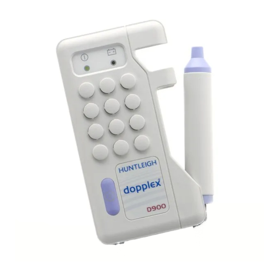
HIGH SENSITIVITY
POCKET DOPPLERS
SERVICE MANUAL
© Huntleigh Healthcare Limited 2004-2009
726374-3 3
Service Agreements
Periodic inspection is essential to ensure continued effective operation. Contact the Company
or its approved agents or distributors for further information on service contracts.
® and ™ are trademarks of Huntleigh Technology Limited
As our policy is one of continuous improvement, we reserve the right to modify designs without prior
notice.
R
...with people in mind
Advertisement
Table of Contents


Need help?
Do you have a question about the D900-P and is the answer not in the manual?
Questions and answers