Table of Contents
Advertisement
Advertisement
Table of Contents

Related Manuals for Huntleigh Smartsigns Compact SC1000


Summary of Contents for Huntleigh Smartsigns Compact SC1000
- Page 1 SC1000 Smartsigns ® Compact...
-
Page 2: Table Of Contents
1. Quality Reliability and Safety ......4 2. Preliminary Checks ........6 3. - Page 3 16. Non-Invasive Blood Pressure (NIBP) Monitoring ... . .42 16.1 Connecting the cuff to the SC1000 ....42 16.2 NIBP set up .
-
Page 4: Quality Reliability And Safety
All modifications and repairs to the equipment must carried out by qualified service engineers, agents or hospital technicians authorised by Huntleigh Healthcare. Cautions Note The following are descriptions of general hazards and unsafe practices that could result in death, severe injury or product damage. - Page 5 Possible Do not immerse any portion of the instrument in water. Equipment Fluid spills may damage the instruments electrical Damage components. Do not sterilise this product. Sterilisation environments can cause severe damage. Do not autoclave or gas sterilise accessories unless manufacturer instructions clearly approve it.
-
Page 6: Preliminary Checks
We recommend that a thorough visual inspection is made prior to installation. Should any damage be evident or any parts missing, ensure that Huntleigh Healthcare, Diagnostic Products Division are informed at once. Should the unit not be required for immediate use, it should be... -
Page 7: Introduction
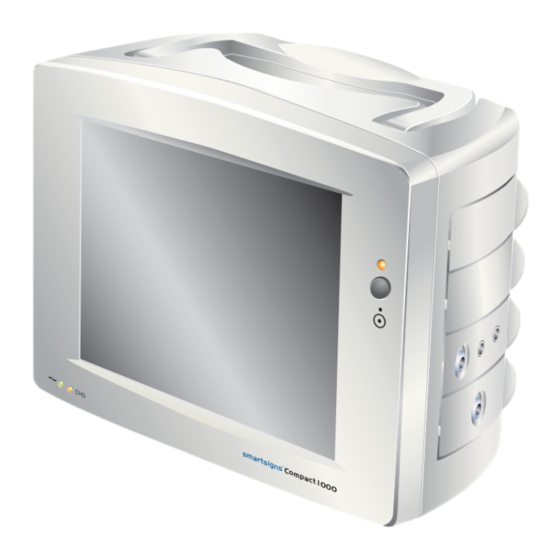
4. Introduction The Smartsigns® Compact series is a portable multi-parameter Vital Signs monitor capable of displaying the patient's vital signs on a 10.4" colour TFT screen. Interchangeable application modules can be fitted to the unit to suit the demands of the different clinical setting. a r t s i g C o m... - Page 8 A 50 mm wide high-speed thermal printer is available as a factory fit option. ECG and respiration are obtained via conventional electrode placement via a standard ECG patient cable. Temperature readings are obtained via a range of YSI 400 compatible temperature sensors. Non-invasive Blood Pressure measurements are made using the Oscillometric technique.
-
Page 9: Accessories
5. Accessories The system is supplied with the following standard accessories: - a r t s i g C o m p a c 1 x SC1000 t 1 0 1 x Power Cord 1 x Instructions For Use... - Page 10 Module 1- ECG, SpO , TEMP (2), RESP 5 Lead Cable 1 x Surface 1 x Rectal 1 x Central 3 Lead Cable Temperature Probes (optional) 1 x ECG / RESP Patient Cable 1 x Adult Finger Sensor 1 x SpO Interface Cable...
- Page 11 Module 2 - NIBP NIBP NIBP 1 x NIBP Hose 3 x NIBP Cuffs...
- Page 12 Module 3 - IBP 1 x Mounting Bracket (dual) 1 x Dual IBP Cable 2 x Pressure Transducers 1 x Stand Clamp 1 x Monitoring Set...
- Page 13 Paediatric or Infant / Neonate) Factory Fit Option Recorder 1 x Chart Paper A wide range of accessories is available for the Smartsigns® range and can be ordered from your supplier or by contacting Huntleigh Healthcare Diagnostic Products Division directly.
-
Page 14: Front Panel Controls And System Displays
Front Panel Controls and System Displays The system ON/OFF button is located on the right hand side of the unit. Pressing the button once switches the system ON. ON/OFF/STANDBY Interchangeable Application Modules a r t s i g C o m p a c t 1 0 NOTE... -
Page 15: Rear Panel
7. Rear Panel The following components are located on the rear / side of the unit :- Description 50mm High speed thermal printer (factory fit option) Mains input socket I/O sockets: - • Ethernet socket • Serial Port • Keyboard •... -
Page 16: Symbols
8. Symbols The following symbols are used on the SC1000, their definitions are described below: - Symbol Description Green LED indicating that mains power is connected. Yellow LED indicating that the internal battery is charging. Type CF with defibrillator protection On/Off/Standby Protective earth (ground) Equipotentiality... -
Page 17: Operation
9. Operation Connect the monitor to the local mains supply. FUSE TYPE IEC 127 2AH250V The green AC power LED on the front panel will illuminate. Use only 250V fuses Use only 250V fuses Note: To isolate the SC1000 from the mains or line supply, disconnect the power cable from the mains inlet at the rear of the unit. - Page 18 Application screen The screen is arranged into a series of waveforms and numerical indicators. Position 1 Position 2 Position 3 Position 4 Position 5 Position 6 Command Bar Command Bar At the bottom of the display area is a command bar, which provides the following facilities: - SET-UP TRENDS...
-
Page 19: Setting The Unit To Standby
Above the command bar is an area JONES 123456-A reserved for the patient's name, identification number and system messages. Patient information and system settings are saved in the systems memory when the unit is switched OFF. Enabling / Disabling the Touch Screen The touch screen may be locked / un-locked by pressing the padlock icon in the bottom right hand corner of the screen. -
Page 20: Set-Up
Set-up Press the 'Set-up' TAB to display the Set-up screen. SETUP Set-up screen. SYSTEM PATIENT RECORDER RESP TEMP IBP1 IBP2 NIBP DEFAULTS ALARM SETUP From this screen the operator can adjust the following parameters:- • System • Patient • Recorder (if fitted) •... -
Page 21: System Controls
System controls SYSTEM Press the TAB at the top of the SETUP set-up screen to enable the following SYSTEM options: - PATIENT • Language RECORDER RESP • Set Time and Date TEMP • Alarm suspend options IBP1 IBP2 • Display brilliance NIBP •... -
Page 22: Brilliance
9.4.4 Brilliance Press the + or - symbols to increase or decrease the screen brilliance. The current level is indicated by the graphical symbol. Press to exit from this function. 9.4.5 Volume Press the + or - symbols to increase or decrease the pulse tone level. -
Page 23: Patient
Patient SETUP PATIENT Pressing the TAB from the SYSTEM screen displays the patient PATIENT information screen. From this screen, RECORDER the operator can add the patient's RESP name and reference number to the system. TEMP IBP1 IBP2 NIBP DEFAULTS ALARM SETUP PATIENT NAME/REF Name... -
Page 24: Recorder
Recorder SETUP If a recorder option is fitted, pressing SYSTEM RECORDER provides access to the PATIENT format of the printout. RECORDER See section 19 for specific details. RESP TEMP IBP1 IBP2 NIBP DEFAULTS ALARM SETUP Defaults DEFAULTS Pressing allows the user to SETUP select the factory default alarm settings. -
Page 25: Trends
11. Trends Trends are displayed graphically or tabular over a 1, 8 or a 24-hour period. From the main application screen, pressing the displays the trends screen. The system displays three buttons. From this point, the operator can customise the data. Switches the trend scale between 1, 8 or 24 1 HOUR hours. -
Page 26: Ecg Monitoring
12. ECG Monitoring IMPORTANT Check all cables before operation. Only use the patient cable supplied with the system. DO NOT connect any NON-ISOLATED accessories to the system when connected to a patient. The system provides an isolated circuit for the ECG capability; ensure that the conductive parts of the ECG patient cable do not contact any other conducting parts including ground. -
Page 27: Adult Ecg Electrode Placement
12.2 Adult ECG Electrode placement There are several sites for positioning ECG electrodes; these are dependant on the patients' physiological characteristics and condition. In most cases, ECG signal deficiencies may be improved by repositioning one or more of the electrodes. The best monitoring results will be obtained by placing the electrodes on the chest. -
Page 28: Setting Up The Ecg Waveform
Do not allow the ECG cable to place stress on to the ECG electrodes, as this will produce poor quality recordings. NOTE - If reusable or non-gelled electrodes are used, apply gel to the centre of the electrodes. If pre-gelled disposable electrodes are used, peel the backing from the electrode adhesive and apply the electrodes according to the manufacturers instructions. - Page 29 Lead Lead Press the TAB to select the appropriate lead selection ( I, II, III, AVR, AVL, AVF & V). Use the touch screen to adjust the setting. Press to exit from this function. Gain Gain Press the TAB to display the gain selection (x ½, x1, x2, and x4). Use the touch screen to adjust the setting.
-
Page 30: The Ecg Waveform
Alarms Use the touch screen to adjust the setting. The alarm levels can be set for both high and low limits using the + or - symbols. Pressing the symbol turns the alarm OFF or ON. Alarm ON Alarm OFF Press to save and exit from function. -
Page 31: Respiration Monitoring
13. Respiration Monitoring IMPORTANT This system uses a transthoracic method to determine the respiration rate. Check all cables before operation. Only use the patient cable supplied with the system. Respiration monitoring is achieved using a special patient cable. This cable does not contain protective resistors found on the standard SC1000 ECG cable. -
Page 32: Respiration Electrode Placement
13.1 Respiration electrode placement Note that the electrode positioning may be optimised for either transthoracic or transabdominal respiratory monitoring. These positions will offer the maximum strength for combined respiration and ECG signals when both parameters are to be monitored. Proper electrode application is particularly critical when monitoring respiration. -
Page 33: Respiration Set Up
13.2 Respiration set up RESP RESP SETUP Press the area of the screen to display the The following options will be available: - RESP SETUP Parameter Sens High Auto Limit Parameter This switches the RESP monitoring function ON or OFF. Use the touch screen to adjust the setting. -
Page 34: The Respiration Waveform
Alarms Use the touch screen to adjust the setting. The alarm levels can be set for both high and low limits using the + or - symbols. Pressing the symbol turns the alarm OFF or ON. Alarm ON Alarm OFF Press to exit from function. -
Page 35: Spo Monitoring
14. SpO Monitoring IMPORTANT The SC1000 series uses an advanced digital pulse oximetry system supplied by BCI®. The BCI® oximetry sensors are indicated for use in continuous non- invasive monitoring of arterial oxygen saturation and pulse rate determination. Only use BCI® oximetry sensors with the SC1000 series of monitoring systems. -
Page 36: Patient Preparation / Connection
14.1 Patient preparation / connection For Use With Adults Insert the patient's digit to the sensor. The preferred digit is the index finger (adult). The digit is correctly inserted when the tip of the finger touches the rear of the guideposts. Ensure the sensor cable extends along the top of the patient's hand. - Page 37 For Use With Neonates Application of the Neonate Multi- Site Sensor. Secure sensor with wrap, tape, or bandage. Secure sensor cable to patient, to provide additional strain relief. Secure sensor with wrap, tape, or bandage. Secure sensor cable to patient, to provide additional strain relief.
-
Page 38: Spo
14.2 SpO set up Parameter Press the area of the screen and set "ON", this activates the trace. Press the area of the screen to display the SETUP options. From this point, the operator can select from the following: - Parameter Parameter Press the... -
Page 39: The Spo 2 Waveform
Alarms Use the touch screen to the adjust setting. The alarm levels can be set for both high / low heart rate limits and the % saturation level using the + or - symbols. Pressing the symbol turns the alarm OFF or ON. Alarm OFF Alarm ON Press... -
Page 40: Spo 2 Error Messages
14.4 SpO Error Messages The following section provides the user with a description of ERROR messages, which may be displayed during respiration measurement. Error Message Cause Rectification No sensor connected to Connect the sensor to 'NO SENSOR' system the system 'SENSOR OFF Sensor detached from Re-apply sensor to the... -
Page 41: Temperature Monitoring
15. Temperature Monitoring Temperature probes are not supplied with the system, however, the SC1000 supports YSI 400 compatible sensors. Follow the manufactures instruction for use. Insert the temperature probe(s) into the sockets labelled T1 and or T2 on the ECG / TEMPERATURE / SpO module. -
Page 42: Non-Invasive Blood Pressure (Nibp) Monitoring
16. Non-Invasive Blood Pressure (NIBP) Monitoring The system uses the Oscillometric method via a cuff which is inflated and deflated through the SC1000. 16.1 Connecting the cuff to the SC1000 Connect the hexagonal bayonet-fitting end of the cuff extension hose to the NIBP socket on the module, push the connector gently and turn clockwise until it locks. -
Page 43: Nibp Set Up
The following table can be used as a guide to help with site selection: - Patient group Measurement site Adult Upper arm Paediatric Upper arm Neonatal Upper arm or leg 16.2 NIBP set up NIBP NIBP SETUP Press the area of the screen to display the options. - Page 44 Patient Group ADULT PEADIATRIC NEONATE This switches between patient groups and sets the target pressure and inflation times. Use the touch screen to select the required option. Press to exit this function. Mode Manual Automatic Turbo Mode Press the TAB to select operation.
- Page 45 Start Pressure* Start Pressure Press the TAB to set the target cuff pressure. In adult and paediatric mode, the target pressure can be set to 80, 100, 120, 140, 160, 180, 200, 220 or 240 mmHg. In neonatal mode, the target pressure can be set to 60, 80, 100 or 120 mmHg. Press to exit this function.
-
Page 46: Making A Bp Measurement
16.3 Making a BP measurement NIBP Press the TAB at the bottom of the screen to initiate the GO/STOP measurement. The cuff will gradually inflate. After approximately 30 seconds the system will complete the measurement and display the readings in the NIBP area of the screen: - 120/80 (97) -
Page 47: Nibp Error Messages
16.4 NIBP error messages The following table gives some examples of error message and their rectification: - Error Message Cause Rectification 'LOOSE CUFF' Cuff incorrectly or loosely Reposition and tighten positioned. cuff. Press NIBP to restart. 'AIR LEAK' Cuff tubing loose at Disconnect and connectors. -
Page 48: Invasive Blood Pressure Monitoring
17. Invasive Blood Pressure Monitoring Invasive Blood Pressure measurements must only be carried out by, or under the supervision of qualified personnel. The catheters should not be used on limbs which are being used for other medical procedures. 17.1 Transducer set-up The following procedures must be strictly observed and carried out in the sequence indicated. -
Page 49: Priming The System
Connect the transducer cable to the transducer paying particular attention to the channel identification (I or II). Each of the free ends must be inserted into the appropriate blue socket/s on the IBP module labelled I and II. 17.2 Priming the system Follow the manufacturers priming instruction. -
Page 50: Zeroing The System
17.3 Zeroing the system Each channel can be set up / calibrated independently. Allow the transducer to warm up for 5 minutes before zeroing. Vent the transducer to atmospheric pressure by turning the ZERO stopcock off to the patient. Touch the appropriate IBP area of the screen to display the set-up screen and press ZERO to zero the transducer. -
Page 51: Ibp Set Up Options
17.5 IBP set up options Touch the appropriate IBP area of the screen to display the set up screen: - IBP1 SETUP Parameter ZERO - - - / - - - Layout - - - (- - -) - - - - - - High IBP2 SETUP... -
Page 52: The Invasive Pressure Waveform
Layout* Press the TAB to select the format of the IBP display: - Layout SYS / DIA SYS/DIA (MAP) (MAP) Press to exit from this function. Alarms Use the touch screen to the adjust setting. The alarm levels can be set for both high / low heart rate limits and the % saturation level using the + or - symbols. -
Page 53: Ibp Error Messages
17.7 IBP error messages The following table gives some examples of error message and their rectification: - Error Message Cause Rectification 'NOT ZEROED' System not zeroed Re-zero system... -
Page 54: Co Monitoring
18. CO Monitoring The SC1000 uses a sidestream technique to monitor CO Using the appropriate sampling line, the system can be used with intubated and non intubated patients. Typical connection to Non-Intubated Patient Sample Line For non-intubated patients apply the nasal cannula to the patient and connect the free... -
Page 55: Connecting The Sampling Line
Press the CO area on the screen to display the CO set up options. Ensure the parameter is set ON O, HELIUM SETUP COMPENSATION Parameter Amb. Pessure Balance Gas mmHg ZERO Anaesthetic COMPENSATION Mode high high etCO Auto Limit mmHg, kPa 18.1 Connecting the sampling line Insert the sampling line into the module, a 'click' will be heard... -
Page 56: Zeroing The System
18.3 Zeroing the system Connect the sampling line to the module. Wait for the sensor warm up message to clear from the monitor display (for best results, wait 5 minutes for the module / sensor to warm up before performing the zero function). Make sure the sampling line is exposed to room air;... -
Page 57: Airway Adaptor Kit - Directions For Use
These items are single patient use - DO NOT re-use! Insert the sampling line into the module as shown in 18.1 ZERO the system if prompted by the monitor. Apply the sampling line to the patient as shown. After a short period, the capnogram will be displayed on the monitor's screen. -
Page 58: Co 2 Alarm Settings
Out of Range out of range Check Airway adaptor Check and clean airway adaptor if necessary. Check Sampling Line Check that sampling line is not occluded or kinked. System Error Contact Huntleigh Healthcare Service Dept. Error XXX Contact Huntleigh Healthcare Service Dept. -
Page 59: Recorder
19. Recorder 19.1 Paper Loading 1. Open the door at the side of the unit by de-pressing the release mechanism. The door will swing down. 2. Remove the spent paper core by pulling it towards you gently. Place a new paper roll between the two tabs of the paper holder. -
Page 60: Setting Up The Recorder
19.2 Setting up the Recorder The recorder can display up to four waveforms on the chart strip. The system has two modes of operation: - The recorder will start automatically when ALARM an ECG related alarm occurs other than 'lead off'. MANUAL The recorder will print a chart strip when the TAB is pressed. -
Page 61: Alarms
20. Alarms 20.1 Altering and Viewing Alarms Alarms are provided for each monitoring function. Alarm levels can be adjusted by entering the appropriate parameter set-up screen. Alarms can be adjusted up or down within its maximum and minimum permissible values. Alternatively, when a stable waveform or reading has been established, the area of the set-up screen can be... -
Page 62: Alarm Activation
20.3 Alarm Activation The alarm will sound when the alarm limits have been exceeded, unless they have been muted or the alarm suspension is active. If an alarm has been disabled from the set-up screen, the alarm OFF symbol will be displayed continuously to the right of the display. If the area at the bottom of the screen is pressed, all alarms will be disabled and SUSPEND will be displayed in large letters in... -
Page 63: Alarm Ranges And Default Settings
20.4 Alarm Ranges and Default settings All of the alarm limits are checked automatically and continuously. The alarms can be modified independently by selecting the appropriate parameter set up screen. All enabled alarms may be auto set. Alarms that have been silenced are supported by a graphical symbol and a screen message to inform the user. - Page 64 Parameter Low Limit, Default High Limit, Default Resolution NIBP - Systolic Neonatal 40 to 115, 50 45 to 120, 100 1mmHg Paediatric 60 to 155, 75 65 to 160, 145 1mmHg Adult 60 to 245, 75 65 to 250, 220 1mmHg NIBP - Diastolic Neonatal...
- Page 65 Parameter Low Limit, Default High Limit, Default Resolution IBP 2 - Systolic Neonatal -9.9 to 94.9, 15 -4.9 to 99.9, 50 0.1mmHg Paediatric -9.9 to 94.9, 15 -4.9 to 99.9, 50 0.1mmHg Adult -9.9 to 94.9, 15 -4.9 to 99.9, 50 0.1mmHg IBP 2 - Diastolic Neonatal...
-
Page 66: Specifications
21. Specifications 21.1 Equipment classification Type of protection Class 1 and internally powered equipment against electric shock Degree of protection Type CF - equipment with an applied part, against electric intended for direct electrical connection to the shock heart. The equipment is defibrillation discharge protected. -
Page 67: General
21.2 General Supply Voltage 100-240V 50/60Hz. Fuse Type T2AH 250VAC (SCHURTER 0001-2707) Power Input 90 VA Screen 10.4 inch diagonal high brightness TFT flat panel display Trace Speed 50, 25, 12.5 and 6.25mm per second for ECG and SpO waveforms. The Respiration waveform trace speed is 6.25mm per second. -
Page 68: Environmental
21.3 Environmental Operating Storage 10°C - 40°C Temperature Range -10°C to +50°C 30% - 90% (non 0% - 99% (non Relative Humidity condensing) condensing) 860mb - 1060mb Pressure 860mb - 1060mb 21.4 ECG Heart rate range 15-300 BPM Selectable leads 3 lead:- I, II or III 5 lead:- I, II, III, V, AVR, AVF or AVL Selectable Gain... -
Page 69: Non-Invasive Blood Pressure
21.5 Non-invasive Blood Pressure Range 30 to 280mmHg. Cuff over pressure 300mmHg Accuracy ±5mmHg with a standard deviation no greater than ±8mmHg Display Systolic/diastolic and mean numerical display: graphical manometer display during cuff inflation/deflation also graphical bar display, with mean, on trend screen. Automatic ‘Turbo’... -
Page 70: Spo
21.7 SpO Range 0 - 99% Resolution Accuracy Adult 70 - 99% ±2% Less than 70% undefined Neonate 70 - 99% ±3% Less than 70% undefined Averaging 8 beat average Pulse Rate 30 - 254bpm, ±2bpm or ±2% Range Patient Input <... -
Page 71: Temperature (Dual Channel)
12.9 Temperature (Dual Channel) Method Thermistor (YSI 400 series compatible) Accuracy ±0.1°C ± 1 digit Range 20°C - 45.5°C Display T1 or T1+T2+ Trends 1, 8 or 24 hour trend of T1 and T2 Alarms High and Low temperature on T1 and T2. 12.10 Core technology Respironics LoFlo™... -
Page 72: Recorder
- cont. Calibration No routine user calibration required Compensation Expired O , Balance gas (N O, He) and anaesthetic agents Range: 0 to 100% Compensation Resolution: 1% Default: 16% Range: 0 (off) or 1 (on) Compensation Default setting: Off Note: If ON, the monitor assumes the balance of the mixture is O Range: 0 (off) or 1 (on) Compensation... -
Page 73: Accessories
22. Accessories ECG / RESP Item Part No. 5 Lead ECG / RESP Cable Set ACC-VSM-147 3 Lead ECG / RESP Cable Set ACC-VSM-05 5 Lead ECG Main Cable ACC-VSM-146 3 Lead ECG Main Cable ACC-VSM-68 5 Chest Lead Pack ACC-VSM-148 3 Chest Lead Pack ACC-VSM-06... - Page 74 NIBP Item Part No. Disposable Neonatal Cuff Size 1(Box of 10) ACC-VSM-129 Disposable Neonatal Cuff Size 2 (Box of 10) ACC-VSM-130 Disposable Neonatal Cuff Size 3 (Box of 10) ACC-VSM-131 Disposable Neonatal Cuff Size 4 (Box of 10) ACC-VSM-132 Disposable Neonatal Cuff Size 5 (Box of 10) ACC-VSM-133 Reusable Infant Cuff 8 - 13cm ACC-VSM-195...
- Page 75 (Side stream) Item Part No. Adult Nasal Cannula, (Box of 10) ACC-VSM-203 Paediatric Nasal Cannula, (Box of 10) ACC-VSM-204 Infant/Neonatal Nasal Cannula, (Box of 10) ACC-VSM-205 Straight Sampling Line, (Box of 10) ACC-VSM-206 Straight Sampling Line with Filter, (Box of 10) ACC-VSM-207 Adult/Paediatric Airway Adaptor Kit >4mm, ACC-VSM-208...
-
Page 76: Care Of Your Equipment
23. Care of your Equipment Although the SC1000 is robust and has been designed to withstand normal clinical use, the unit contains delicate components such as the display and the accessories, which should be handled and treated with care. It is recommended that the unit and accessories are tested on a regular basis. -
Page 77: Cleaning And Disinfecting
24. Cleaning and Disinfecting The system can be wiped with a soft disposable cloth dampened with a mild detergent and warm water solution. Avoid the electrical contacts and connectors. Do not allow any fluid to seep into the system, or the area around the display. - Page 78 equipment cleaning Unplug the device before cleaning or disinfecting. Do not autoclave or ethylene oxide sterilise, or immerse in any liquid. Clean with soapy water and dry. Patient ECG leads The patient leads should be cleaned with warm water or a neutral cleaner and wiped dry.
- Page 79 Cleaning the NiBP cuffs Gently wipe the cuff with a cloth dampened with a suitable cleaning solution. Thoroughly wipe off excess cleaning solutions. Do not allow water to enter into the cuff. Approved cleaning solutions include: - Common hospital disinfectants including, Clorox®, liquid bleach (1:10 solution of Clorox®...
-
Page 80: Fault Finding
25. Fault Finding The following table is intended to help the user if they encounter any problems:- Symptom Possible cause/remedy Power cable not connected to live power source Green power indicator not illuminated Defective power cable Mains input fuses blown Amber unit ‘ON’. -
Page 81: Maintenance
Mark the package 'Service Department ' For further details, refer to NHS document HSG(93)26 (UK only). Huntleigh Healthcare reserves the right to return product that does not contain a decontamination certificate. A service manual is available for the Smartsigns® series. It contains service information, parts lists and fault finding guidelines. - Page 83 Council Directive. Manufactured in the UK by Huntleigh Healthcare Ltd. As part of the ongoing development programme the company reserves the right to modify specifications and materials without notice. Smartsigns® and Huntleigh are registered trademarks of Huntleigh Technology Ltd.
- Page 84 © Huntleigh Healthcare Limited 2005, 2012 AN ARJOHUNTLEIGH COMPANY, MEMBER OF THE GETINGE GROUP ® and ™ are trademarks of Huntleigh Technology Limited As our policy is one of continuous improvement, we reserve the right to modify designs without prior notice.
Need help?
Do you have a question about the Smartsigns Compact SC1000 and is the answer not in the manual?
Questions and answers