
Related Manuals for CEL-MAR ADA-7010D


Summary of Contents for CEL-MAR ADA-7010D
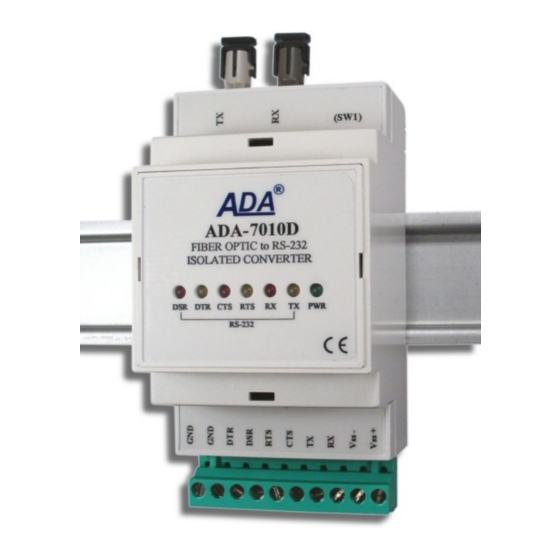
- Page 1 ADA-7010D User manual ADA-7010D Multimode Fibre-Optic to RS-232 Digital Converter Copyright © 2001-2017 CEL-MAR sp.j. io_ada-7010d_en_v3.20...
-
Page 2: Table Of Contents
ADA-7010D Contents 1. GENERAL INFORMATION..................................3 1.1. WARRANTED INFORMATION............................... 3 1.2. GENERAL CONDITIONS FOR SAFE USE............................ 3 1.3. CE LABEL....................................... 3 1.4. ENVIRONMENTAL PRESERVATION............................3 1.5. SERVICE AND MAINTENANCE..............................3 1.6. PACK CONTENTS..................................3 2. PRODUCT INFORMATION..................................3 2.1. PROPERTIES....................................3 2.2. -
Page 3: General Information
1.1. WARRANTED INFORMATION The ADA-7010D converter is covered by a two year warranty from date of sale. In case of being damaged it will be repair or the damaged component will be replace. The warranty does not cover damage caused from improper use, materials consumption or any unauthorized changes. -
Page 4: Description
2.2. DESCRIPTION Digital converter ADA-7010D is a device used to extend the RS232 ports of devices. Uses the signals: Tx, Rx, RTS, CTS, DTR, DSR of RS232 port. The converter receives data from the RS232 port and sends it via fiber optic to the second converter together with information about the state of RS232 line. -
Page 5: Isolation
Thus, the converter can support half duplex and full duplex transmission types. On the figure 3 is shown pictorially principle of operation of the converter and on figure 4 possibilities of use ADA-7010D like extender of RS232 PC port. -
Page 6: Installation
● not supply converter from power circuit device that generates large impulse interference such as transmitters, contactors, 4.1. ASSEMBLING ADA-7010D converter case is adapted to assembly on TS-35 (DIN35) rail. To install converter should mount device on the rail upper part of the case then press bottom part to hearing characteristic „Click” sound. -
Page 7: Power Supply Connection
4.4. POWER SUPPLY CONNECTION The power supply to ADA-7010D converter should be DC (regulated) from 10 V= to 30V=. Nominal power is typically 2W, e.g. ZS- 12/250 or DR-15-24. Power cable from DC power supplies to device must not be longer than 3m. -
Page 8: Configuration
Turn OFF and ON a power of the converter, the configuration will be set to factory default. 6.2. CONNECTION TO PC Connection of ADA-7010D to RS232 port, should be done by the use of DB9F-8WIRE cable (available in our offer). Way of connection is described in pt. 4.2. 6.3. CONFIGURATION BY USING ADACONFIG The configuration of ADA-7010D converter can be made by the use of ADAConfig Software - selling with converter. -
Page 9: Data Transmission Diagnostics
To check those counters press the button [Read transmission errors], and to delete (zeroing of counters in the memory of the converter) press [Delete transmission errors]. In case of parity errors or frame errors, should be checked the ADA-7010D converter's configuration and correctness connection of RS232 interface and to Fibre-Optic converter port. -
Page 10: Emergency Firmware Update
SW1-2 After micro-switch setting, ADA-7010D should be restarted, by turning OFF and then ON the power supply. The yellow LED will light continuously and the converter will be in Emergency Firmware Update mode. Now follow the description in point FIRMWARE UPDATE. -
Page 11: Rs232 Interface - Pin Description
Description ADA-7010D (TD) Data transmission from ADA-7010D Transmitter (RD) Data receiving via ADA-7010D Receiver (RTS) Request to Send Data from ADA-7010D Transmitter (CTS) Clear to Send Data to ADA-7010D Receiver (DSR) Data Set Ready to ADA-7010D Transmitter (DTR) Data device Ready to ADA-7010D... - Page 12 Thank you for purchasing CEL-MAR Company products. We hope that this user manual helped connect and start up ADA-7010D converter. We also wish to inform you that we are a manufacturer of the widest selections of data communications products in the world such as: data transmission converters with interface RS232, RS485, RS422, USB, Current Loop, Fibre-Optic Converters and Ethernet or Wi-Fi.
Need help?
Do you have a question about the ADA-7010D and is the answer not in the manual?
Questions and answers