Table of Contents

Related Manuals for Resol EM Extension module


Summary of Contents for Resol EM Extension module
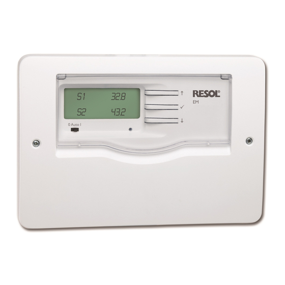
- Page 1 EM Extension module Mounting Connection Operation Thank you for buying this RESOL product. Manual Please read this manual carefully to get the best performance from this unit. Please keep this manual carefully. www.resol.com...
-
Page 2: Table Of Contents
Menu system ..........7 Only qualified electricians should carry out electrical is available upon request, please contact 5.1 Channel overview ..........7 works. RESOL. 5.2 Display channels ............8 5.3 Adjustment channels ..........8 Description of symbols Note Troubleshooting ........9 Strong electromagnetic fields can impair the Accessories .......... -
Page 3: Overview
Power supply: 100 ... 240 V~ (50 ... 60 Hz) Supply connection: type Y attachment Power consumption: < 1 W (standby) Mode of operation: type 1.B.C.Y action Rated impulse voltage: 2.5 kV Data interface: RESOL VBus ® Housing: plastic, PC-ABS and PMMA Mounting: wall mounting... -
Page 4: Data 2.1 Mounting
Installation upper fastening WARNING! Electric shock! crosshead Upon opening the housing, live parts screw are exposed! Î Always disconnect the device from power supply before opening the housing! Mounting The device must only be located in dry interior rooms. It is not suitable for installation in hazardous locations and should be protected against electromag- netic fields. -
Page 5: Electrical Connection
Semiconductor relays: Data communication / Bus ATTENTION! ESD damage! Electrostatic discharge can lead to The device is equipped with a RESOL VBus neutral conductor R4 ® damage to electronic components! data communication with the controller. Carry out normally open contact R4 Î... -
Page 6: Buttons
Flashing codes and warning symbols Selecting channels and adjusting values Operation 3.4.1 LED flashing codes Î Select the requested channel using buttons 1 and Buttons green: everything OK The device is operated via the 3 buttons next to the Î Briefly press button 3, SEt flashes (adjustment green flashing: manual mode display which have the following functions: mode) -
Page 7: Channel Overview
Initial commissioning Menu system For initial commissioning of the EM, proceed as follows: Channel overview 1. Connect the VBus ® cable Channel Description Page 2. Establish mains connection Value at sensor 1 3. Adjust the sub-address (SA) 4. Register the module in the controller (see con- Value at sensor 2 troller manual) Value at sensor 3... -
Page 8: Display Channels
Display channels Display of the software version Selecting the sensor type Error code display T1 … T6 This channel indicates the version number of the Adjustment range: 0 … 4 Error code firmware. Factory setting: 0 Display range: 0, 2 In this menu, a sensor type can be selected for each 0 = OK Display of the version number... -
Page 9: Troubleshooting
Troubleshooting If a malfunction occurs, the display symbols will indi- In the senor temperature display channels, line breaks Operating control lamp is permanently off. cate an error code (see chap. 3.4.2). or short circuits of the sensor cable will be displayed. Error messages for sensor faults are only indicated in the controller connected. -
Page 10: Sensors
Overvoltage protection device In order to avoid overvoltage damage at collector sensors (e.g. caused by local lightning storms), we recommend installting the overvoltage protection RESOL SP10. RESOL SP10 Article no.: 180 110 70... - Page 11 Notes...
- Page 12 This mounting- and operation manual including all parts is copyrighted. Another The texts and drawings in this manual are correct to the best of our knowledge. As use outside the copyright requires the approval of RESOL – Elektronische Re- faults can never be excluded, please note: gelungen GmbH.
Need help?
Do you have a question about the EM Extension module and is the answer not in the manual?
Questions and answers