Resol DeltaSol ES Manual
Hide thumbs
Also See for DeltaSol ES:
- Manual (28 pages) ,
- Manual for the specialised craftsman (32 pages) ,
- Manual (40 pages)

Related Manuals for Resol DeltaSol ES


Summary of Contents for Resol DeltaSol ES
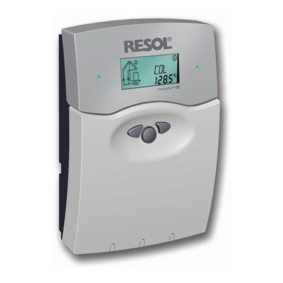
- Page 1 ® RESOL DeltaSol Mounting Connection Handling Fault localization Examples manual Thanks for buying a RESOL product. www.resol.de Read this manual carefully to get the best performance from this unit.
-
Page 2: Table Of Contents
(see page 3). We, RESOL Elektronische Regelungen GmbH, D-45527 Instructions Hattingen, declare under our sole responsibility that our product DeltaSol ES complies with the following stan- Attention should be paid dards: - to the statutory provisions for prevention of industrial... -
Page 3: Technical Data And Function Survey
1 x accessory bag can be selected via the menu and service, the controller is equipped 2 x screws and dowels represented graphically via the system- with RESOL VBus ® which opens the 4 x strain-relief and screws monitoring display. An integrated heat... -
Page 4: Installation
DeltaSol ® Installation Warning! Switch-off power supply before 1.1 Mounting opening the housing. Push Push - locking device push for opening push for closing The unit has to be located internally. It is not suitable for installation in hazardous locations and should not be sited near to any electromagnetic fields. -
Page 5: Actuators
Connection is effected without any polarity to both terminals marked „VBus“. One or more RESOL VBus modules can be connected by this data-bus, e. g.: • RESOL WMZ-M1, calorimeter module •... -
Page 6: Sensors
• The temperature sensors are connected to the termi- nals S1 ... S8 and GND regardless of the polarity. • A flowmeter RESOL V40 can be connected to the ter- minals V40 and GND regardless of the polarity. • The irradiation sensor (CS10) is to be connected to the terminals CS10 and GND with respect to polarity. -
Page 7: Operation And Function
DeltaSol ® Operation and function 2.1 Pushbuttons for adjustment The controller is operated by 3 pushbuttons below the display. The forward-key (1) is used for scrolling forward Operating control through the indication menu or to increase the adjustment lamp values. The backwards-key (2) is accordingly used for the backwards reverse function. -
Page 8: System Screen
DeltaSol ® 2.2.3 System-Screen The system screen (active system scheme) shows the schemes selected on the controller. It consists of several system component symbols, which are - depending on the current status of the system - either flashing, permanently shown or hidden. only system screen sensors sensor store up... -
Page 9: Commissioning
DeltaSol ® 3. Commissioning 1. Ac power supply must be activated. The controller pas- ses an initialisation phase in which the operating control On commissioning you have to adjust lamp flashes red and green. After having finished the initi- primarily the system scheme! alisation, the controller is in automatic operation (factory settings). -
Page 10: Control Parameter And Indication Channels
DeltaSol ® Controller parameter and adjustment channels 4.1 Channel overview Legend: Corresponding channel is only available if the option heat Corresponding channel is available. quantity measurement is activated (OHQM). MEDT Corresponding channel is available if the appropriate option The channel antifreeze function (MED%) is only shown if is activated. - Page 11 DeltaSol ® Chan- Description Option Collector cooling collector 1 OCX1 Option Collector cooling collector 1 Maximum collector temperature 1 CMX1 Maximum collector temperature 1 Option min. limitation collector 1 OCN1 Option min. limitation collector 1 Minimum temperature collector 1 CMN1 Minimum temperature collector 1 Option antifreeze collector 1 OCF1...
- Page 12 DeltaSol ® Channel survey: Systems Arr 11 ... 20 Chan- Description Collector temperature 1 COL 1 Collector temperature 1 TSTL Store temperature lower TST1 Store temperature 1 lower TSTU Store temperature 1 at the top Store temperature at the middle TST2 Store temperature 2 lower TFSB...
- Page 13 DeltaSol ® Chan- Description Option Collector cooling collector 1 OCX1 Option Collector cooling collector 1 Maximum collector temperature 1 CMX1 Maximum collector temperature 1 Option min. limitation collector 1 OCN1 Option min. limitation collector 1 Minimum temperature collector 1 CMN1 Minimum temperature collector 1 Option antifreeze collector 1 OCF1...
- Page 14 DeltaSol ® Channel survey: Systems Arr 21 ... 30 Chan- Description Collector temperature 1 COL 1 Collector temperature 1 TSTL Store temperature lower TST1 Store temperature 1 lower TSTU Store temperature 1 at the top Store temperature at the middle TST2 Store temperature 2 lower TFSB...
- Page 15 DeltaSol ® Chan- Description Option Collector cooling collector 1 OCX1 Option Collector cooling collector 1 Maximum collector temperature 1 CMX1 Maximum collector temperature 1 Option min. limitation collector 1 OCN1 Option min. limitation collector 1 Minimum temperature collector 1 CMN1 Minimum temperature collector 1 Option antifreeze collector 1 OCF1...
- Page 16 DeltaSol ® Channel survey: Systems Arr 30 ... 36 Chan- Description Collector temperature 1 COL 1 Collector temperature 1 TSTL Store temperature lower TST1 Store temperature 1 lower TSTU Store temperature 1 at the top Store temperature at the middle TST2 Store temperature 2 lower TFSB...
- Page 17 DeltaSol ® Chan- Description Option Collector cooling collector 1 OCX1 Option Collector cooling collector 1 Maximum collector temperature 1 CMX1 Maximum collector temperature 1 Option min. limitation collector 1 OCN1 Option min. limitation collector 1 Minimum temperature collector 1 CMN1 Minimum temperature collector 1 Option antifreeze collector 1 OCF1...
-
Page 18: Indication Channels
DeltaSol ® 4.2 Indication channels Please note: The indication channels are system dependant. Only the values necessary for the adjusted systems Arr 1 ... 36 (see channel overview pages 10 ff) are shown. 4.2.1 Indication of collector temperatures Shows current collector temperature. COL, COL1, COL2: collector temperature COL:... -
Page 19: Adjustment Channels
DeltaSol ® 4.2.7 Volume flow FLOW: Volume flow The volume flow of the solar system measured by the V40 Adjustment range to determine the transported heat amount. 0,00 ... 99,99 m³/h 4.3 Adjustment channels Please note: The adjustment channels are system dependent as well as the indication channels. Only that values necessary for the adjusted systems Arr 1 ... - Page 20 DeltaSol ® 4.3.2 ∆T -regulation DT O / DT1O / DT2O / DT3O: Primarily the controller works in the same way like a Switch-on temp. diff. adjustment standard differential controller. If the switch-on diffe- range 1,0 ... 20,0 K rence (DT O / DT1O / DT2O / DT3O) is reached, Factory setting 6.0 the pump is activated and after having got an impulse...
- Page 21 DeltaSol ® 4.3.5 Collector-limit temperature If the adjusted collector limit temperature (EM / EM1 / collector emergency shutdown EM2) is exceeded the solar pump (R1 / R2) is deactivated in order to avoid a damaging overheating of the solar com- ponents (collector emergency shutdown).
- Page 22 DeltaSol ® 4.3.9 Oscillating charge Respective adjustment values: Factory setting Adjustment range Priority [PRIO] 1 (2 / Layer store) oscillating break-time [tSP] 2 min. 1-30 min. oscillating charge time [tRUn] 15 min. 1-30 min. ES priority logic: The above-mentioned options and parameters are only DeltaSol ®...
- Page 23 DeltaSol ® 4.3.12 Thermostat function The thermostat function works independently from the after-heating Use of surplus energy solar operation and can e.g. be used for use of surplus energy or an after-heating. • AH O < AH F thermostat function is used for after-heating •...
-
Page 24: Tips For Fault Localization
DeltaSol ® 5. Tips for fault localization If a malfunction occurs, a notification is given on the display of the controller : warning symbol can fuse T4A spare fuse T4A operating control lamp Operating control lamp flashes red. On the display appears Operating control lamp permanently expires. -
Page 25: Miscellaneous
DeltaSol ® 5.1 Miscellaneous: Pump is overheated, but no heat transfer from collector to Pump starts for a short moment, switches-on/off the store, feed flow and return flow are the same warm; reapeatedly perhaps also bubble in the lines. Air in the system? Is the temperature diffe- Exhaust the system;... - Page 26 DeltaSol ® Stores are cooling during the night Control the return flow Further pumps, which are preventer in warm water connected to the solar circulation - o.k. store must also be che- cked. Collector circuit pump runs during the night ? Check controller Clearing or replacement.
-
Page 27: Accessory
If you are interested in realising a heat quantity balancing, a V40 is needed for measurement of the volume flow in the system. RESOL Service Center Software The RSC light software enables a readout of the measured values of the controller for visualisation and control of the system. - Page 28 Your own calcu- This especially applies for copies, translations, micro films lations and plans, under consideration of the current stan- and the storage into electronic systems. Editor: RESOL - dards and DIN-directions should only be basis for your Elektronische Regelungen GmbH projects.
Need help?
Do you have a question about the DeltaSol ES and is the answer not in the manual?
Questions and answers