Resol DeltaTherm E Installation, Operation, Functions And Options, Troubleshooting
Hide thumbs
Also See for DeltaTherm E:
Table of Contents
Advertisement
Quick Links
E
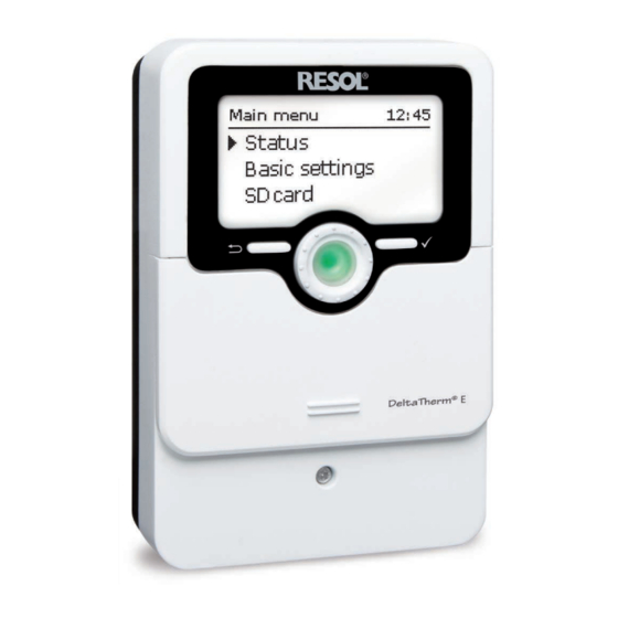
DeltaTherm
®
Beginning with firmware version 2.01
Control unit
Manual for the
specialised craftsman
Installation
Operation
Functions and options
Troubleshooting
en
Thank you for buying this RESOL product.
Manual
Please read this manual carefully to get the best performance from this unit. Please keep this manual safe.
www.resol.com
Advertisement
Table of Contents

Related Manuals for Resol DeltaTherm E


Summary of Contents for Resol DeltaTherm E
- Page 1 Control unit Manual for the specialised craftsman Installation Operation Functions and options Troubleshooting Thank you for buying this RESOL product. Manual Please read this manual carefully to get the best performance from this unit. Please keep this manual safe. www.resol.com...
- Page 2 Safety advice Target group Please pay attention to the following safety advice in order to avoid danger and These instructions are exclusively addressed to authorised skilled personnel. damage to people and property. Only qualified electricians are allowed to carry out electrical works. Danger of electric shock: Initial commissioning must be effected by authorised skilled personnel.
-
Page 3: Table Of Contents
Overview The DeltaTherm E is integrated in the FlowSol E and is designed for using • Increase in self-consumption of the PV system ® ® excess PV current for heating a store. An electric heater with 3 power stages (elec- •... -
Page 4: Technical Data
Technical data Power supply: 100 – 240 V~ (50 – 60 Hz) Supply connection: type Y attachment Controller Standby: < 1 W Inputs: 4 Pt1000 temperature sensors, 2 digital switching inputs Rated impulse voltage: 1.0 kV Outputs: 3 semiconductor relays, 1 potential-free extra-low voltage relay, 1 PWM Data interface: VBus ®... -
Page 5: System Overview
System overview Sensors Relay Flow temperature 1 / GND Loading pump R1 / N / PE Energy Controller meter Return temperature 2 / GND External backup R2 / N / PE heating external load 2 Store temperature 3 / GND (optional) Power unit (optional) -
Page 6: Installation
Installation Electrical connection Mounting WARNING! Electric shock! Upon opening the housing, live parts are exposed! WARNING! Electric shock! Î Always disconnect the device from power supply Upon opening the housing, live parts are exposed! before opening the housing! Î Always disconnect the device from power supply before opening the housing! ATTENTION! ESD damage! - Page 7 Sensor module VBus ® cable to the DeltaTherm ® Data communication VBus ® The connection is to be carried out at the terminals marked VBus (either polarity). The bus cable can be extended with a two-wire cable (bell wire). The cable carries low voltage and must not run together in a cable conduit with cables carrying a S0-1 S0-2...
- Page 8 Three-phase connection Single-phase connection Î Connect the current sensors and the conductors of the sensor module in Î Connect the current sensor and the conductor L1 of the sensor module di- phase directly at the energy meter. The arrow indicated on the current sensors rectly at the energy meter.
- Page 9 Controller 100 – 240 V 50 – 60 Hz 100 – 240 V 50 – 60 Hz DE-45527 Hattingen DeltaTherm ® E controller DE-45527 Hattingen IP 20 Made in Germany DeltaTherm E controller ® IP 20 Made in Germany R4|1 (1) A 30V Sensors R1-R3|1 (1) A 240 V~ R4|1 (1) A 30V...
- Page 10 Power unit Power supply of the controller: Mains connection of the electric heater: Regler Neutral conductor Neutral conductor Controller Conductor Conductor 0-10V T16A 250V~ Netz Protective earth conductor ⏚ Protective earth conductor ⏚ Mains VBus VBus Out1_N 1400 W Connection of the electric heater: Internal supply / data communication: Out2_N 800 W...
-
Page 11: Microsd Slot Of The Controller
MicroSD slot of the controller Operation and function of the controller The controller is equipped with a MicroSD card slot. Buttons and adjustment dial With a MicroSD card, the following functions can be carried out: • Store measurement and balance values onto the MicroSD card. After the trans- fer to a computer, the values can be opened and visualised, e.g. - Page 12 4.1.2 Selecting menu points and adjusting values During normal operation of the controller, the display shows the status menu. If no button is pressed for 1 min, the display illumination switches off. After 3 more minutes, the controller switches to the status menu. In order to get from the status menu into the main menu, press the left button (⟲)! Press any key to reactivate the display illumination.
- Page 13 Adjusting the timer When the Timer option is activated, a timer is in- dicated in which time frames for the function can be adjusted. In the Day selection channel, the days of the week are available individually and as frequently selected combinations.
- Page 14 Copying a time frame: Changing a time frame: In order to copy time frames already adjusted into an- In order to change a time frame, proceed as follows: other day / another combination, proceed as follows: Î Choose the day / the combination into which the time frames are to be copied and select Copy from.
-
Page 15: Menu Structure
Resetting the timer: Menu structure In order to reset time frames adjusted for a certain day Main menu or combination, proceed as follows Status Controller Controller Target temperature Measuring unit Minimum temperature Î Select the desired day or combination. Optional functions Hysteresis Basic settings ∆Ton... -
Page 16: Commissioning
Commissioning When the hydraulic system is fi lled and ready for operation, connect the power 1. Language: unit to the mains. Î Adjust the desired menu language. The controller has to be connected to the power unit (pre-connected) and to the sensor module by means of the VBus ®... -
Page 17: Main Menu
Main menu 7. Flush? Î Activate the fl ushing option, if necessary. The fl ushing option is used for venting the heating el- In this menu, different menu areas can be selected. ement. The following menus are available: If the fl ushing option is activated, the loading pump •... -
Page 18: Status
Status 4.5.2 Measured / Balance values In the Status / Meas./Balance v. menu, all current measurement values as well as In the status menu of the controller, controller status messages as well as measure- a range of balance values are displayed. ment / balance values and messages can be found. -
Page 19: Messages
4.5.3 Messages Controller In this menu, all adjustments for the hydraulic part of the FlowSol E can be made. ® In the Status / Messages menu, error and warning messages are indicated. The target temperature and the maximum return temperature have already been During normal operation, the message Everything OK is indicated. -
Page 20: Measuring Unit
The controller changes to the Max. temp. status (maximum shutdown). The maximum shutdown is used for shutting down the PV heating in order to prevent overheating of the store. If the temperature at the return sensor reaches the adjusted return maximum tem- perature, loading is blocked for 15 min. - Page 21 Optional functions In order to save a function, select Save function and confi rm the security enquiry by selecting Yes. In functions already saved, the menu item Delete function will appear instead. In order to delete a function already saved, select Delete function and confi rm the security enquiry by selecting Yes.
- Page 22 Internal backup heating External backup heating Opt. functions / Add new function / Backup heat.int. Opt. functions / Add new function / Backup heat.ext. Adjustment channel Description Adjustment range / selection Factory setting Adjustment channel Description Adjustment range / selection Factory setting Switch-on temperature 20 …...
- Page 23 S0 Excess S0 Heating Opt. functions / Add new function / S0 Excess Opt. functions / Add new function / S0 Heating Adjustment channel Description Adjustment range / selection Factory setting Adjustment channel Description Adjustment range / selection Factory setting Duration Impulse duration 30 …...
- Page 24 Smart Remote Inverter This function is used for operating the inverter at reduced power, if the excess exceeds a threshold. The operation is specifi ed by a switching signal. Opt. functions / Add new function / Inverter Adjustment channel Description Adjustment range / selection Factory setting Nominal power of the Power...
- Page 25 External load External load 2 This function is used for switching an additional external load (e.g. immersion heat- If the external load function has been activated, it is offered a second time (Load ext. er, heat pump), if enough power for its operation is available. 2).
-
Page 26: Basic Settings
4.10 MicroSD card Basic settings In the Basic settings menu, all basic parameters for the controller can be adjusted. Adjustment channel Description Adjustment range / selection Factory setting Normally, these settings have been made during commissioning. They can be subse- Rem. -
Page 27: Manual Mode
Note: 4.11 Manual mode The controller will only recognise a fi rmware update fi le if it is stored in a folder named ETHERM on the fi rst level of the MicroSD card. ÎCreate a folder named ETHERM on the SD card and extract the downloaded ZIP fi le into this folder. -
Page 28: User Code
4.12 User code ATTENTION! Damage through overheating! The access to some adjustment values can be restricted via a user code (customer). The manual mode > 0 % of the power stages in a system electri- 1. Installer 0262 (Factory setting) cally connected, but not hydraulically fi lled can lead to damage All menus and adjustment values are shown and all values can be altered. -
Page 29: Troubleshooting
Wago 2091-1130 Wago 2091-1130 Troubleshooting If a malfunction occurs, a message will appear on the display of the controller. WARNING! Electric shock! Upon opening the housing, live parts are exposed! Î Always disconnect the device from power supply be- Fuse fore opening the housing! The controller is protected by a fuse. - Page 30 The display is permanently off. The Lightwheel flashes red / green. ® Press the right button Is the message !VBus Sensor unit indicated in the Status / Messages menu? (✓) Display illuminated? Controller has been in Check the power supply of the controller. Is it The error LED of the sensor module is flashing red? disconnected? standby, everything OK...
-
Page 31: Index
Index Measured values ........................18 Messages ..........................19 Adjusting the timer ......................13 MicroSD card ........................ 11, 26 Mounting ..........................6 Balance values ........................18 Basic settings ........................26 Operating mode, relays ...................... 28 Clean it ..........................17 Power unit ..........................10 Commissioning menu ...................... - Page 32 This mounting- and operation manual including all parts is copyrighted. Another use faults can never be excluded, please note: outside the copyright requires the approval of RESOL – Elektronische Regelun- Your own calculations and plans, under consideration of the current standards and gen GmbH.
Need help?
Do you have a question about the DeltaTherm E and is the answer not in the manual?
Questions and answers